
Transmissive 2-bit anisotropic coding metasurface
2022-09-24 08:03PengtaoLai来鹏涛ZenglinLi李增霖WeiWang王炜JiaQu曲嘉LiangweiWu吴良威TingtingLv吕婷婷BoLv吕博ZhengZhu朱正YuxiangLi李玉祥ChunyingGuan关春颖HuifengMa马慧锋andJinhuiShi史金辉
Chinese Physics B 2022年9期
Pengtao Lai(来鹏涛) Zenglin Li(李增霖) Wei Wang(王炜) Jia Qu(曲嘉) Liangwei Wu(吴良威)Tingting Lv(吕婷婷) Bo Lv(吕博) Zheng Zhu(朱正) Yuxiang Li(李玉祥)Chunying Guan(关春颖) Huifeng Ma(马慧锋) and Jinhui Shi(史金辉)
1Key Laboratory of In-Fiber Integrated Optics of Ministry of Education,College of Science,Harbin Engineering University,Harbin 150001,China
2College of Aerospace and Civil Engineering,Harbin Engineering University,Harbin 150001,China
3State Key Laboratory of Millimeter Waves,School of Information Science and Engineering,Southeast University,Nanjing 210096,China
4School of Electronic Science,Northeast Petroleum University,Daqing 163318,China
5Synergetic Innovation Center of Wireless Communication Technology,Southeast University,Nanjing 210096,China
Keywords: transmissive coding metasurfaces,polarization control,orbital angular momentum
1. Introduction
Compared with traditional bulk optical elements, metasurfaces have many advantages such as ultrathin thicknesses,easy fabrications, flexible designs and planar geometries,which provide a promising approach to achieve flat optical components.[1,2]Metasurfaces unlock a myriad of novel applications, such as flat lens,[3-5]beam controllers,[6,7]and holograms.[8-10]Polarization is an important characteristic of electromagnetic (EM) wave. Different from isotropic metasurface, anisotropic metasurface can manipulate two orthogonal polarized waves independently and can be applied in polarization encrypt,[11-13]polarization imaging,[14,15]beam shaping,[16-18]and optical communications.[19]Combining the propagation and geometric phases, anisotropic metasurface can achieve independent phase profiles of arbitrary orthogonal states of polarization, thus makes anisotropic metasurface with versatile applications in multifunctional flat device.[20,21]
Coding and digital metasurfaces were proposed and demonstrated in 2014[22,23]and have experienced a rapid development in recent years. Coding metasurfaces have been studied from microwave,[24-29]terahertz electromagnetics[30-34]to acoustics.[35,36]Coding metasurfaces offer a powerful platform for manipulating EM waves in both the space and frequency domains by controlling different digital coding sequences.[25,33,37-39]Coding metasurfaces bridge the gap between the digital world and physical world. With the help of spatial and temporal modulation,non-linear harmonic manipulation and high-order orbital angular momentum (OAM) beam,[40-45]coding metasurfaces exhibit great potentials in wireless communication systems.EM waves carrying OAM have attracted tremendous attention since OAM was discovered in 1992,[46]where their phase profiles can be described using the term ejlφ(lis the topological charge andφis the azimuthal angle). The OAM beams can be generated by spiral phase plate,[47-49]diffraction grating,[50,51]spiral and twisted reflectors,[52,53]circular phase arrays,[54,55]and metasurface.[56-61]Intrinsically, the OAM beams with different topological charges are orthogonal, thus they can increase the capacity of communication system. As a result,OAM-based information transmission is important in coding metasurface-based communication system.[44]Most of the OAM beam generators based on coding metasurfaces operate in the reflection mode.[27,44,51,61]However, transmissive coding metasurfaces are highly desirable to manipulate the polarization state of wave and generate OAM beam, for instance fiber communication systems,[62-64]thus it is necessary to investigate an anisotropic coding metasurface operating in the transmission mode.
In this work, an anisotropic coding metasurface is proposed to independently manipulate electromagnetic responses ofxandypolarizations. The proposed metasurface is composed of cascaded cross-shaped structures to achieve high transmission and full phase coverage in the microwave frequency range. The phase responses of anisotropic crossshaped metamaterial can be easily modulated by varying the lengths of stripes along thexandydirections.[65-67]Based on such transmissive anisotropic coding metasurfaces,a polarization beam splitter has been designed to completely deflect incidentx- andy-polarized waves. An OAM beam generator of circularly polarized wave withl=2 has been proposed in terms of orthogonal polarization manipulation and experimentally studied. This work paves a way to design transmissiontype coding metasurfaces that are required in various systems.
2. Metamaterial design
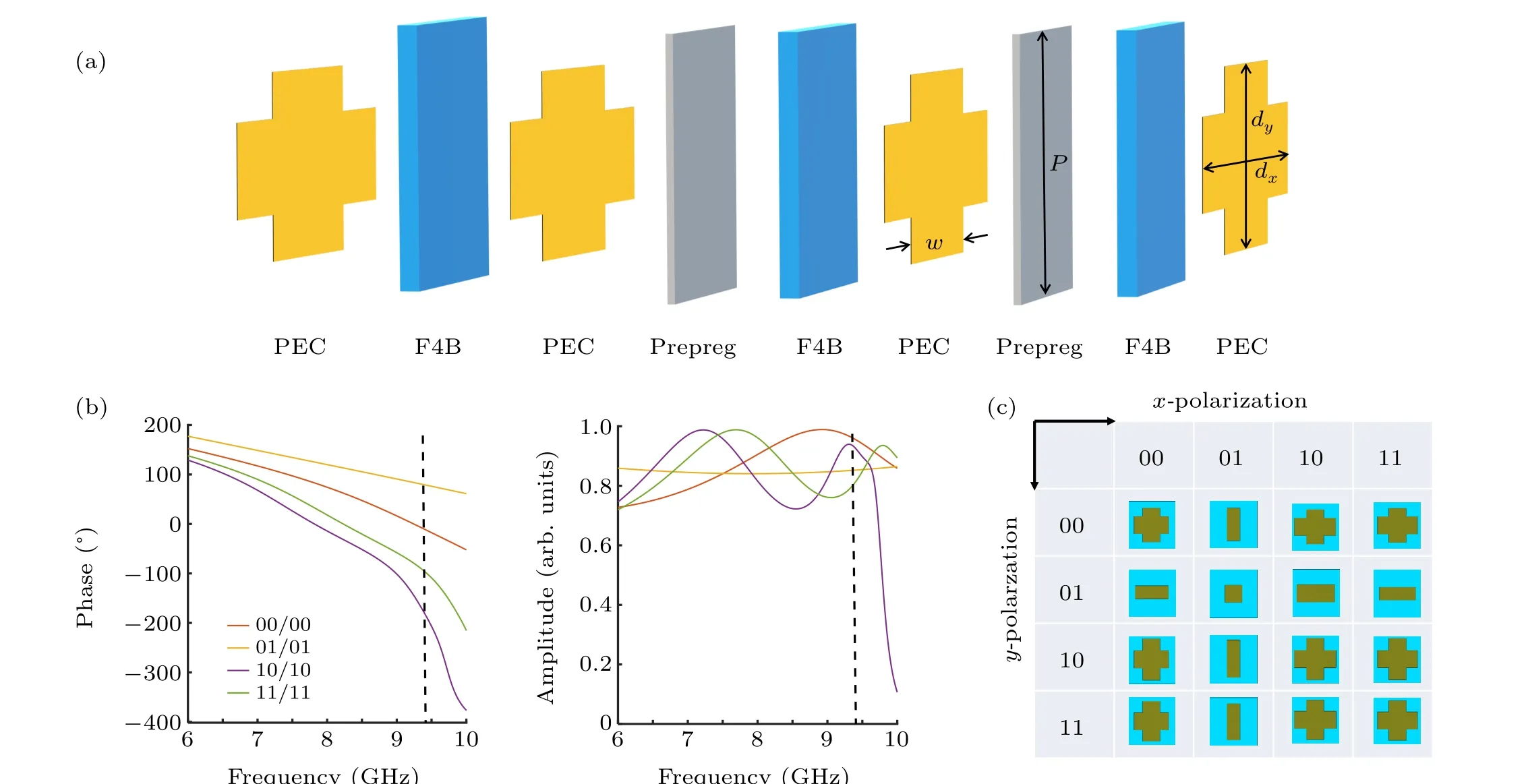
Fig. 1. Schematic diagram of the 2-bit transmissive anisotropic meta-atoms. (a) Perspective view of typical anisotropic meta-atom. (b) The phase and amplitude responses of four isotropic units“00/00”,“01/01”,“10/10”,“11/11”. The four structures are arranged along the diagonal in panel(c). (c)The 16 meta-atoms in 2-bit anisotropic coding metasurface.
Coding metasurfaces will be more widely applied in 6G communications,antennas and polarization manipulation than conventional designs.[68-74]In general, a single layer metasurface cannot achieve a full 2πphase modulation and a high transmission together.[75]Here,a four-layered cascaded metasurface with F4B dielectric spacer (εr=2.65, tanδ=0.001)is designed. For fabrication consideration,two prepreg layers(εr=4.2) are also added between the metallic sheet and the dielectric spacer to facilitate a tight combination of two adjacent F4B layers. The thicknesses of the dielectric spacer and the prepreg layer are 1.5 mm and 0.1 mm, respectively. The periodpof the meta-atom is 11 mm. As depicted schematically in Fig. 1(a), the meta-atom is composed of a stack of metallic cross-shaped patches, dielectric spacers and prepreg layers. The simulated electromagnetic responses of the coding metasurface were obtained by commercial software CST Microwave Studio. The phase profile ofx(y) polarization is sensitive to the length of the rod in the horizontal (vertical) direction while the length change along thex(y) direction has little effect on the phase profile ofy(x) polarization, thus the cross-shape structure is suitable for designing anisotropic metasurface.[65,67]The 2-bit anisotropic coding metasurface can be directly achieved by adjusting the lengths(dxanddy) and width (w) of the cross-shaped meta-atom.dx=dy=7.9 mm,4 mm,9.54 mm,and 9.1 mm are selected to construct four different meta-atoms locating along the diagonal in Fig.1(c),while the width(w)of both the horizontal and vertical metal patches is 4 mm in these four meta-atoms.The phase and transmission amplitudes of four meta-atoms forxandypolarization are the same since the four meta-atoms in the diagonal are isotropic. The phase responses of four meta-atoms are 77.83°,-13.75°,-101.5°, and-192°. Obviously, two adjacent meta-atoms have nearly 90°phase differences. The transmission amplitude is above 0.82, as depicted in Fig.1(b). With respect to the required phase profiles of incidentx- andy-polarized waves, digital meta-atoms are comprehensively considered. All the 16 meta-atoms involving in 2-bit anisotropic coding metasurface is shown in Fig. 1(c)and their parameters are listed in Table 1.
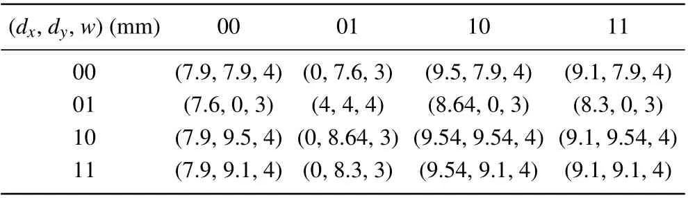
Table 1. Structure parameters of 2-bit anisotropic coding metasurface.
As for the 2-bit coding metasurface, 90°phase difference of the digital meta-atom more contributes to the performance of the coding metasurface rather than the absolute phase value.[31]The 2-bit coding metasurface has four different digital states with 90°phase difference that are labeled as“00”, “01”, “10”, and “11”. The expression of “00/01” indicates the combination of different digital states (transmission phase)under the illumination ofx/ypolarized waves. Although the 16 meta-atoms illustrated in Fig. 1(c) do not fulfil the absolute phase value of the digital state, the prerequisite of 90°phase difference enables them to form 2-bit coding metasurface. Therefore, anisotropic coding metasurface can be proposed to independently manipulate two orthogonal polarizations, next a polarization beam splitter and an OAM generator will be investigated.

Fig.2.Simulated 3D far field pattern(a)-(c)and 2D radiation pattern(d)-(f)of the polarization beam splitter.θ and φ are the elevation and azimuth angles of an arbitrary direction. Panels(a)and(b),(c)and(d),and(e)and(f)show the results of the polarization beam splitter under the illumination of x polarization,y polarization and 45° linear polarization respectively. Panels(d)and(e)show the results in φ =180° and φ =270° planes. Panel(f)shows the gain maps of x and y polarizations in φ =180° and in φ =270° planes,respectively. The transmitted waves of x and y polarization refract into different directions. The deviation angle in panels(d)-(f)is 21°.
3. Polarization beam splitter
To demonstrate flexible EM wave manipulation of anisotropic 2-bit coding metasurface, a polarization beam splitter is designed to separatexandypolarized waves into different directions. As shown in the following matrixM,the anisotropic coding metasurface is encoded with the same coding sequence“00”,“01”,“10”,“11”along thexandydirections for incidentxandypolarized waves,respectively;

To minimize the coupling effect between adjacent unit cells,each digit is represented by a 2×2 super unit cell. Figure 2 shows 3D and 2D results forx,yand 45°linear polarized waves propagating along the +zdirection, respectively. As shown in Figs. 2(a) and 2(b), incidentxpolarized EM wave is refracted into thexozplane and incidentypolarized EM wave is refracted into theyozplane. If the incident wave is 45°linear polarized,x- andy-polarized components are refracted into different directions,indicating that the anisotropic coding metasurface works well as a polarization beam splitter. The deviation angleθ(defined as the angle between the wave vector andzaxis)can be calculated asθ=arcsin(λ/Γ),
whereλis the wavelength in the free space andΓis the periodic length of the structure. At 9.44 GHz,the calculated deviation angleθof the coding metasurface is about 21°. This phenomenon can be clearly seen in Figs. 2(e) and 2(f) and the main beam is anomalously refracted along the directionθ=21°. The calculated and simulated results show a good agreement with each other. The intensities and deviation angles ofxandypolarized EM waves are exactly the same. The proposed polarization beam splitter is capable of totally separatingx-andy-polarization components.
4. OAM beam generator
Anisotropic metasurfaces are usually utilized to manipulate the polarization state of EM wave. Besides the polarization manipulation, the phase profile can also be controlled by anisotropic metasurface to achieve some novel applications such as holography,[21]meta-lens,[64]RCS reduction,[76]and vortex beam.[77]Here, an anisotropic coding metasurface is designed to achieve both polarization conversion and the phase control of a normally incident plane wave. In order to obtain 90°phase difference betweenx- andy-polarized waves and their equal transmittance, 4 coding meta-atoms “00/01”,“01/10”, “10/11”, and “11/00” are adopted among the aforementioned 16 elements. Actually, such anisotropic coding metasurface can be regarded as a quarter wave-plate and convert incident 45°polarized wave to right-handed circular polarization. More importantly, right-handed circular polarization waves outputting from these 4 coding meta-atoms have 90°phase difference one by one and high transmission is achieved in the vicinity of 9.44 GHz, illustrated in Fig. 3. It can be seen that the transmission amplitude can reach above 0.84 in all cases and the phase difference between two adjacent meta-atoms is always nearly 90°.
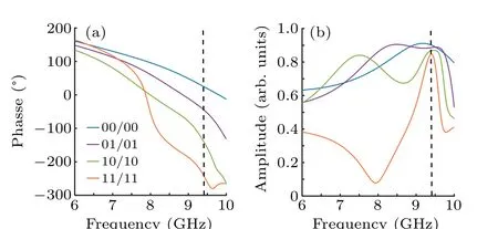
Fig. 3. (a) The phase responses of right-handed circularly polarized wave emerging from 4 coding meta-atoms “00/01” (blue line), “01/10” (orange line),“10/11”(green line),and“11/00”(purple line). (b)The magnitude responses of 4 coding meta-atoms. In panels (a) and (b) the incident wave is 45° linearly polarized.
The coding metasurface with 4 meta-atoms is proposed to design an OAM beam generator withl=2. The designed coding metasurface is shown in Fig. 4(a), which is composed of 40 meta-atoms along both thexandydirections. The incident 45°linearly polarized wave propagates along the+zdirection.The simulated near field results of circular polarized transmitted field are shown in Figs.4(b)and 4(c). The observed area of 450 mm×450 mm is placed 200 mm away from the surface of the coding metasurface. As expected, there is a null point in the center of the intensity profile and the phase profile exhibits 4πphase rotation in the azimuth direction. Thus,the generation of the OAM wave withl=2 is confirmed by both doughnut shape magnitude and spiral phase distribution. The resolution of the OAM field can be improved using multi-bit coding metasurface.
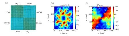
Fig.4. (a)The configuration of the coding metasurface for generating an OAM beam with l=2. The simulated(b)magnitude and(c)phase profiles at the plane 200 mm away from the metasurface surface.
To experimentally verify the OAM performance of the proposed coding metasurface, a 440 mm×440 mm coding metasurface was fabricated by standard PCB fabrication technique. The fabricated coding metasurface is shown in Fig. 5(a), which consists of 40×40 meta-atoms. The near field experimental configuration is shown in Fig. 5(b). The experiment was conducted in a microwave anechoic chamber.The linear polarized horn antenna was placed 600 mm away from the coding metasurface to launch a quasi-plane wave.Thexandypolarized electric fields 200 mm away from the coding metasuface were recorded by the probe. Thus, the right handed circularly polarized EM field can be obtained byEcirc=Ex+iEy. The probe scanned the sample plane with 45 scanning points and the interval between each scanning point was 10 mm(~λ/3).

Fig.5. (a)The fabricated sample and(b)the measurement setup.
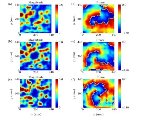
Fig. 6. The measured magnitude and phase distributions of the emerging OAM beam in the x-y plane 200 mm away from the metasurface surface. The coding metasurface is illuminated by normally incident 45° linear polarization at(a)-(d)9 GHz,(b)-(e)9.6 GHz,(c)-(f)10 GHz.
The measured near field patterns of the fabricated coding metasurface at 9 GHz, 9.6 GHz, and 10 GHz are shown in Fig.6. It can be seen in Figs.6(a)-6(c),the doughnut shaped magnitude patterns are obtained and the 4πspiral phase in Figs. 6(d)-6(f) indicates that the topological charge isl=2.Simulation and experiment results are basically in a good agreement with each other, despite a slight fluctuation at the working frequency. The fabricated metasurface experimentally shows an acceptable performance in three frequencies.The discrepancy and flaw may be caused by the imperfect sample fabrication and the finite sample size. Besides the predesign working frequency, the coding metasurface exhibits a good performance of the OAM beam withl=2 in the frequency range of 9 GHz-10 GHz. It is known that the propagation phase caused by resonance mechanism always have a narrow working bandwidth. Thus, it is useful for the coding metasurface to work in a relatively wide bandwidth.
5. Conclusion
In summary, we have designed a transmission-type anisotropic coding metasurface composed of four layered cascaded metallic patterns. Polarization beam splitter based on coding metasurface has been numerically verified to completely refract two polarizations into two different directions.The anisotropic coding metasurface has been experimentally demonstrated to realize an OAM beam withl=2 of righthanded polarized wave, benefiting from linear-to-circular polarization conversion and the phase profile modulation. This work may pave a possible way to design a transmission type of direct-modulation wireless communication system and novel coding metasurfaces.
Acknowledgments
Project supported by the National Natural Science Foundation of China (Grant No. U1931121), the Natural Science Foundation of Heilongjiang Province in China(Grant No. ZD2020F002), 111 Project to the Harbin Engineering University (Grant No. B13015), the Fundamental Research Funds for the Central Universities (Grant Nos. 3072021CFT2501 and 3072021CF2508), and the Postdoctoral Scientific Research Developmental Fund of Heilongjiang Province,China(Grant No.LBH-Q9097).
- Chinese Physics B的其它文章
- Characterizing entanglement in non-Hermitian chaotic systems via out-of-time ordered correlators
- Steering quantum nonlocalities of quantum dot system suffering from decoherence
- Probabilistic quantum teleportation of shared quantum secret
- Spin–orbit coupling adjusting topological superfluid of mass-imbalanced Fermi gas
- Improvement of a continuous-variable measurement-device-independent quantum key distribution system via quantum scissors
- An overview of quantum error mitigation formulas