
Optoelectronic oscillator-based interrogation system for Michelson interferometric sensors
2022-09-24 07:59LingLiu刘玲XiaoyanWu吴小龑GuodongLiu刘国栋TigangNing宁提纲JianXu许建andHaidongYou油海东
Chinese Physics B 2022年9期
关键词:海东
Ling Liu(刘玲) Xiaoyan Wu(吴小龑) Guodong Liu(刘国栋) Tigang Ning(宁提纲)Jian Xu(许建) and Haidong You(油海东)
1Key Laboratory of All Optical Network and Advanced Telecommunication Network,Ministry of Education,Institute of Lightwave Technology,Beijing Jiaotong University,Beijing 100044,China
2Institute of Fluid Physics,China Academy of Engineering Physics,Mianyang 621900,China
3Key Laboratory of Science and Technology on High Energy Laser,China Academy of Engineering Physics,Mianyang 621900,China
4Qingdao Agricultural University,Qingdao 266109,China
Keywords: interrogation system,optical fiber sensor,optoelectronic oscillator
1. Introduction
Optical fiber sensors, with their advantages of light weight, compact size and immunity to electromagnetic interference,have been widely used in the diagnosis and monitoring of environmental conditions.[1-4]Among the various optical fiber sensors, the Michelson interferometer (MI), with its merits of ease of fabrication and high sensitivity, has applications in aeronautics, perimeter protection, bridge security monitoring and environmental condition monitoring.[5-8]However, MIs are conventionally interrogated by wavelength interrogation or Fourier transform, which requires an optical spectrum analyzer(OSA).[5]Therefore the interrogation resolution and speed are largely limited by the OSA;these limitations would in turn affect the performance of the sensing and measurement systems.
An interrogation scheme enabled by electrical approaches therefore has potential in applications requiring high resolution and high-speed interrogation. Generally, electrical domain-based interrogation of a MI can be implemented using the following three approaches. The first approach is based on intensity interrogation and is achieved by monitoring the power of the electrical signal output by a photodetector(PD).This is a simple approach. However, the linear interrogation range is limited by the small linear region of the interference fringe.[9]In addition, the interrogation accuracy would suffer from power fluctuations. The second approach, phasegenerated carrier-based interrogation,is achieved by monitoring the phase difference between the two signals transmitted in the two arms of the MI.A wide linear interrogation range and real-time interrogation can be enabled. Nevertheless, additional phase modulation of the reference signal is required,[6]increasing the complexity of the interrogation system. The third approach uses microwave photonic technologies, which convert the wavelength shift in the optical domain into a frequency shift in the electrical domain. For example, MI interrogation systems based on a periodic microwave photonic filter(MPF)have been proposed for temperature measurement[7]and displacement measurement,[8]but the use of a vector network analyzer(VNA)makes the system costly.
In this paper,we propose an interrogation system for a MI sensor. An optoelectronic oscillator (OEO), enabled by the sinusoidal nature of the MI interference fringe and a singlepassband MPF,are incorporated in the proposed interrogation system. The central frequency of the single-passband MPF,determined by the dispersive characteristics of the employed dispersive medium and the free spectral range (FSR) of the MI, mainly determine the frequency of the OEO. When the sensing arm of the MI is affected by the external physical factors to be measured,the interference fringe of the MI(i.e.,the FSR) would shift, leading to a frequency shift of the singlepassband MPF and ultimately the OEO.Such wavelength-tofrequency mapping therefore allows interrogation of the MI by tracking the frequency shift of the OEO. We also use a fiber ring resonator(FRR)for fine mode selection of the OEO,which further contributes to the stability of the OEO and the interrogation accuracy of the proposed interrogation system.Our proposed scheme brings high-performance interrogation with a wide linear range,high resolution and high speed,and can be used in applications in bridge security monitoring and industrial machinery sensing that require the measurement of strain or temperature.
2. Principle of operation
A schematic diagram of our proposed interrogation system is illustrated in Fig. 1. A homemade erbium-doped fiber amplifier (EDFA) is used as the broadband optical source(BOS)to provide a broadband optical signal with a full bandwidth of 60 nm. After transmission through a MI with two unbalanced arms,a sinusoidal broadband optical signal is obtained and then sent to a phase modulator(PM).After amplification in another EDFA and transmission through a dispersive medium(i.e.,a dispersion-compensating fiber,DCF),the modulated signal is transmitted through a FRR and then converted into a radio-frequency(RF)signal in a PD.The generated RF signal is amplified by an electrical amplifier(EA)and then divided into two paths via a divider. One path of the RF signal is fed back to the PM to form the OEO loop while the other is monitored via an electrical spectrum analyzer(ESA).
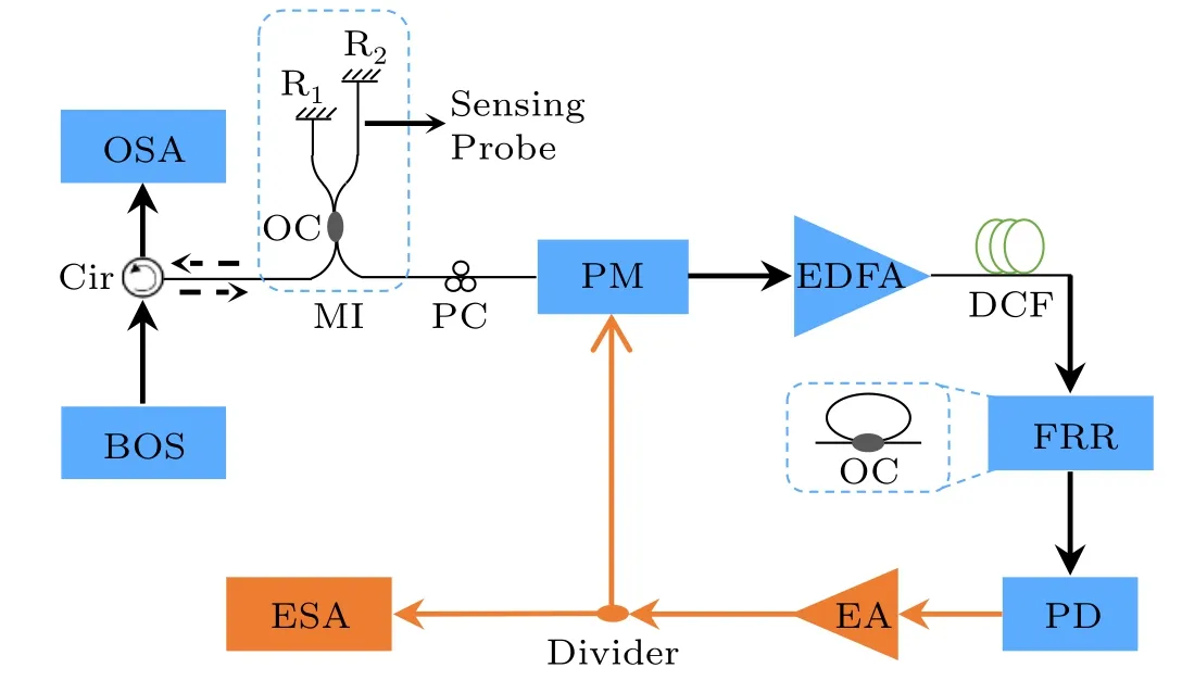
Fig.1. The proposed OEO-based interrogation system with the optical path shown in black and the electrical path shown in orange. BOS, broadband optical source; Cir, circulator; OSA,optical spectrum analyzer; OC,optical coupler;Ri,in-line reflector(i=1,2);MI,Michelson interferometer;PC,polarization controller; PM, phase modulator; EDFA, erbium-doped fiber amplifier; DCF, dispersion-compensating fiber; FRR, fiber ring resonator; PD,photodetector;EA,electrical amplifier;ESA,electrical spectrum analyzer.
The interrogation principle is described below. The transmission function of the MI can be written as

whereλis the wavelength of the broadband optical signal,nis the refractive index of the optical fiber composing the MI,ΔLis the length difference between the two arms of the MI.The FSR of the MI can be derived as ΔλFSR=λ2/2nΔL. Thus,the sinusoidal broadband optical signal with a FSR equal to ΔλFSRis obtained.
As reported in Moraet al.,[10]a single-passband MPF can be obtained by the joint operation of the sinusoidal broadband optical signal, an electro-optic modulator, a dispersive medium and a PD. The central frequency of the singlepassband MPF can be written as[10]

whereDis the total dispersion (ps/nm) of the DCF (and is fixed in this work). Hence,fMPFis uniquely linearly proportional to ΔλFSR. Similar to the mechanism of the optical fiber laser,[11]if the single-passband MPF alone is incorporated in a closed OEO loop and provides sufficient gain for the OEO loop, a RF signal whose frequency is equal tofMPFwould be obtained. Considering the 3-dB bandwidth of the singlepassband MPF and the single-mode oscillation of the OEO further, we used a FRR composed of an optical coupler and a length of optical fiber in our work. This introduces an additional infinite impulse response(IIR)-MPF with a periodic response and narrow bandwidth nature for each peak. The FSR of the FRR-based IIR-MPF can be expressed as[12,13]
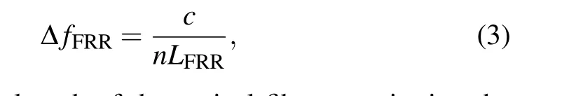
whereLFRRis the length of the optical fiber constituting the FRR,andcis the speed of light in a vacuum.Therefore,in this work, the open-loop response of the proposed OEO (i.e., the MPF response)would be determined jointly by the responses of the single-passband MPF and the FRR-based IIR-MPF.The frequency of the OEO is mainly determined byfMPFand is uniquely linearly proportional to ΔλFSR. The mode spacing of the OEO is jointly affected by the FSR of the FRR-based IIR-MPF and the lengthLDCFof the DCF.[13]Thereby, the wavelength-to-frequency mapping from the FSR ΔλFSRof the MI to the frequency of the OEO is established.
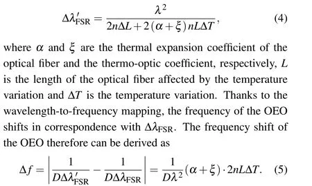
When the sensing arm of the MI is affected by external physical factors, the optical spectrum at the output of the MI would shift,leading to the variation of ΔλFSR.For temperature measurement,the varied FSR of the MI can be written as It can be found that the frequency shift of the OEO is linearly proportional to the variation of temperature when the total dispersionDof the DCF is fixed. In a similar way,the linear relationship between the variation of strain Δεand the frequency shift of the OEO can be expressed as Δf=(1-pe)2nLΔε/Dλ2, wherepeis the effective elastic-optic coefficient of the fiber. Hence,interrogation of the MI can be implemented by monitoring the frequency shift of the OEO.
3. Experimental results and discussion
The experimental setup of the proposed interrogation system is shown in Fig.1. A homemade EDFA with non-uniform spontaneous emission spectrum profile acts as the BOS. As observed by the OSA (Yokogawa, AD6370D) and shown in Fig. 2(a), a sinusoidal broadband optical signal with a ΔλFSRof 0.406 nm @ 1540 nm is obtained by the joint use of the BOS and the MI.Then, the sinusoidal broadband optical signal is modulated in the PM(Thorlabs,LN53S-FC)with a 3-dB bandwidth of 10 GHz and a half-wave voltage of 3.5 V. The DCF has a total dispersionDof-334 ps/nm and a lengthLDCFof around 2.4 km. After transmission through the DCF and amplification by another EDFA(Lion,BROADTRAN-16),the modulated optical signal is sent to the FRR,which comprises a 40:60 optical coupler and an optical fiber with a lengthLFRR(~500 m). Finally, the optical signal is converted into a RF signal in the PD (Thorlabs, RXM25AF) and amplified by an EA with a 3-dB bandwidth of 20 GHz and a typical gain of 26 dB. The generated oscillation signal is monitored by the ESA(Agilent,N9010A).
Joint operation of the sinusoidal broadband optical signal with ΔλFSR=0.406 nm and a DCF withD=-334 ps/nm leads to a single-passband MPF and the OEO,the responses of which are shown in Fig. 2(b). The frequencies of the singlepassband MPF and the OEO are in good agreement,although they are slightly different from the theoretical result based on Eq. (2). This frequency difference is mainly introduced by the instability of the MI reflection spectrum and the resulting measurement error of ΔλFSR. However, it would not greatly deteriorate the performance of the proposed interrogation system since the interrogation is not performed by tracking the wavelength shift. The 3-dB bandwidth of the single-passband MPF is around 396 MHz, which would lead to severe mode competition in the OEO.The FRR-based IIR-MPF is therefore introduced to mitigate this problem. The zoom-in spectrum of the OEO is shown in Fig. 3. Multiple modes with a spacing of 84 kHz and 429 kHz are observed simultaneously;the former is determined byc/nLDCF,and the latter is determined by ΔfFRR. It worth noting that,due to the FRR,single-mode oscillation of the OEO is guaranteed. A BOS with Gaussian or rectangular profile can also be used to narrow the 3-dB bandwidth of the single-passband MPF and mitigate the mode competition to some extent.
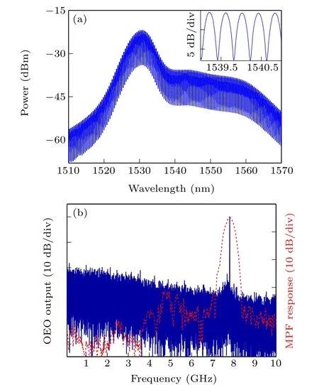
Fig.2. (a)Optical spectrum of the sinusoidal broadband optical signal measured at the output of the MI.Inset: zoomed-in view of the optical spectrum.(b) Measured OEO output (blue solid curve) and the single-passband MPF response(red short dash curve).
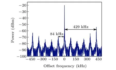
Fig. 3. Electrical spectrum of the OEO output (the resolution bandwidth is 0.75 kHz).
The performance of the proposed interrogation system in temperature measurement was evaluated. Part of the sensing arm was placed into a thermostatic water bath,and the lengthLof the optical fiber affected by the temperature variation was 106 cm. As shown in Fig.4,the frequency of the OEO shifted toward a higher-frequency regime with increasing temperature. This is consistent with the theoretical analysis described in Eq.(5). The linear relationship between the frequency shift of the OEO and the temperature variation can be learned from Fig.5. The temperature sensitivity and the correlation coefficient(R2)are 35.35 MHz/°C and 0.99,respectively.To further improve this sensitivity,Lcan be increased further. An appropriate decrease of the total dispersionDof the DCF would also help. Note that the frequency of the OEO changes from 7.8 GHz to 8.5296 GHz when the sensing head is moved from the test bench to the water bath. This is mainly due to the following two reasons. The first is the undesired disturbance and stretching of the MI arm during this movement. The second is the difference between room temperature and the water temperature. Nevertheless, when the optical fiber is fixed in the water bath at constant temperature,the OEO oscillates stably.Calibration is also required before the test.
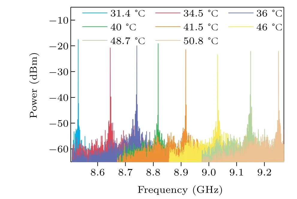
Fig.4. OEO outputs at different temperatures.
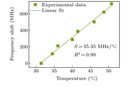
Fig. 5. Relationship between the temperature variation and the frequency shift of the OEO.
Next, the interrogation resolution and accuracy of the OEO-based interrogation system were investigated. Considering the use of the FRR and the corresponding mode spacing of 429 kHz, the theoretical interrogation resolution is 0.012°C,which can be improved by decreasing the FSR ΔfFRRof the FRR when the sensitivity is fixed; however, ΔfFRRcannot be decreased arbitrarily due to mode competition of the OEO.This places an upper limit on the interrogation resolution.The interrogation accuracy is evaluated by measuring the stability of the OEO. As shown in Fig. 6, when the proposed OEO-based interrogation system operates in a room environment over 30 min, the measured frequency and power fluctuations are 2.88 MHz and 1.24 dB, respectively. Hence, the temperature interrogation accuracy corresponds to 0.08°C.To improve this temperature interrogation accuracy further,the frequency fluctuation of the OEO should be minimized and an additional mechanism for further mode selection is required. Considering the OEO frequency tunable range of around 3 GHz(in this case)and the temperature sensitivity of 35.35 MHz/°C,the theoretical temperature interrogation range of the proposed interrogation system is around 84.9°C.However, in practice this interrogation range can be improved by broadening the frequency tunable range of the OEO and the 3-dB bandwidth of the photoelectric devices (e.g., the 3-dB bandwidth of the PM).
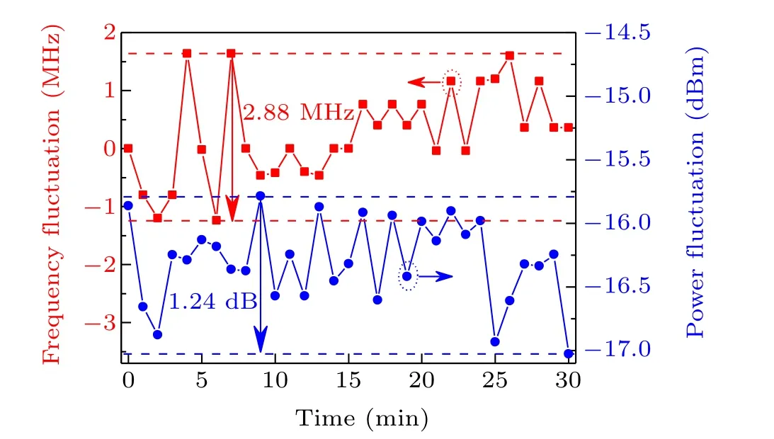
Fig. 6. Measured frequency fluctuation (red squares) and power fluctuation(blue circles)of the OEO.
A comparison of various temperature-sensing schemes and the interrogation approaches is shown in Table 1. Indeed,the interrogation resolution of our work should be improved compared with that in the work of Liet al.[4]However,unlike the wavelength interrogation scheme based on an OSA,[4,14,15]our work achieves wavelength-to-frequency mapping in the electrical domain, illustrating a potential method of highspeed interrogation that supports a wide linear interrogation range by avoiding overlapping of the measured spectrum.[18]Note that the interrogation speed reaches the MHz range when a digital signal processor unit is used.[19]Compared with a microwave photonics-based interrogation system using a VNA,[7,8]our work lowers the overall cost by avoiding the use of a VNA. In addition, compared with temperature measurement systems based on a Sagnac interferometer[13]or Mach-Zehnder interferometer,[17]a MI indeed provides a much higher sensitivity. The ultra-sensitive nature of a MI,in turn,implies that a MI is susceptible to undesired disturbance and the stability of the proposed interrogation system would be adversely affected to some extent. It is worth noting that when the sensing head is sensitive to other physical factors(e.g.,refractive index,strain),the proposed OEO-based interrogation system can be used not only for temperature measurement but also the measurement of these physical factors.[20]Such an OEO-based interrogation system with high resolution and high speed would support practical applications such as bridge security monitoring and industrial machinery sensing.
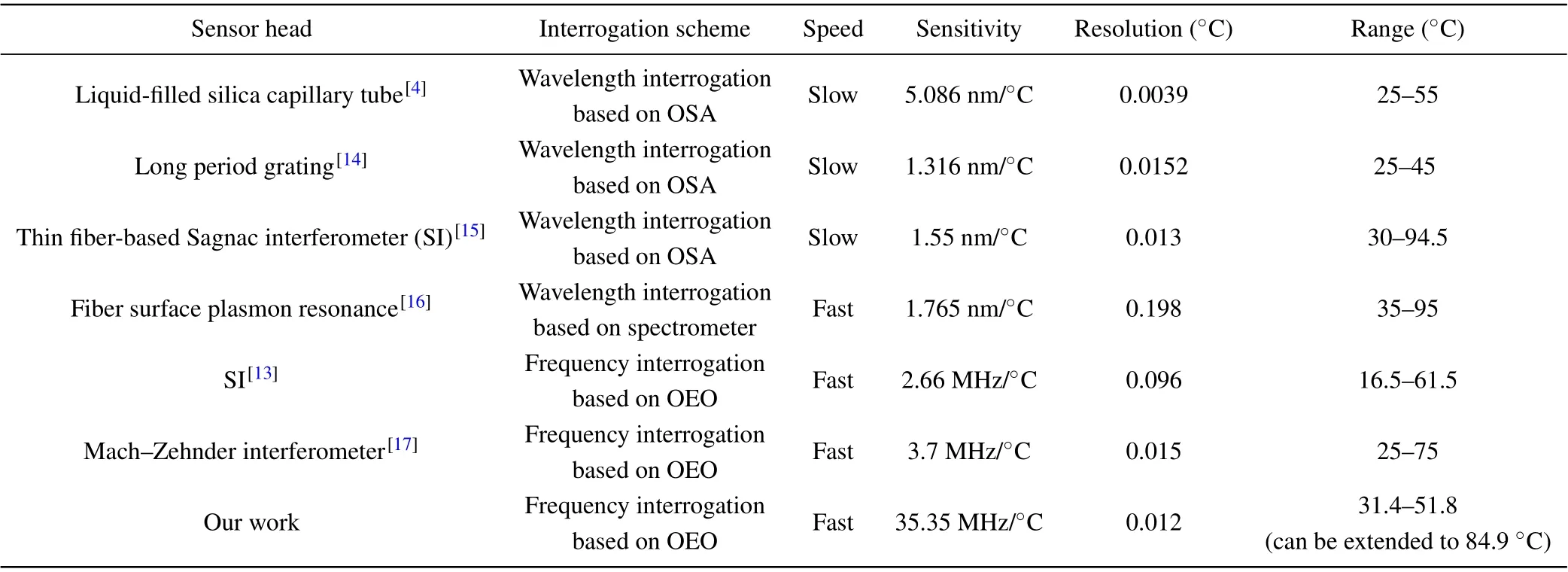
Table 1. Comparison of various temperature sensing schemes.
4. Summary
In summary, we have demonstrated a MI interrogation system implemented in the electrical domain. The fundamental idea is wavelength-to-frequency mapping enabled by the OEO.With the applied external physical factors,the frequency of the OEO changes with the FSR shift of the MI. Operational feasibility is verified for temperature measurement,and the temperature sensitivity,interrogation resolution and interrogation accuracy are 35.35 MHz/°C,0.012°C,and 0.08°C,respectively. The sensitivity can be improved by increasing the length of optical fiber affected by temperature. The interrogation resolution,although limited,is adjustable and can be improved by appropriately increasing the length of optical fiber constituting the FRR.
猜你喜欢
Chinese Physics B(2022年8期)2022-08-31
宝藏(2022年2期)2022-07-30
保健与生活(2022年8期)2022-04-08
黄河之声(2021年15期)2021-10-27
黄河之声(2021年12期)2021-10-25
宝藏(2021年8期)2021-09-15
中国篆刻(2019年5期)2019-12-10
云南大学学报(社会科学版)(2019年4期)2019-07-30
湛江文学(2016年8期)2016-12-08
专用汽车(2016年12期)2016-02-11

- Chinese Physics B的其它文章
- Characterizing entanglement in non-Hermitian chaotic systems via out-of-time ordered correlators
- Steering quantum nonlocalities of quantum dot system suffering from decoherence
- Probabilistic quantum teleportation of shared quantum secret
- Spin–orbit coupling adjusting topological superfluid of mass-imbalanced Fermi gas
- Improvement of a continuous-variable measurement-device-independent quantum key distribution system via quantum scissors
- An overview of quantum error mitigation formulas