
High-sensitivity refractive index sensors based on Fano resonance in a metal-insulator-metal based arc-shaped resonator coupled with a rectangular stub
2022-10-26 09:47ShubinYan闫树斌HaoSu苏浩XiaoyuZhang张晓宇YiZhang张怡ZhanboChen陈展博XiushanWu吴秀山andErtianHua华尔天
Chinese Physics B 2022年10期
关键词:秀山
Shubin Yan(闫树斌) Hao Su(苏浩) Xiaoyu Zhang(张晓宇) Yi Zhang(张怡)Zhanbo Chen(陈展博) Xiushan Wu(吴秀山) and Ertian Hua(华尔天)
1School of Electrical Engineering,Zhejiang University of Water Resources and Electric Power,Zhejiang–Belarus Joint Laboratory of Intelligent Equipment and System for Water Conservancy and Hydropower Safety Monitoring,Hangzhou 310018,China
2Hangzhou Hikvision Digital Technology Co.,Ltd.,Hangzhou 310018,China
3School of Electrical and Control Engineering,North University of China,Taiyuan 030051,China
Keywords: Fano resonance, metal-insulator-metal (MIM) waveguide, refractive index sensor, Fabry–Perot(F-P)cavity
1. Introduction
Surface plasmon polaritons (SPPs) can break through the diffraction limit and confine light in the sub-wavelength range.[1]When incident photons are coupled to the electrons on the conductor’s surface,SPPs will occur.Research on SPPbased metal-insulator-metal (MIM) waveguides has attracted the attention of researchers worldwide. In recent years, the SPP-based MIM waveguide has been applied in many areas,such as filters,[2–5]sensors,[6–9]and slow light systems.[10]These applications promote the rapid development of novel instruments.
The Fano resonance effect emerges from the coupling and interference of a non-radiative or continuum of the radiative spectrum.[11–13]Fano resonance exhibits an asymmetrical and ultra-sharp shape compared to the Lorentzian-shaped resonance. Because of its ultra-sharp transmission spectrum,Fano resonance has been applied in sensing equipment.[14,15]By detecting the small changes in ambient parameters, equipment based on Fano resonance can monitor changes in refractive index. In recent years, the design based on the structure of the MIM waveguide has been widespread. Qian Yang proposed a MIM waveguide structure comprised of a cross-shaped resonator, and the value of its sensitivity is 1075 nm/refractive index unit (RIU).[16]The Fano resonance of the structure can be tunable by changing the resonator’s length parameters. Jialing He designed a structure consisting of a ring resonator and a stub coupled with a MIM waveguide. The structure’s sensitivity is 1100 nm/RIU,and the figure of merit(FOM) reaches 42550.[17]Cheng Zhang proposed a simple waveguide-microring Fano structure and applied it to temperature measurement.[18]
This study proposes a MIM-based arc-shaped resonator coupled with a rectangular stub(MARS)structure. This structure can generate two tunable Fano resonances,including Fano resonance 1 (FR1) and Fano resonance 2 (FR2). The wavelength of FR1 is between 1400 nm and 2000 nm, and FR2 is between 800 nm and 1200 nm). To understand the formation principles of Fano resonances,this study adds three other structures to conduct comparative experiments. The size of the structure is controlled by hundreds of nanometers. The structure is sensitive to the changes in the surrounding environmental parameters and has the potential to be applied to various microsensors. The relationship between the structural parameters and Fano resonance is researched using the finite element method(FEM)based on the software CMOSOL Multiphysics 5.4. The simulation reveals that the sensitivity can reach 1900 nm/RIU and the FOM is 23.75. Refractive index sensors based on Fano resonance have proven to be efficient.However, due to the limits of etching precision, it is difficult to precisely take control of the distancedand manufacture the MARS resonance cavity system.[19,20]This study mainly analyzes the formation principles and influencing factors theoretically and provides experience for manufacturing in the future.
2. Structure model and analysis method
A 2D illustrative diagram of the MARS structure proposed in this study, composed of a MIM with a rectangular stub coupled with the arc-shaped resonant cavity,is shown in Fig.1. The white part represents the dielectric layer of air,and the green part indicates metal Ag separately.R1andR2are the radii of the inner and outer arc-shaped resonator,respectively;r1,r2andr3are the radii of the three inner circles,respectively;dis used to describe the distance between the arc-shaped resonant cavity and MIM waveguide, andhindicates the height of the rectangular stub.
We choose the air as the isolators in the MIM waveguide and the arc-shaped resonator (nd=1). The Ag is chosen to be the metal-dielectric,whose relative dielectric constant(εd)can be described by[21]

Herein,ωrepresents the angular frequency of an incident wave in a vacuum, the infinite dielectric constantε∞is 3.7,the angular frequency of the plasma oscillationωpis equal to 9.1 eV(1.38×10¹⁶rad/s),and the frequency of electron collisionγis 0.018 eV(2.73×10¹³rad/s).
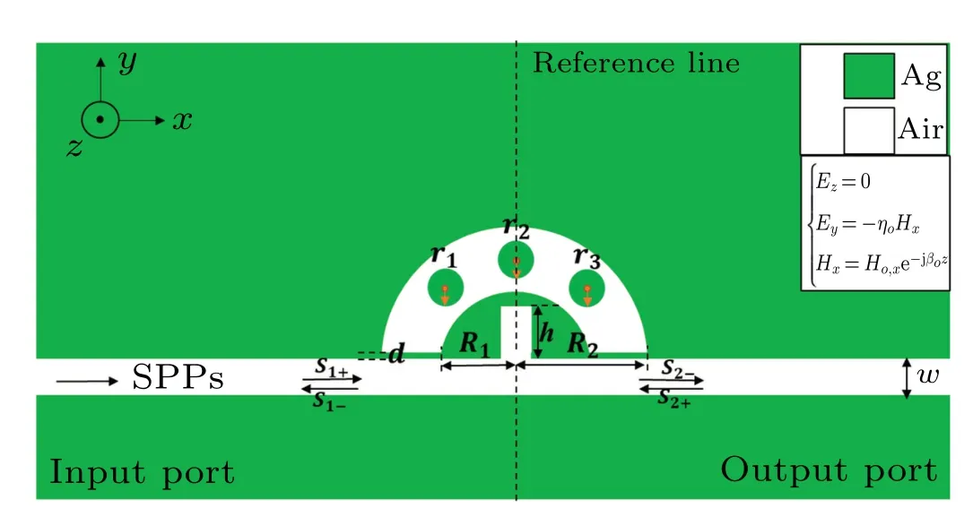
Fig.1. A 2D schematic of the structure comprising a MIM with a rectangular stub coupled with the arc-shaped resonant cavity.
To ensure that only the fundamental transverse magnetic(TM)exists in the MIM waveguide,wis set to 50 nm.The TM is characterized by the field amplitude decaying exponentially into both media away from the interface.[22]The electric field intensity of thez-axis andy-axis,and the magnetic field intensity of thex-axis are shown on the right-hand side of Fig. 1.The top and bottom boundaries are the perfectly matched layers(PMLs). With the help of FEM,[23]the transmission spectrum of the structure can be obtained. The trajectory of incident light is from the input portP1to the output portP2. Here,S1+,S1-,S2+andS2-are the scattering parameters of the incident light.
3. Simulation and results
To understand the formation principles of Fano resonances, this study adds three other structures, including a structure without the rectangular stub,a structure without three circles in the arc-shaped resonant cavity,and a structure without the arc-shaped resonant cavity.By comparing the different transmission spectrums of four structures, it is easy to learn about the formation process of Fano resonance. The transmission spectra of these four structures are shown in Fig.2.
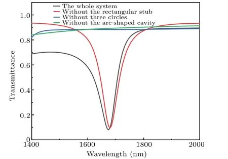
Fig.2. The transmission spectrum of the whole system(the black line),without the rectangular stub (the red line), without three circles in the arc-shaped resonant cavity (the blue line), and without the arc-shaped cavity(the green line).
From the principle of resonance formation, Fano resonance will be generated when the continuous wide-band state interacts with the discrete narrow-band state. It is the MIM waveguide that provides the continuous broad-bandstate mode.It can be seen that when adding the arc-shaped resonant cavity,the FR1 occurs at the wavelength of 1673.5 nm.The arc-shaped resonator generates the discrete narrow-band state mode in the formation of Fano resonance. In addition,by comparing the red curve with the black curve,it is easy to find that the FR2 is formed at the wavelength of 1070 nm when the rectangular stub is added. The rectangular stub can be approximately regarded as a Fabry–Perot (F-P) cavity. The air medium layer is sandwiched between two silver medium layers, which form a grating structure. This structure makes the directly transmitted light and the diffracted light interfere easily. It can be seen in Fig.3(a) that when the rectangular stub is added to the structure,stronger resonance occurs in the arcshaped resonant cavity and, at this time, SPPs are practically limited in the arc-shaped one.
When the three circles do not exist in the arc-shaped resonant cavity, two Fano resonances also form at 1030 nm and 1295 nm. The arc-shaped resonant cavity and the rectangular stub make two Fano resonances. In contrast,the circles inside the cavity make the dip of the Fano resonances move towards longer wavelengths and increase the wavelength differences between two Fano resonances. Meantime,the full width at the half maximum (FWHM) also becomes smaller, which is the reason for the more significant FOM value, and it is our goal to obtain the significant FOM value.

Fig.3. The distribution of the Hz field in the dip of 1070 nm: (a)withand(b)without the rectangular stub.
To evaluate the sensing performance of the Fano system,two vital indices, including sensitivity and FOM, are introduced to the following experiments. The formulas of the sensitivity and FOM can be expressed by

Herein,Δλand Δnare the changes in the wavelength and refractive indices,respectively.
Figure 4(a)shows that when the refractive index changes from 1.00 to 1.05 at an interval of 0.01,the transmission spectrum shows a redshift. According to Eq.(2),whend=8 nm,h=100 nm,R1=176 nm,R2=110 nm,andr1=r2=r3=22 nm, the sensitivity reaches 1900 nm/RIU, which makes it efficient to detect changes in the refractive index.
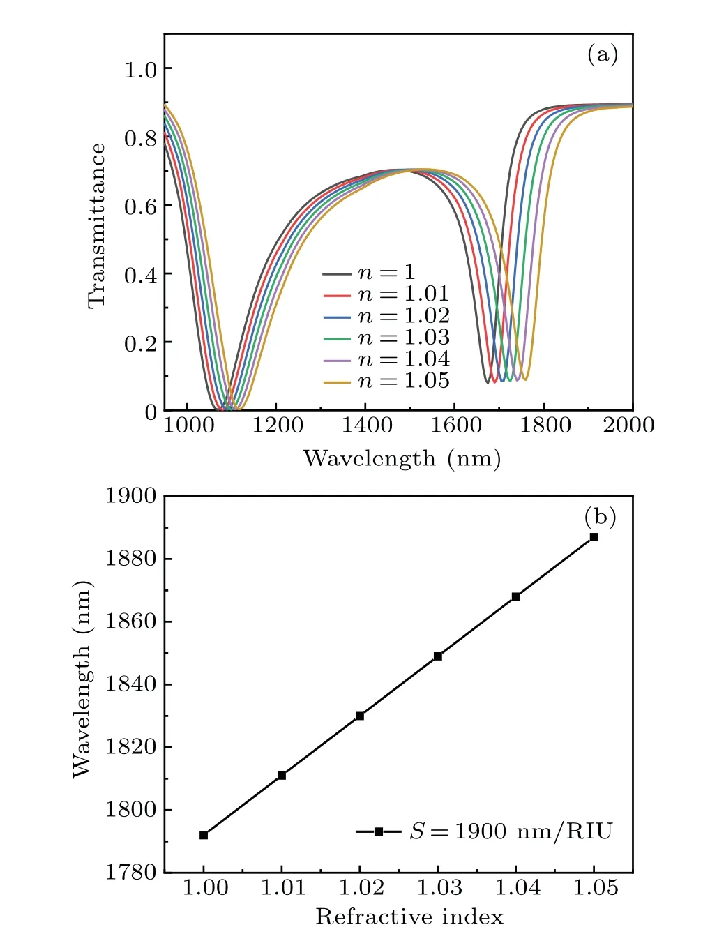
Fig.4. (a)The transmission spectrum shows a redshift when changing the refractive indices;(b)the sensitivity curve of Fano resonance.
The proposed structure can be used to detect the changes in the refractive index. Assuming the initial refractive index is 1.00, the value increases from 1.00 to 1.05 at an interval of 0.01. The simulated transmission spectrum is shown in Fig.4(a),from which it is evident that the dip of the Fano resonance moves to a longer wavelength. The parameterScan be used to reflect the performance of the structure. The structure designed in the article has a sensitivity of 1900 nm/RIU,which means the dip in the wavelength moves at a step of 19 nm.Therefore, we can calculate the refractive index according to the value of the resonance dip.
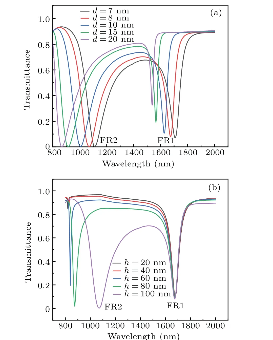
Fig. 5. The transmission spectrum of (a) different coupling distances between the arc-shaped resonant cavity and MIM waveguide d;(b)different heights of the rectangular stub h.
Next, the effects of changing several parameters such asd,h,R,andrare researched. Due to the more significant sensitivity value of FR1,FR1 is a primary study focus to help understand the effects of different parameters on the structure’s sensitivity.As shown in Fig.5(a),whendincreases from 7 nm to 20 nm,the dip of FR1 increases sharply,while both FR1 and FR2 show a blueshift. The parameterdhas a vital influence on the transmittance of FR1. In this study,dis chosen to be 8 nm. Whend=7 nm or smaller,the sensitivity curve linearity of the system is not good, limiting its application in sensors. Therefore, taking linearity and sensitivity into account,dis chosen to be 7 nm. As shown in Fig. 5(b), whenhincreases from 20 nm to 100 nm at an interval of 20 nm,the dip of FR1 is almost unchanged, while the dip of FR2 decreases sharply. The height of the rectangular stub mainly exerts its influence on FR2. According to the simulation results, the sensitivity reaches 1900 nm/RIU whenhis 100 nm. Considering the structural design,hshould not be greater than 100 nm.Finally,his chosen to be 100 nm.
In the resonator system of the MIM waveguide,the resonance wavelength of the peak can be calculated based on the standing wave theory as[24]
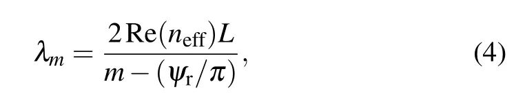
whereLis the length of the cavity,mis the antinodes number of the SPP wave,ψrdescribes the phase difference of the reflected beam,and Re(neff)represents the real part of the refractive index of a MIM waveguide.
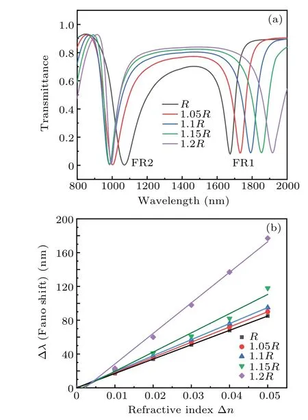
Fig.6. (a)The transmission spectrum of different R;(b)the sensitivity curve of Fano resonance when R changes from R to 1.2R.
In the following part, we set the parameterRas a constant,andRrepresents the initial values ofR1,R2,r1,r2,andr3. The initial values ofR1andR2are set to 160 nm and 100 nm, respectively. Ther1,r2, andr3initial assignments are all 20 nm. WhenR1,R2,r1,r2,andr3vary fromRto 1.2R,the dip of FR1 is redshifted, while the dip of FR2 moves to shorter wavelengths. As mentioned earlier, the generation of FR1 is relevant to the arc-shaped resonant cavity. When the radius increases to 1.2R, equal to the more significant value of the length of the arc-shaped resonant cavity,the FR1 shows a redshift, and the phenomenon is consistent with Eq.(4). In addition,as previously analyzed,the generation of FR2 is related to the rectangular stub. As the radius increases,the distance between the rectangular stub and the arc-shaped resonant cavity becomes more significant and is not helpful for the arcshaped resonant cavity to generate a strong resonance. Therefore, the dip of FR2 shows a blueshift. The sensitivity fitting curves of different radii are drawn out based on the experimental data, as shown in Fig.6(b). Although the Fano resonance becomes more sensitive to the refractive index when the radius increases to 1.2R,the sensitivity curve becomes more nonlinear when the radius is more significant than 1.15R. Therefore,regarding the sensitivity and linearity, the radius is 1.1R, and the sensitivity reaches 1900 nm/RIU.At this time,R1,R2,r1,r2, andr3are 176 nm, 110 nm, 22 nm, 22 nm, and 22 nm,respectively.
The symmetry of the structure also has an important influence on the curve. When the circles inside the arc-shaped resonant cavity are removed partly or entirely,the blueshift of FR1 will occur. However,it is noteworthy that the middle one of the three circles is more relevant to FR1. Compared with when the left or right circle is removed,the dip of FR1 moves to shorter wavelengths when the middle one is removed. This fact accounts for the theory that the middle circle in the arcshaped circle is helpful for the reinforcement of FR1. This is the subtlety of the structure designed in this study.

Fig.7. The transmission spectrum when one or two circles are removed inside the arc-shaped resonance cavity.
4. Conclusion and perspectives
This study presents the MARS structure,which can generate two Fano resonances originating from two different mechanisms.Using the FEM based on the software CMOSOL Multiphysics 5.4, the relationship between the structural parameters and Fano resonance is researched. To understand the formation principles of Fano resonances,this study adds three other structures to conduct comparative experiments. It has been found that the parameterdhas a vital influence on the transmittance of FR1,while the height of the rectangular stub mainly exerts its influence on FR2. WhenR1,R2,r1,r2, andr3increase, FR1 shows a redshift. In addition, the symmetry of the structure has an important influence on the curve,and the middle circle in the arc-shaped circle is helpful for the reinforcement of FR1. The structure has the advantage of being sensitive to the changes in the refractive index, which is promising for application in various microsensors. The simulation reveals that the sensitivity can reach 1900 nm/RIU and the FOM is 23.75.
Acknowledgements
System numerical simulation was provided by COMSOL,INC.
The work was supported in part by the National Natural Science Foundation of China (Grant Nos. 61875250 and 61975189), the Zhejiang Provincial Natural Science Foundation of China (Grant Nos. LD21F050001 and Y21F040001),the Key Research Project by Department of Water Resources of Zhejiang Province (Grant No. RA2101), the Key Research and Development Project of Zhejiang Province(Grant No.2021C03019),the Key R&D Projects of Shanxi Province(Grant Nos. 201903D421032 and 01804D131038), and the Scientific Research Foundation of Zhejiang University of Water Resources and Electric Power(Grant No.xky2022032).
猜你喜欢
汽车实用技术(2022年15期)2022-08-19
鸭绿江·华夏诗歌(2021年10期)2021-05-12
商讯·公司金融(2019年26期)2019-09-10
长江文艺(2019年8期)2019-08-07
重庆与世界(2019年2期)2019-04-11
当代党员(2018年17期)2018-09-06
东坡赤壁诗词(2017年3期)2017-07-05
东坡赤壁诗词(2017年3期)2017-07-05
广西民族研究(2016年4期)2016-11-05
祝你幸福·知心(2016年3期)2016-03-29
- Chinese Physics B的其它文章
- Formation of high-density cold molecules via electromagnetic trap
- Dynamics of molecular alignment steered by a few-cycle terahertz laser pulse
- Terahertz spectroscopy and lattice vibrational analysis of pararealgar and orpiment
- Molecule opacity study on low-lying states of CS
- Finite-time Mittag–Leffler synchronization of fractional-order complex-valued memristive neural networks with time delay
- Ultrafast Coulomb explosion imaging of molecules and molecular clusters