金属硫化物基钾离子电池负极:储存机制和合成策略
2022-11-24 11:16杜忆忱张壮壮徐一帆包建春周小四
物理化学学报 2022年11期
杜忆忱,张壮壮,徐一帆,包建春,周小四
南京师范大学化学与材料科学学院,南京 210023
1 Introduction
Advanced large-scale energy storage technology is urgently needed for the efficient and diversified utilization of new energy in the new era1–4. However, lithium resources, the raw material vital to the development of this technology, are highly limited and unevenly distributed in the crust, restraining the growth of large-scale energy storage and electric vehicle technology5–8. By contrast, potassium ion, with similar chemical property and storage mechanism to that of lithium ion, is abundant in the earth’s crust and more widely distributed9,10. Therefore, the development of low-cost potassium-ion batteries (PIBs) are of great importance to the application of large-scale energy storage and smart grid11–14.
Anode materials help break the performance bottlenecks of high-performance batteries, thus becoming the key to the development of these batteries15,16. However, due to the large ion size of K+, the repeated potassiation/depotassiation in the bulk phase of anode will lead to the collapse of the ion structure.Hence, many anodes with high theoretical capacity eventually display poor cycle and rate performance during the charge/discharge process17–20. Therefore, to design anodes with long cycle life and fast discharge/charge process and to obtain high-energy-density and high-power-density PIBs are now the core issues to be addressed21–24.
PIB anodes have four reaction mechanisms, including intercalation/deintercalation reaction (hard carbon)25–28,conversion reaction (Fe2O3, FeS2, FeSe2, NiSe2, etc.)29,30,alloying reaction (red phosphorus, antimony, germanium, tin,etc.)31,32and conversion-alloying reaction process (GeO2, SnO,SnS2, SnSe2, GeSe2, etc.)33,34. Theoretically, anodes based on the conversion reaction and conversion-alloying reaction mechanisms have smaller volume expansion during cycling than the alloying-type anodes, whereas their capacity (larger than 400 mAh·g−1) is larger than the intercalation-type anodes35–37. Metal chalcogenides (MCs) follow the conversion or conversion-alloy mechanism in the process of potassium storage, indicating their great potential for K+storage38–41.
MCs mainly include metal sulfides, selenides and tellurides,among which metal sulfides (MSs) have been widely used in the research of lithium-ion and sodium-ion batteries due to their high theoretical specific capacity and low potential42–45. They are also highly promising for PIBs. Moreover, compared with metal oxides of the same family, the larger ionic radius of S makes the M−S bond weaker than the M−O bond, contributing to better electronic conductivity and lower ion diffusion barriers46–48.Nevertheless, the practical application of MSs anodes is also limited. For example, the electrical conductivity of this material is still not satisfactory enough, and the by-product polysulfides generated during the charge/discharging undergo dissolution and shuttle effects, resulting in the loss of active materials. In addition, the volume of the material structure expands and shrinks drastically during cycling, which makes the active components pulverize and fall off, eventually leading to rapid capacity decline and low cycle stability44,49–51.
Through the research of the specific potassium storage mechanism and reaction kinetics process of MS anodes, the indepth analysis of the challenges the material currently faces, and the rational design of the synthesis methods of metal sulfides or metal sulfide-based composites with unique structures (such as core-shell, porous and hollow structure), the disadvantages of MSs can hopefully be overcome and the anode materials with excellent electrochemical performance can finally be obtained.In this review, research on K+storage mechanisms, relevant problems and synthesis methods of MSs as the PIB anodes are summarized (Fig. 1). Considering the existing reviews on MSs for PIBs, this review mainly focuses on the synthetic methodology of the unique-structure MSs with superior K ion storage capacity. More research on these methods is also needed to implement the mass production and practical application of MSs in the future.
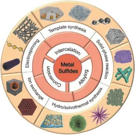
Fig. 1 Schematic illustration of typical reaction mechanism and synthesis of metal sulfide-based PIB anodes.
2 Potassium storage mechanisms of MSs
There are four reaction mechanisms of metal sulfide anodes:intercalation/extraction reaction, conversion reaction, alloying reaction and conversion-alloying reaction. At the beginning of discharge, potassium ions intercalate into the bulk structure of the MSs, which exists in both layered and non-layered sulfide anodes52–54. During further discharge, there is sufficient space between layers of the layered MSs to accommodate a large amount of potassium ions. Hence, the intercalation reaction mechanism is mainly followed. Furthermore, this process changes the oxidation state of the metal, but has little effect on its structural framework. In contrast, there are two situations of the reactions of non-layered MSs. For sulfides in which the metal is electrochemically inactive (such as MoS2, FeS2, ZnS, and V5S8)55–60, conversion reactions happen during further discharge. Metal sulfides react with K+to form metal element and thermodynamically stable potassium sulfide. For MSs in which the metal is electrochemically active (mainly Ge, Sn, Sb,and Bi sulfides)61–65, the conversion and alloying reaction happen in sequence, and finally potassium sulfide and intermetallic compound KxMywith different stoichiometric ratios are formed. Due to the additional alloying storage process,this kind of material shows higher theoretical specific capacity.However, since the crystal structures formed by different elements are very different, these crystals undergo structural remodeling accompanied by a large volume expansion upon KxMyformation. At the same time, the formation of KxMyin crystalline materials also leads to uneven volume changes in the two-phase boundary region, resulting in the cracking or pulverization of the active particles, which eventually causes the contact loss between the active particles and the conductive additives and the sharp decrease of the reversible capacity.Therefore, it can be concluded that MSs with alloying reaction processes tend to exhibit poor cycling performance.
The detailed reaction processes of PIBs anodes vary with their crystal phases, structures and depths of discharge. The specific reaction process tends to be more complex. For example, Qin et al.66prepared an organic-inorganic composite material,PASP@SnS2@CN, as the anode of PIBs and investigated its potassium storage mechanism in the voltage range of 0.01–3 V by in situ X-ray diffraction (XRD). The results showed that the anode underwent a total of six stages and ten steps upon K+insertion/extraction. During the discharge process, the reactions lasted through stages 1 (3.0–1.25 V, 5SnS2+ 2K++ 2e−= K2S5+5SnS), 2 (1.25–0.55 V, K2S5+ 8K++ 8e−= 5K2S, SnS + 2K++2e−= K2S + α-Sn), and 3 (0.55–0.01 V, 23Sn + 4K++ 4e−=K4Sn23, K4Sn23+ 19K++19e−= 23KSn), including multi-step conversion and alloying reactions. During the charging process,the reaction proceeded reversibly, and the discharge products were consumed to regenerate the original materials. The abovementioned processes lasted through stages 4, 5, and 6,respectively. The weakened diffraction peaks of SnS2and SnS indicated that the reaction was partially reversible.
3 Challenges
Despite the impressive progress made, the research of MSs is still emerging and there are many issues to tackle. The main challenges faced by current MS anodes can be concluded into the following five aspects67,68
(1) The dissolution of polysulfide and shuttle effects:potassium polysulfides are formed during the deep potassiation process in most metal sulfides, which can deteriorate the electrochemical performance of the material because of the dissolution of polysulfides in electrolyte and detrimental shuttle effects. The dissolution of polysulfides causes the loss of active materials, eventually resulting in poor reversibility. Shuttle effects refer to the migration of the dissolved polysulfide to K metal and its reaction with K to generate K2S, which not only block K+diffusion channels but also lead to the loss of MSs in the half-cell, thus decreasing the capacity, lowering the columbic efficiency and shortening the cycle life.
(2) Sluggish charge and ion transfer kinetics: MSs possess relatively low ion-diffusion coefficient and electronic conductivity. Owing to the large size of K+, these problems are especially aggravated when MSs are used as anodes for PIBs,giving rise to sluggish reaction kinetics, low utilization efficiency of active sites as well as large electrochemical polarization. As a consequence, obvious capacity decrease can be detected at high rates in the test.
(3) Severe volume variations during cycling: The electrode materials undergo volume expansion resulting from the largesized K ions during potassiation/depotassiation cycles. It has been reported that graphite has ~61% volume change after potassiation, which is six times larger than that after lithiation.The MS anodes undergoing alloying reactions show much greater volume variations upon cycling with ~400% for Sb2S3and ~681% for Sn4P3. Such continuous huge volume changes upon cycling bring about irreversible phase change, destruction of the SEI and pulverization and delamination of the electrode from the current collector, leading to capacity fading in the end.
(4) Serious side reactions: Solvents in the electrolyte are easily reduced on the surface of the anode due to the low voltage of K+/K. This leads to the consumption of the electrolyte and even the drying out of the electrolyte after long-term cycling,dramatically intensifying the electrode polarization and decreasing the cycling stability of the anode.
(5) Instable SEI layer: The repeated volume expansion and contraction destroy the existing SEI produced from initial stages.The exposed MSs react with K ions to generate a new SEI layer,which aggravate the consumption of K ions and the related side reactions, thereby lowering the coulombic efficiency of electrode. Moreover, the low ionic conductivity and poor mechanical ductility of SEI is another problem of MSs.
4 Synthesis of metal sulfides
Recent progress of the fabrication of MSs for PIBs is summarized into five categories: template synthesis,hydro/solvothermal synthesis, solid-phase chemical synthesis,electrospinning synthesis, and ion-exchange synthesis69–71. By adjusting relevant parameters, various methods can be applied to design the structure, composition, particle size, atomic-level and heterostructure of the synthesized materials and engineer the 1D/2D/3D materials and MSxcomposites (MSx/graphite,MSx/carbonaceous, MSx/metal sulfides, MSx/metal oxides and ternary composites) with heteroatom doping, vacancy and/or expanded interlayer spacing, therefore improving the potassiumion storage properties67.
4.1 Template synthesis
The template method is the most popular one for the fabrication of MS anodes for PIBs. It can change the size,morphology and structure of nanomaterials thanks to the spatial confinement effect of the templates. It can also effectively alleviate the agglomeration of nanomaterials72. The template method can be mainly divided into hard and soft ones according to different properties of the template. The hard template maintains its specific structure by covalent bonds, mainly represented by anodized aluminum oxide (AAO), porous silicon,SiO2nanospheres, and polystyrene (PS). Compared with the hard template, the soft template cannot strictly control the shape and size of the product, but it has the advantages of various structures, simple operation and low cost. Soft templates are mainly bound by intermolecular or intramolecular soft forces.Common soft templates include biological macromolecules,surfactants, liquid crystals, micelles and so on. Over the past years, many researchers have used template method to prepare MSs as the anode for PIBs73,74. For example, few-layered V5S8nanosheets wrapping a hollow carbon sphere were fabricated via a facile hollow carbon template induced method54. V5S8, with its lamellar structure, has been considered as a good host for K+because of its super interlayer spacing (1.132 nm) and metallic property. Nevertheless, since traditional liquid exfoliation technique is time-consuming and unproductive, Li and his coworkers utilized hollow carbon as a template to induce the formation of VS4particles and meanwhile prevented them from aggregating. The synthesized particles were then converted to ultrathin few-layered V5S8in the subsequent calcination. Due to the synergistic effect between V5S8and hollow carbon which leads to the ultrathin nanosheet structure, superior reaction kinetics and reversible phase transformation during cycling,such hollow carbon-templated 2D V5S8nanosheets are regarded as the promising material for high-performance PIBs.
Compared with the traditional soft and hard template methods,the template in the self-template method not only supports the frame, but also directly participates in the formation of nanomaterials. Therefore, the self-template method features fewer reaction steps, less template required, advantageous nanostructure design and better component optimization77–80. In the application of this method, MoO3-EDA nanowires were used as the template for Mo2S anodes75. As can be seen in Fig. 2a–d,initially, the MoO3-EDA nanowires were fabricated according to previous literature. Then, E-MoS2/PC TC was produced by consuming the self-template of MoO3-EDA nanowires. The final composite displayed a tubular structure composed of interlayer expanded MoS2–N/O doped carbon composite (E-MoS2/NOC TC) (Fig. 2e). Thanks to its tubular morphology, interlayer expanded nanosheets and N/O doped carbon framework, the EMoS2/NOC TC anode delivered long cycle performance (220 mAh·g−1after 300 cycles at 250 mA·g−1) (Fig. 2f). Furthermore,template method has been reported as a simple and effective method to prepare hollow or porous structures. Li et al.76reported a surface-confined strategy to constrain SnS2in selfgenerated porous carbon networks with reduced graphene oxide(rGO) shell (SnS2@C@rGO) (Fig. 2h–k). The annealing process from disodium stannous citrate (DSC) to Sn@C@rGO particles is shown in Fig. 2g. The released CO2gas (conventional porecreating reagent) created micropores and mesopores on the carbon matrix, while the removal of Na2CO3(hard template)introduced meso- and macropores. The gas-sorption studies were used to evaluate the pore structure (Fig. 2l). The result showed that SnS2@C@rGO-3 had a high specific surface area of 16.02 m2, which facilitated the penetration of electrolyte and the transport of ions, thus improving the rate capability of SnS2@C@rGO-3 (Fig. 2m, n).

Fig. 2 (a) Schematic illustration of the fabrication of E-MoS2/NOC TC. FESEM images of (b) MoO3-EDA and (d) E-MoS2/NOC TC.(c) Diagram of K+ diffusion and electron transfer in E-MoS2/NOC TC. (e) TEM and HRTEM images of E-MoS2/NOC TC (the inset is the corresponding SAED pattern). (f) Long cycling performance of E-MoS2/NOC TC at 250 mA·g−1 75. Copyright 2019, The Royal Society of Chemistry. (g) Synthesis procedure for SnS2@C and SnS2@C@rGO-x (white ball: sodium carbonate). SEM images of(h) Sn@C, (i) SnS2@C, (j) Sn@C@rGO-3, and (k) SnS2@C@rGO-3. (l) Nitrogen adsorption-desorption isotherms of SnS2@C and SnS2@C@rGO-3. (m) Contribution ratios of the surface-driven processes in the SnS2@C@rGO-3 electrode at various scan rates.(n) Rate capability and subsequent cycling stability of the SnS2@C@rGO-3 electrode at 100 mA·g−1 76. Copyright 2019, Wiley-VCH.
Metal-organic frameworks (MOFs) are a class of crystals with porous network structures bridged by metal ions and organic ligands. There are abundant pores inside the MOFs material,which lead to large specific surface area, adjustable pore structure and remarkable structure diversity83–86. The MOF-derived materials inherit its porous network structure from the preparing process, where the MOFs not only react to produce the target product, but also serve as templates and the source of carbon87,88. Zeng and his coworkers81reported a ZIF-67@CNT derived carbon-coated CoSx@CNT material (CCS@CNT),where the carbon nanotubes were interconnected with each other(Fig. 3a–c). The copious pores of CoSxand the channels generated from the interconnected composite networks enabled CCS@CNT to possess a large specific surface area of 147 m2·g−1(Fig. 3d). Hence, CCS@CNT exhibited prominent rate property,with the specific capacity of 585, 424, 376, 330, and 296 mAh·g−1at 50, 100, 200, 500 and 1000 mA·g−1, respectively. The composite could also achieve 341 mAh·g−1after 70 cycles when the current density increased again to 500 mA·g−1, without distinct capacity loss (Fig. 3e). Additionally, Yang et al.89investigated the K+storage of NiS2hybrid for the first time. By sulfurating and carbonizing the Ni-precursor (self-template),hierarchical flower-like NiS2impregnated within N-doped carbon (NiS2@C@C) was synthesized. Since the carbon layer effectively alleviates the volume expansion of the material and further promotes the electronic conductivity and the transfer of K+, it is not surprising that the NiS2@C@C anode shows impressive potassium storage performance.
It is well known that the heterostructure can optimize each individual component and achieve the effect of 1 + 1 > 2. It also provides sufficient active interface to accelerate the charge transport and enhance the electrochemical property90–92.According to Zhang et al.82, Ni3S2-Co9S8heterostructures with an open-ended nanocage structure confined in reduced graphene oxide (Ni-Co-S@rGO cages) were accurately engineered.During the synthesis procedure, Ni-Co-PBA nanocages, attained by selectively etching Ni-Co-PBA nanocubes with ammonia(NH3), were used as the self-template. The final product inherited the structure of the nanocage template after the following carbon coating, vulcanization and carbonization processes. This unique composite was featured with special open-ended nanocage structure, copious heterointerfaces and rGO wrapping (Fig. 3f–h). As for its application in PIBs, the Ni-Co-S@rGO anode delivered extraordinary cycle stability with the specific capacity of 348 mAh·g–1over 2000 cycles at 10 A·g−1(Fig. 3i). Moreover, Luo et al.93constructed an N-doped-carbon-coated CoS@SnS heterostruture (CSS@NC) via a lowcost and simple template method. The cyclability and rate capacity of CSS@NC were much better than SS@NC (N-dopedcarbon-coated SnS) because of the internal electric field at heterointerfaces between CoS and SnS.

Fig. 3 (a) The fabrication process, (b) SEM image, (c) TEM images and (d) N2 adsorption-desorption isotherms of CCS@CNT. (e) Rate capability of CCS@CNT, CCS/CNT and CCS at various current density 81. Copyright 2022, Wiley-VCH. (f) Schematic illustration of the Ni-Co-S@rGO cage nanohybrids. SEM photos of (g) Ni-Co-PBA nanocages and (h) Ni-Co-PBA@GO cage nanohybrids.(i) Ultralong cycle stability of the Ni-Co-S@rGO electrode at 10 A·g–1 after 2000 cycles 82. Copyright 2022, Wiley-VCH.
4.2 Hydro/solvothermal synthesis
Hydro/solvothermal synthesis, as one of the most famous wetchemical synthesis strategy, is widely used in preparing nanomaterials. It refers to the synthesis technology using chemical reaction of substances in solution at a certain temperature (100–1000 °C) and pressure (1–100 MPa), which can provide a special physical and chemical environment for the reaction and crystallization of various precursors that cannot be obtained under normal pressure conditions. The solvothermal method is developed on the basis of the hydrothermal method,and it differs from the hydrothermal reaction in that the solvent used is organic instead of water78. The hydrothermal method is only suitable for the preparation and treatment of oxide functional materials and a few water-insensitive chalcogenides,whereas other water-sensitive (reaction with water, hydrolysis,decomposition or instability) compounds can be obtained via solvothermal methods, such as III-V group semiconductors,carbides and fluorides. In the hydro/solvothermal synthesis, the morphology, structure and particle size of nanomaterials can be controlled, and the obtained product features high crystallinity and remarkable particle size dispersion94,95.
Take the carbon-free crystal-like Fe1−xS developed by Wu et al.96as an example. It was synthesized via a facile solvothermal method, and its K+storage performance was investigated afterwards. Fig. 4a–e demonstrates the morphological evolution process of the Fe1−xS precursor. As the reaction time increased from 6 to 36 h, the structure of the sample changed from multiangular quasispherical to a crystal with numerous glitches on each branch. The size of the crystal and the length of the glitches gradually increased, which complied with an Ostwald ripening process. Such a special structure provided sufficient surface sites for potassium ion storage and decreased transport length for electron/ion. Meanwhile, the low tapping density caused by carbon modification was overcome efficiently. The obtained Fe1−xS anode delivered outstanding electrochemical properties in terms of high specific capacity, long-term cycle life and high rate capacity (Fig. 4f).

Fig. 4 Low-magnification SEM images of the precursors of Fe1−xS attained with different reaction times: (a) 6 h, (b) 12 h, (c) 24 h, and (d) 36 h.(e) Schematic illustration for the production of the crystal-like Fe1−xS precursor. (f) Cycle life at 1.0 A·g−1 of the crystal-like Fe1−xS 96.Copyright 2021, American Chemical Society. (g) The entire synthetic mechanism of the few-layered MoS2/SNC. (h–l) HRTEM images of the B-MoS2, 0.3-MoS2/SNC, 0.7-MoS2/SNC, 1.5-MoS2/SNC, and 2.1-MoS2/SNC, respectively. (m) The ultralong cycling properties of 1.5-MoS2/SNC at a high current density of 5.0 A·g−1 97. Copyright 2020, Elsevier.
A controllable solvothermal strategy including in situ complexation was used to prepare tunable few-layered MoS2chemically bonding (C−S) with nitrogen doped carbon(MoS2/SNC)97. By properly controlling the amount of cetyltrimethylammonium bromide (CTAB), MoS2with the different layer numbers could be obtained. As shown in HRTEM images in Fig. 4h–l, the number of the stacking of MoS2(002)planes layers was reduced from more than 20 layers (B-MoS2)to 2 to 4 layers (1.5-MoS2/SNC and 2.1-MoS2/SNC), with the interplanar distance (d002) gradually expanding from 0.62 nm (BMoS2) to 0.65 nm (0.3-MoS2/SNC). The detailed synthetic mechanism analysis was also carried out to explain the reaction mechanism. Firstly, MoO42−anions coordinated with the ammonium head group CTA+cation to form complex ((CTA)2-MoO4). After that, H2S released from thiourea reduced (CTA)2-MoO4to (CTA)2-MoS2. Finally, the CTA group between MoS2interlayers in situ converted to nitrogen-doped carbon. In the fabrication process, the CTAB worked as the surfactant, inhibitor and the source of carbon at the same time. As the weight ratio of CTAB toincreased, more and more CTA groups bound on the surface of MoS2(002) planes, gradually enlarging the interlayer space of MoS2until it reached 0.7 nm (Fig. 4g).Moreover, a certain amount of CTAB could inhibit the continuous growth of MoS2along the direction of c-axis, thus obtaining MoS2of different layers. As a result, the 1.5-MoS2/SNC anode achieved a long cycle life, which delivers a reversible capacity of 106 mAh·g−1after 1200 cycles at 0.5 A·g−1(Fig. 4m). Furthermore, Ma and his coworkers98synthesized carbon-coated mesoporous Co9S8nanoparticles anchored onto reduced graphene oxide (mp-Co9S8@C/rGO) by the solvothermal reaction method. The low temperature in the solvothermal reaction made the obtained particles amorphous and the introduction of GO suppressed the particle aggregation.The last annealing treatment removed the excess sulfur and facilitated the particle crystallization. The final product presented good electrochemical property toward K+, due to the fine size and mesoporous structure of Co9S8, the protection of amorphous carbon coating and the 3D network structure of rGO.The SnS2nanocrystals, which were loaded onto nitrogen-doped graphene nanosheets and whose interlayers were expanded(SnS2@NC), were prepared via a one-step hydrothermal strategy, where tin chloride and thiourea served as the sources of tin and sulfur, respectively99. The enlarged interlayer spacing,highly conductive nitrogen-doped graphene matrix and the synergistic effect between them enabled the abundant active sites, the superior reaction kinetics and the strong mechanical robustness of the hybrid. Hence, the as-obtained SnS2@NC hybrid manifested an impressive electrochemical capability.
The solubility of the by-product KxSyin the liquid electrolyte causes irreversible loss of active materials and fluctuated coulombic efficiency, which is a main problem of the MS anodes for PIBs. However, the weak van der Waals interaction between polar KxSy(K2S, K2S5) particles and nonpolar carbon-based hybrids is not the only factor that restrains the dissolution of intermediate KxSy, although it may result in poor electrochemical reaction reversibility101–103. Cao et al.100reported a hydrothermal synthesis for the preparation of the hierarchical 2D layered VS4/SnS@C heterostructure as the anode for PIBs (Fig.5a–d). It was noted that the polar VS4in heterostructure could provide numerous unsaturatedand efficiently trap KxSywith well-constructed Sn0/KxSyinterfaces, largely avoiding the loss of active materials and ensuring the superior reaction dynamics.Additionally, the designed VS4/SnS heterojunction could hinder the coarsening and agglomeration of intermediates Sn, which significantly shortened the K+transport pathways (Fig. 5e). As a result, the VS4/SnS@C anode exhibited a high cycle stability of 168.4 mAh·g−1at 1 A·g−1after 6000 cycles with ultrasmall capacity loss, and a prominent rate capability of 122.7 mAh·g−1at 10 A·g−1. Furthermore, Cao’s research group104investigated the electrochemical performance of a novel class of composite materials of SnS2nanosheets loaded on nitrogen and sulfur codoped MXene (SnS2NSs/MXene). The new composite delivered superior cycle performance and high rate capability on account of the high specific capacity of SnS2, and the robust structure and super conductivity of MXene.

Fig. 5 (a) The systematic synthesis illustration of VS4/SnS@C hybrid. (b, c) TEM images and (d) SAED pattern of the VS4/SnS@C hybrid.(e) The schematic graph of SnS@C and VS4/SnS@C heterostructure upon K+ insertion 100. Copyright 2021, Wiley-VCH.
4.3 Solid phase chemical synthesis
Solid-phase reaction refers to the process of chemical reaction between solids to generate new solid products. It has the advantages of high selectivity, high yield, simple synthesis technology, and easy scale. This type of reaction mainly includes four steps: diffusion, reaction, nucleation and growth39. The diffusion of atoms or ions of solid raw materials begins at the contact surface between the reaction components, and then it is gradually expanded into the interior of the material phase.Therefore, during the reaction process, the reactants need to be fully contacted with each other at high temperature for a long time to increase the reaction rate. Because the lattice structure and atomic arrangement of the raw materials need to be adjusted or evenly rearranged in the process of nucleation, the nucleation will be difficult if the structure of the product and the starting material are very different. However, the nucleation is more likely to happen if the product and the starting material are very close in both atomic arrangement and bond length. In general,the activation energy of the nucleation process is larger than that of the growth process. Hence, once the product is nucleated, it grows larger rapidly. Nanomaterials synthesized via solid-phase reaction have small particles, which helps shorten the transmission path of ions and electrons.
Traditionally, solid-phase reaction methods can be divided into two categories according to their different operation techniques: mechanical ball-milling and calcination method. The mechanical ball-milling method is to directly grind the raw materials into ultrafine powder with a crusher. According to Gao et al.105, the commercial red phosphorus (RP) and bulk MoS2powders were vigorously ball-milled in an inert atmosphere in the stainless steel jar, and through the mechanical milling process the large-sized raw materials were effectively ground into microscale RP/MoS2particles. At the same time, the hard particles were inlaid in soft substrate to form a mosaic structure (Fig. 6a). Through the modification of the ratio of RP to MoS2, an optimal RP/MoS2proportion of 2 : 1 was attained,which manifested high reversible capacity and good cycle performance (Fig. 6c). The low-cost raw material and the simple fabrication strategy demonstrate the promising prospect of PIB anodes for large-scale industrial application.
The calcination method is to calcine metal salts or metal oxides after thorough mixing. For example, by simply loading Ph4Sn (the source of Sn and C) and thiourea (the source of S and N) on two porcelain boats in a sealed tube furnace filled with Ar at 500 °C for 4 h, Cao et al.61fabricated SnS2nanosheets with N, S-doped carbon (N, S-C/SnS2nanosheets), which served as the matrix to alleviate volume swelling and the reservoir to hold polysulfides. When evaluated as PIB anode material, the obtained N, S-C/SnS2nanosheet anode exhibited impressive electrochemical performance. Moreover, Sadan et al.106synthesized NiS nanoparticles via a facile and scalable calcination strategy, in which nickel nanopowder and sulfur were mixed by ball milling and then annealed under Ar atmosphere.When heated above its boiling point (444.6 °C), sulfur sublimed and reacted with Ni to produce NiS (Fig. 6b). The potassium-ion storage performance of the prepared NiS anode was studied in ether electrolytes. The result revealed the superior long-term cycling stability in the 1,2-dimethoxyethane (DME)-based electrolyte of NiS, probably due to the thinner SEI layer and lower resistance generated in the ether electrolyte (Fig. 6d).

Fig. 6 (a) Fabrication process of the RP/MoS2 hybrid. (b) TEM images of NiS nanoparticles. (c) Cycling performance of RP/MoS2 at three different ratios. (d) Long-term cycling property of the NiS anode observed at 10 A·g−1 105. Copyright 2019, Wiley-VCH.

Fig. 7 (a) Schematic illustration of the synthetic process of SnS2@C through the electrospinning technology. SEM images of (b) SnS2@C-1,(c) SnS2@C-2, (d) SnS2@C-3 and (e) SnS2@C-4. (f) Rate property of SnS2@C-x anodes. (g) Long-term cycling comparison at 2.0 A·g−1 63. Copyright 2021, The Royal Society of Chemistry.
4.4 Electrospinning method
Electrospinning is a process in which a polymer solution or melt is jet-stretched under high-voltage electrostatics to obtain nano-scale fibers. This is an important method to prepare ultrafine fibers, with the diameter of tens to hundreds of nanometers. The products feature large specific surface area,high porosity, uniform diameter distribution, easy size control,and easy surface functionalization (such as surface coating,surface modification)107. Therefore, they have high application value in biomedicine, environmental engineering and textile.There are dozens of high molecular polymers that can be used in electrospinning technology, including flexible polymers such as polyester, polyamide, polyvinyl alcohol, polyacrylonitrile, as well as polyurethane elastomers108,109.
Li et al.63applied the electrospinning process to obtain the first foldable PIBs with flexible and binder-free SnS2@C nanofibers (Fig. 7a), whose electrochemical performance was superior to most of the materials mentioned in the previously reported studies. The size and structure of SnS2@C could be controlled by changing the ratio of SnS2. Fig. 7b–e illustrates the morphological evolution of SnS2@C-x nanofibers tracked by SEM characterization. With an increasing amount of SnCl2·2H2O, the weight ratio of SnS2increased from 21.63% to 78.65%, and the SnS2@C-x nanofibers tended to be thicker and rougher. Meanwhile, the SnS2@C-1 and SnS2@C-2 nanofibers maintained relatively smooth surfaces, whereas the aggregated SnS2particles existed in the SnS2@C-3 and SnS2@C-4 nanofibers. As expected, with appropriate thickness, welldeveloped pore structure and N, S co-doping configurations, the SnS2@C-2 anode manifested extraordinary flexibility and remarkable K+storage capability (Fig. 7f, g). According to Yang et al.58, through a simple electrospinning and the following calcination process, the In2S3/C nanofibers were successfully fabricated. The nanofibers had an average diameter of 400 nm,and were evenly distributed and tightly woven into 3D conductive network. As the anode for PIBs, the electrochemical property of In2S3/C was also investigated for the first time.Compared with commercial In2S3electrodes, In2S3nanofibers anode delivered enhanced sodium-ion storage property because of the in situ formation with nitrogen-doped carbon and the nanoization of In2S3particles. Furthermore, a unique candiedhaws structure containing FeS2@C core–shell units was constructed by our laboratory via an electrospinning method110.The thin amorphous carbon shell and the conductive framework generated by consecutive carbon nanofibers guaranteed the high structural integrity and enhanced the reaction kinetics of the composite. As for its application in PIBs, the FeS2@C anode showed long cyclability and high rate capacity as well.

Fig. 8 (a) Schematic illustration of the fabrication process of Cu2S@NC. (b) Schematic illustrations of the degradation mechanisms and morphology evolution of the charge/discharge process in bare Cu2S blocks and the Cu2S@NC electrode. TEM images of (c) Cu2O precursors,(d) CuxS and (e) Cu2S@NC. (f) Cycling performance at 0.5 A·g−1 and (g) rate capability of Cu2S@NC and Cu2S in various electrolytes 57.Copyright 2020, American Chemical Society.
Compared with binary metal sulfides, ternary metal sulfides exhibit better electrochemical property. Polar sulfurized polyacrylonitrile (SPAN), a highly electrochemically active material for lithium and sodium batteries, has stronger ability to trap the discharge products (KxSy) than nonpolar carbon materials, owing to its abundant binding area for polar polysulfides. Inspired by the foresaid merits of SPAN, Qian’s research group111prepared structures with the dual-model confinement of physical barriers and the chemical bounding for excellent reversibility for PIBs. Specifically, BiSbSxnanocrystals were carefully embedded into SPAN fibres(BiSbSx@SPAN) using electrospinning technology. As an anode material for PIBs, it had an excellent ultralong cycle life of 472 mAh·g−1after 2000 cycles under 0.1 A·g−1. The superior K+storage property of BiSbSx@SPAN-450 benefited from the copious sulfur-interacted sites in SPAN to compensate for the loss of active material.
4.5 Ion-exchange method
Ion-exchange (IE) technology is a mild approach for the preparation of nanomaterials which has drawn the attention of researchers in recent years. It enables not only the precise morphological engineering of products at the nanoscale, but also the accurate in situ regulation of elemental composition and content. Based on the different solubility product constants (Ksp)of various substances, substances with low solubility products can be converted to the ones with high solubility products in the IE method, thus synthesizing complex materials. This approach can be divided into cation- and anion-exchange processes.During the reaction, the existing lattice is used as a template, and the ions in the lattice are replaced with appropriate ions to change the composition of the material, which greatly improves the possibility of morphogenetic inheritance. Yu’s research group57prepared the nitrogen-doped carbon coated Cu2S hollow nanocubes (Cu2S@NC) as an anode for PIBs via hot-injection,ion-exchange, PDA coating, and high temperature carbonization process (Fig. 8a–e), among which the hollow CuxS nanocubes were obtained through an anion-exchange between Cu2O nanocubes and thiourea (CH4N2S). The carbon coating alleviated the aggregation of the nanosized Cu2S, while the internal cavity of the composite accommodated the volumetric changes, enhancing the structure stability during repeated potassiation/depotassiation. It is worth noting that the high concentration ether-based electrolyte used in this work was conductive to the formation of stable and uniform solid electrolyte interphase (SEI), reducing the interface impedance and improving the cyclability of the composite (Fig. 8f, g). A combined strategy of MOF-derivatization and the subsequent ion-exchange was also used to synthesize copper sulfide embedded in three-dimensional ordered macroporous carbon framework (3DOM Cu9S5@C)56. In the preparation process, the obtained ZIF-8@PS precursor was calcined to remove the PS template and 2-methylimidazole was carbonized to obtain 3D ordered macroporous Zn@C (3DOM Zn@C). After vulcanization, Cu2+which was in copper nitrate aqueous solution replaced Zn2+of 3DOM ZnS@C to form copper sulfide, as a result of the smaller solubility product constant (Ksp) of CuS than ZnS. In particular, the interconnected 3D ordered macroporous structure enhanced the transport kinetics of K+and created large contact area between the liquid electrolyte and active materials,eventually improving the rate performance of the batteries.When employed as the anode for PIBs, the composite showed an excellent potassium storage rate capacity (170 mAh·g−1at 2.0 A·g−1) and satisfactory cycling stability (316 mAh·g−1at 100 mA·g−1after 200 cycles).
5 Summary and outlook
The research of the application of MSs as PIB anode materials has made significant progress in recent years. In this review, the potassium ion storage mechanisms, challenges and common synthetic methods of MSs have been summarized and discussed.The three potassium ion storage mechanisms include intercalation/deintercalation reactions, conversion reactions and alloy/dealloying reactions. The existing challenges covered in this review are the dissolution of by-product polysulfides and the shuttle effects, poor conductivity and ion transport kinetics, large volume changes during cycling, side reactions as well as the unstable SEI film. The common synthetic methods include template method, hydro/solvothermal method, solid-phase reaction method, electrospinning method, and ion-exchange method. Through the study of the reaction mechanisms during discharge/charge cycles, the generated side products and their performance, one or more appropriate synthesis methods are selected and the deal structure and composition of MSs are designed to solve the current problems. Single materials and composite materials with porous, hollow, core-shell structures of different dimensions are obtained for the production of highperformance PIBs.
Based on the review and experiments mentioned above, the following points are suggested as the possible focus of future research. Firstly, the reactions and transport pathways of potassium ions during the storage process should be further explored. Secondly, the reaction process of different synthesis methods should be clarified, so that the composition and structure of the product can be precisely controlled by adjusting the relevant parameters. Thirdly, further studies are needed to optimize electrolytes to reduce side reactions in PIB anodes and form stable and highly conductive SEI films. If these suggestions can be taken, the low-cost and large-scale production of the metal sulfide-based PIB anodes can hopefully be realized in the near future.
猜你喜欢
声屏世界(2022年17期)2022-12-18
参花(下)(2022年10期)2022-09-17
天津建设科技(2022年3期)2022-06-22
意林彩版(2022年1期)2022-05-03
Chinese Physics B(2022年3期)2022-03-12
Chinese Physics B(2022年3期)2022-03-12
大学生(2021年9期)2021-09-28
江苏教育(2021年54期)2021-08-31
中小学校长(2021年7期)2021-08-21
——材料科学与工程
湖南人文科技学院学报(2020年3期)2020-06-08