
Circuit quantum electrodynamics with a quadruple quantum dot
2023-09-05 08:47TingLin林霆HaiOuLi李海欧GangCao曹刚andGuoPingGuo郭国平
Chinese Physics B 2023年7期
Ting Lin(林霆), Hai-Ou Li(李海欧), Gang Cao(曹刚),†, and Guo-Ping Guo(郭国平),3
1CAS Key Laboratory of Quantum Information,University of Science and Technology of China,Hefei 230026,China
2CAS Center for Excellence in Quantum Information and Quantum Physics,University of Science and Technology of China,Hefei 230026,China
3Origin Quantum Computing Company Limited,Hefei 230088,China
Keywords: semiconductor qubit,circuit quantum electrodynamics(QED),semiconductor quantum dot,scal
1.Introduction
Semiconductor qubits,encoded by the electron states isolated in quantum dots,are among the promising platforms for quantum computing processing.[1–5]To increase the number of qubits in semiconductor systems,there are a series of works focusing on the implementation of scalable architectures, including quantum dot arrays and crossbar networks.[6–8]Additionally, maturing circuit quantum electrodynamics (QED)architectures promise an alternative and effective approach in coupling nonlocal qubits and scaling up the number of qubits, whereby the microwave resonator serves as a quantum bus and provides photons as mobile carriers of quantum information.[9–13]Compared to superconducting qubits,semiconductor qubits can work in a strong magnetic field,and the hybrid circuit QED system promises an attractive platform for studying spin–light interactions.[14,15]Moreover,recent experimental progresses present that the semiconductor qubit has a potential high operation temperature of∼1 K.[16,17]Combined with the resonator with high superconducting critical temperature,[18,19]this achievement promises a circuit QED system that can work and perform quantum information processing at a higher temperature.
The first theoretical scheme for coupling quantum dots to the resonator was proposed in 2004, in which an electric charge in the double quantum dot (DQD) couples to photons stored in the resonator with dipole interaction.[20]Based on charge–photon coupling, some follow-up works put forward schemes to enable the coupling between spin qubits and a resonator via spin–charge hybridization.[21–24]Recently,benefitting from the application of high-impedance resonators,the coupling strength between semiconductor qubits and photons stored in the resonator has been greatly improved, leading to the achievement of the strong coupling limit in hybrid superconducting–semiconductor circuit QED systems[25–30]and demonstrating the potentiality in quantum information processing.[15,31–33]From these works,we can find an intuitive impression that the charge qubit has a large coupling strength and a poor coherence time, and the spin qubit is the opposite.Thus, how to balance the coupling strength and coherence time becomes an interesting and valuable question.To improve the charge qubit coherence time, some researchers propose a scheme to prevent the charge qubit from the charge noise on dipole axis by encoding a quadruple qubit.[34,35]
Although the expansion methods based on nearestneighbor interaction (quantum dot networks) and long-range interaction (circuit QED architectures) have attracted significant interest, there is little research focusing on the combination of these two nonexclusive methods or showing the potential scheme of that.In this work, we propose an effective and promotable approach to couple quantum dot structures in plane with a resonator.The coupling mechanism between a resonator and four quantum dots from a honeycomb-like quantum dot network is systematically discussed.We predict the coupling strength and determine that the coupling of the encoded qubit to the resonator is based on quadrupole interaction.Since the dipole coupling between the qubit and the resonator is suppressed,the coherence time is prevented from the charge noise.Then, we describe the decoherence processing in semiconductor quantum dot systems and provide a map of the dephasing rate as a function of quantum dot chemical potentials.Furthermore, we simulate the observable signatures of charge–photon coupling in the resonator spectrum,the vacuum Rabi splitting,and find the optimal working point for the coupling between the quadruple qubit and the resonator.Notably, the coupling mechanism can be used for quantum dot systems with more connections in the center dot.
2.Model
Referring to the device in Ref.[36], we give a device sketch.This approach can reduce electrostatic disorder and has inherent design flexibility for highly customizable device layouts.Figure 1(a)shows the sketch of the quadruple quantum dot (QQD), in which the center quantum dot (red) is capacitively coupled to three adjacent quantum dots(orange)and a resonator(not shown).Figure 1(b)shows the device consisting of a gate layer(gray)and a quantum dot layer(light blue)from top to bottom.In the gate layer, there are three kinds of gates (yellow), labeled with ‘O’, ‘P’, and ‘T’, for setting up and accumulating the quantum dots.Gates O is used for depleting carriers in a large area (pink region) and determining the region where the quantum dots can be set up.Gates P control the chemical potentials of quantum dots, and gates T control the interdot tunnel coupling.This structure can be a basic unit of a two-dimensional(honeycomb-like)quantum dot network,as shown in Fig.1(c).
In our proposal, we consider a single electron shared among four quantum dots.We assume that three surrounding plunger gates are connected, and the chemical potentials of the left, the upper, and the right dots have the same valueεL=εU=εR=ε.Meanwhile, the chemical potential of the center dotεCis tuned by an independent plunger gate.As for the electron tunneling between nearest-neighbor quantum dots,they are tuned into the same with amplitudet.
3.Hamiltonian of the QQD
We now model the single electron QQD.According to the charge occupation,the electrons located on the center,the left,the upper,and the right quantum dots are denoted as states|C〉,|L〉,|U〉, and|R〉, respectively.On the basis of charge occupation,{|C〉,|L〉,|U〉,|R〉},the QQD can be described by the Hamiltonian
Here,EC=εC −εis the center-dot detuning.Solving this Hamiltonian, we can obtain the eigenstates and their corresponding energy levels.The ordered energy levels are
Figure 2 shows the eigenenergies of the four-level Hamiltonian as a function ofECwith a fixed detuning parameterε=0.While the energy levels of states|0〉and|3〉are tuned by varyingEC,states|1〉and|2〉are degenerate at energy ¯hε.In our proposal, the quadruple qubit is encoded in states|0〉and|3〉with the qubit(operation)frequency
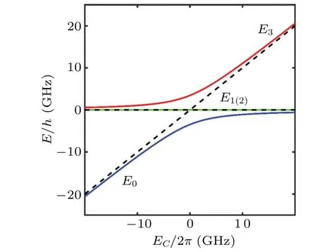
Fig.2.Energy level En (n=0,...,3) as a function of the center-dot detuning EC.The dashed line is the energy level without interdot tunnel coupling(t=0).Here,we calculate the energy levels with the parameters ε =0 and t/2π =2 GHz.
4.Coupling between a quadruple qubit and a resonator
The coupling between the QQD and a resonator is caused by the influence of the resonator electric field on the center dot chemical potentials and can be modeled as[20,34,37]
whereeis the electron charge,vpresents the conversion coefficient of resonator voltage applied to the center dot, and operatorVpresents the voltage on the resonator near the center dot.Since all resonator modes far detuned with the qubit are neglected,the coupling can be described as
Here,the annihilation operatoraand creation operatora†are for the relevant resonator mode with frequencyωr.g0=is the overall coupling strength,Zris the resonator characteristic impedance, andRQ=h/e2is the resistance quantum.According to recent experimental achievements using high-impedance resonator, the overall coupling strengthg0can be around 2π·100 MHz.[25,29,33]Furthermore,we write the interaction in the eigenbasis of the Hamiltonian shown in Eq.(1),
with the normalized photon coupling strength
Thus,we can obtain the photon coupling strength to the transition 0↔3 as
We note that the qubit does not have a dipole moment, since−e〈3|x|0〉 is equal to zero, wherexis the position operator.This indicates that the qubit can be protected from charge noise from the environment on the dipole axis.[34,35]As for the quadrupole moment, it can be determined as−2e2〈3|x2|0〉∝sinφ.Thus,we can consider that the quadruple coupling plays a leading role in the charge–photon interaction,and the dipole coupling is suppressed.
In Fig.3, we estimate the magnitude of the coupling,wheregq/g0is according to Eq.(15) and as a function of the center-dot detuningECand the interdot tunnel couplingt.WhenEC= 0, as illustrated by the red dashed line, the coupling strengthgqreaches its maximumg0.In the region where|EC| Fig.3.Calculated coupling strength as a function of EC and t.The red dashed line corresponds to EC =0, and the green dashed lines correspond to EC =±t. In gate-defined quantum dot systems, the qubit decay is caused by the charge–phonon coupling and should be of the order of a few MHz.[38–40]The dephasing is caused by the charge noise, which originates from random charge fluctuations of material or the control and confinement voltage giving rise to fluctuation energies.And the decoherence rate is given byγ=γr+γϕ,whereγris the decay rate andγϕis the dephasing rate. In this paper, we assume that all charge fluctuations satisfy Gaussian-distributed 1/fnoise with a power spectral densitySq(ω)=Aq|ω|−1, whereq∈{εC,ε}andAq=is the variance of noise power spectral density.The dephasing rate for the quadruple qubit can be approximated by the analytical expression[34,41] where we use the definitionsωp ≡ ∂ω3,0/∂pandωp,q≡∂2ω3,0/∂p∂qwithp,q∈{εC,ε}.For the case that the chemical potentials of the left, the upper, and the right dots are controlled by three independent plunger gates, we should consider about two additional detuning parameters in the dephasing processing,i.e.,p,q∈{εC,εL,εU,εR}. Fig.4.Dephasing rate γϕ as a function of εC and ε.We have chosen AεC/h2=1002 MHz2,Aε/h2=2002 MHz2,and t/2π =1.5 GHz. Figure 4 shows the calculated dephasing rateγϕas a function of the chemical potentials of the center dotεCand the detuning parameterε.The calculated result is symmetrical about the diagonal(εC=ε).And we can find that the dephasing rate reaches its minimum atεC=ε, where the dephasing rate caused by the charge noise in frist orderωApcan be negligible. After determining the system parameters of a QQD coupling to a resonator,let us describe the response of the hybrid system in teh resonator spectrum.Here,we assume a probing microwave transmitting through the resonator with frequencyωpand the resonator decay rateκ=κi+κ1+κ2consisting of the internal photon decay rateκiand the external photon decay rate through the input and output ports(κ1andκ2).Within a rotating-wave approximation, we can obtain the transmission by employing input–output theory,[23,32] Fig.5.(a) Resonator transmission spectrum |S21| as a function of EC and ωp.(b) The coupling strength gq and the qubit decoherence rate γ used in (a) as a function of EC.(c) Calculated vacuum Rabi splitting with (EC,t)/2π =(0,1.44) GHz (red dashed line), (EC,t)/2π =(1.22,1.40) GHz(black line),and(EC,t)/2π =(3.24,1.10) GHz(blue dashed line).In these calculations,we have chosen κ1=κ2=κ/2=2π·5 MHz, ωr/2π =5 GHz, and the overall coupling strength g0/2π =100 MHz.The parameters about qubit decoherence processing are γr =20 MHz,AεC/h2=1002 MHz2,and Aε/h2=2002 MHz2.The coherence parameters refer to Ref.[34]. In Fig.5(a), we show the calculated transmission as a function of the center-dot detuningECand the probe frequencyωp.Here, the amplitude of interdot tunnel couplingtis chosen ast=1.4 GHz<ωr/to ensure the observation of vacuum Rabi splitting in the resonator spectrum.The blue(red) dashed line represents the frequency of the uncoupled quadruple qubit(resonator).As the qubit is tuned close to the resonator, the avoided crossing caused by the charge–photon hybridization can be observed,i.e.,the original spectral line of the resonator will split into two spectral lines in the transmission spectrum.When the quadruple qubit is in resonance with the resonator at(the intersections of the blue and red dashed lines), the vacuum Rabi splitting of size 2gq/2πcan be observed.The green dashed line represents the transitions 0↔1 and 0↔2.Since these two transitions do not couple to the resonator,there is no corresponding avoided crossing in the resonator spectrum.If not, there must exist a difference among the chemical potentials of the left, the upper, and the right dot.Figure 5(b) shows the dependence of the coupling strengthgqand the qubit decoherence rateγon the center-dot detuningECin Fig.5(a).The coupling strengthgqreaches its maximum atEC=0,and the decoherence rateγreaches its minimum at the same position.This result is general and can be derived from Eqs.(15)and(16).Thus,we can fixECat zero to improve the quantum coherence performance of the quadruple qubit.Figure 5(c)shows the calculated vacuum Rabi splitting with differentEC.As|EC| increases, two spectral lines become blurred and their distance decreases with decreasinggqand increasingγ. According to the Eq.(15), the quadruple coupling strength can reach the overall coupling strengthg0whenEC=0.Thus,we can directly use the maximum charge-photon coupling strength max(gd)=g0.[20]in the system with a DQD coupling to a resonator to estimate the quadruple coupling strengthgq.For the decoherence processing, if we set the working position atEC=0, the decoherence rate can reach its minimum.Since the dephasing rate of the quadruple qubit mainly caused by the charge noise in the first order is suppressed and equal to zero,the decoherence rate of the quadruple qubit should be not higher than the decoherence rate of a DQD charge qubit on the sweet spot.[42]Thus, we can directly estimate the performance of the quadruple qubit from a charge DQD qubit.Referring to the parameters shown in recent experiments, Refs.[25,32,33], our approach can already be realized in the strong coupling regime(g>γ,κ)and used for system extension under the existing technical conditions. Also, the method mentioned in this work can be used in quantum dot systems with more connections in the center dot.For the case that the center dot coupling toNquantum dots,we can still encode the qubit in the lowest and the highest levels of the quantum dots system with frequencyand coupling strength. In this paper, we describe how to couple an electron shared among four quantum dots to photons stored in a resonator.The general method for obtaining the coupling strength and the decoherence rate of transitions of the electron in the QQD is systematically discussed.We choose the lowest and the highest levels of the QQD to encode the quadruple qubit, which can prevent the qubit from charge noise on the dipole axis and avoid other transitions.After determining the coupling strength and the decoherence rate, we find the optimal working point for charge–photon coupling and obtain the resonator spectrum of the hybrid system using the transmission coefficient given by the input–output theory.In short,our results show that the coupling mechanism is effective and realistic for coupling the quantum dot structure in plane to a resonator, since the qubit coherence time is improved while maintaining the coupling strength.Also, our work indicates a potential application in connecting two extension methods based on quantum dot networks and hybrid circuit QED architectures. Acknowledgement Project supported by the National Natural Science Foundation of China (Grant Nos.92265113, 12074368, and 12034018).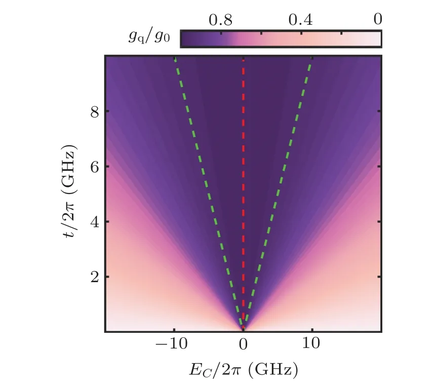
5.Decoherence rate of the quadruple qubit

6.Resonator spectrum

7.Discussion
8.Conclusion
- Chinese Physics B的其它文章
- Interaction solutions and localized waves to the(2+1)-dimensional Hirota–Satsuma–Ito equation with variable coefficient
- Soliton propagation for a coupled Schr¨odinger equation describing Rossby waves
- Angle robust transmitted plasmonic colors with different surroundings utilizing localized surface plasmon resonance
- Rapid stabilization of stochastic quantum systems in a unified framework
- An improved ISR-WV rumor propagation model based on multichannels with time delay and pulse vaccination
- Quantum homomorphic broadcast multi-signature based on homomorphic aggregation