
Runaway electron dynamics in Experimental Advanced Superconducting Tokamak helium plasmas
2023-09-05 08:48ChenXiLuo罗晨曦LongZeng曾龙XiangZhu朱翔TianTang唐天ZhiYongQiu仇志勇ShiYaoLin林士耀TaoZhang张涛HaiQingLiu刘海庆TongHuiShi石同辉BinZhang张斌RuiDing丁锐WeiGao高伟MinRuiWang王敏锐WeiGao高伟AngTi提昂HaiLinZhao赵海林TianFuZhou周天富JinPingQia
Chinese Physics B 2023年7期
Chen-Xi Luo(罗晨曦), Long Zeng(曾龙), Xiang Zhu(朱翔), Tian Tang(唐天), Zhi-Yong Qiu(仇志勇),Shi-Yao Lin(林士耀), Tao Zhang(张涛), Hai-Qing Liu(刘海庆), Tong-Hui Shi(石同辉), Bin Zhang(张斌),Rui Ding(丁锐), Wei Gao(高伟), Min-Rui Wang(王敏锐), Wei Gao(高伟), Ang Ti(提昂), Hai-Lin Zhao(赵海林),Tian-Fu Zhou(周天富), Jin-Ping Qian(钱金平), You-Wen Sun(孙有文), Bo Lv(吕波), Qing Zang(臧庆),Yin-Xian Jie(揭银先), Yun-Feng Liang(梁云峰),6, and Xiang Gao(高翔)
1Institute of Plasma Physics,Hefei Institutes of Physics Science,Chinese Academy of Sciences,Hefei 230031,China
2University of Science and Technology of China,Hefei 230031,China
3Department of Engineering Physics,Tsinghua University,Beijing 100084,China
4Advanced Energy Research Center,Shenzhen University,Shenzhen 518060,China
5Institute for Fusion Theory and Simulation,Zhejiang University,Hangzhou 310000,China
6Forschungszentrum Jülich GmbH,Institute of Energy and Climate Research Plasma Physics(IEK-4),Jülich 52425,Germany
Keywords: helium plasma,runaway electron,toroidal Alfv´en eigenmode(TAE),Experimental Advanced Superconducting Tokamak(EAST)
1.Introduction
The helium plasma operation is planned in the International Thermonuclear Experimental Reactor (ITER) during pre-fusion power operation, so the negative effect caused by the neutrons can be avoided.[1–3]Helium plasma disruption can potentially cause serious damage to the divertor and the first wall.Runaway electrons(REs)of several mega Amperes are expected to be generated during ITER deuterium and helium plasma disruption.Fruitful experiments have been done to address RE behaviors during both the flattop and disruption phases in deuterium plasmas.Note that the difference due to the effective charge number of the plasma (Zeff) between helium and deuterium plasmas can further contribute to distinction in plasma confinement,so it is essential to have an experimental understanding of RE behaviors in the helium plasmas.
The physics understanding of RE generation is that the driving force on electrons exceeds the collisional drag force from plasma particles, which results in electron acceleration.When the toroidal electric field exceeds the critical field[4–8]
electrons with momentum higher than the critical momentummvcwould enter the runaway regime.Here,neis the electron density and lnΛis the Coulomb logarithm.Several mechanisms can cause electrons to run away, including the Dreicer generation,[9,10]hot tail RE generation,[11–14]RE avalanching,[15]tritium decay,[16]radio-frequency wave heating[15,17]and Compton scattering ofγ-rays from the activated wall.During the flattop, the Dreicer generation is the dominant primary RE mechanism and creates adequate RE seed population which is further amplified by the secondary RE generation named avalanche mechanism.
On the other hand,there are some limits on the maximum energy the REs can reach, which are set by, amongst others,bremsstrahlung radiation,[15,16]synchrotron radiation,[18]drift orbits,[19]magnetic field ripples[20]loop voltage and magnetic turbulence.[21,22]These phenomena can limit the energy of REs, remove the REs from the confined plasma and damp the RE current.Especially,observation of whistler waves,[23]Alfv´en eigenmodes(AEs)[24]and other kinetic instabilities in the MHz range[25]driven by REs can account for anomalous RE dissipation, suggesting that kinetic instabilities could be considered to be one possible way to cause the controllable RE losses.
In this paper, we observe RE behavior in helium plasma during low density ohmic discharge in EAST and analyze its some characteristics.This paper is organized as follows.Section 2 introduces the basic settings and observed results of concerned experiment represented by the typical discharge of shot 87059.Section 3 describes the performance of RE production in helium plasma,and explains the reason why there are more REs in helium plasma.In Section 4, we presents the Alfv´en eigenmodes driven by the RE in helium plasma and discusses the causes for the difference between the mode frequency and the statistical consequences.The conclusion of this paper is given in Section 5.
2.Experimental setup
The experiment is performed with non-circular cross section in low-density helium ohmic plasmas in Experimental Advanced Superconducting Tokamak (EAST) which is a full superconducting tokamak device.Crucial parameters are presented as follows: major radiusR= 1.85 m, minor radiusa=0.45 m, toroidal magnetic fieldBt=2.5 T, the plasma currentIp=400 kA–500 kA,the line-averaged electron densities in the range of 0.5×10¹⁹m−3–3.0×10¹⁹m−3, and the helium concentration in the range of 30%–80%.The electron temperature (Te) is measured by multi-channel electron cyclotron emission (ECE) and Thomson scattering (TS)[26]system.Besides, hard x-ray(HXR)and ECE diagnostics can measure the radiation, and to some extent can be applied to represent the quantity of REs because of distinguished mechanisms.The ECE measures superthermal cyclotron radiation and HXRs are correlated with bremsstrahlung radiation,which refers to any radiation due to slowing of electrons.Because the CdTe detector possesses higher stopping power,[27]as a result,HXR can measure REs in higher energy bands,specifically in the range of 30 keV–300 keV.[27,28]Figure 1 presents the detailed toroidal locations of the essential diagnostics and poloidal view of HXR in EAST.Furthermore, the directions of plasma current and toroidal magnetic field are also noted.
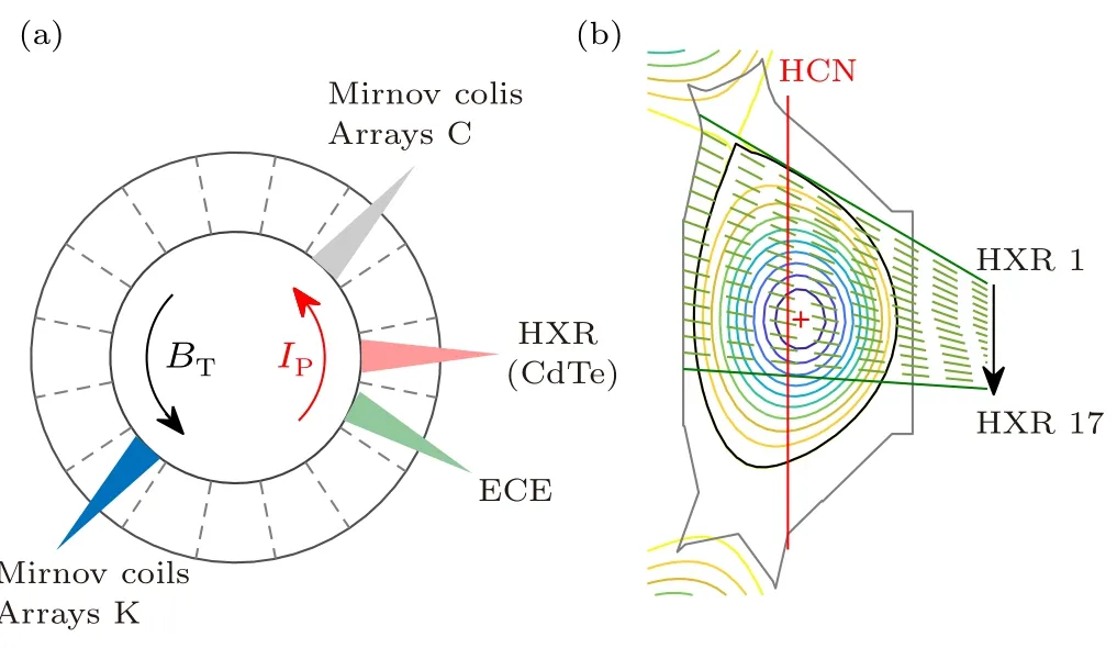
Fig.1.(a)Toroidal views of essential diagnostics ECE,HXR and Mirnov coils.The directions of the plasma current and toroidal magnetic field are also presented.(b)View of poloidal HXR system and the location of HCN interferometer.

Fig.2.Time trace of helium plasma in shot 87059 and 86831 showing(a)and(d)ratio of toroidal field to critical field and plasma current Ip,(b)and(e)plasma line-averaged density ne and loop voltage Uloop,(c)and(f)HXR for CdTe and ECE signal.
Figure 2 presents two typical helium ohmic plasmas in which both of them are accomplished with the divertor configuration,however,with different electron density evolution.One discharge with the electron density ramp-down is set to characterize RE onset and the other with the constant electron density during the current platform is used to obtain RE growth rate.In both discharges, the electron density reaches maximum at∼2.5 s during current flattop.As shown in Figs.2(c)and 2(f),the strong hard x-rays(HXR)are detected and indicate that RE has been produced in the current ramp-up phase of the discharges.The ratio of toroidal field to critical field[29]is
which reaches up to 15 during current ramp-up, and subsequently decreases to 3 during the density ramp-up phase.The value is larger than the threshold electric field for RE generation in the range of 6–11 in EAST deuterium plasmas,[29]so an initial RE population is created by the electric field during the current ramp-up phase and then dissipated due to increased collisionality.
In the first case,the line-averaged density is controlled to decrease from 2×10¹⁹m−3to 0.4×10¹⁹m−3in Fig.2(a),which is used to characterize the RE onset.HXR gradually rises to the peak and then decays at the beginning of the density ramp-down phase.Meanwhile,Eloop/Ecand ECE increase when theEloop/Ecexceeds a threshold value, HXR reaches a turning point and dose not continue to decay while density continues decreasing.The turning point is considered to represent the appearance of threshold field and RE onset.Differently, in the other case, Fig.2(d) shows the discharge with a constant density during the current platform.Unlike the scenario with density ramp-down,Eloop/Eckeeps a constant and HXR decreases during the density platform phase,which could provide a method to evaluate the dependence of the HXR growth rate on plasma density.
3.RE generation in helium plasma
The quiescent operation regime with generation of a large number of REs has been achieved in helium plasma.The basic experimental conditions including plasma current,toroidal magnetic field and configuration are fixed in helium and deuterium plasma.However, inherent properties of helium and deuterium plasma present certain discrepancies,which would further lead to different RE behaviors.Take shots 87059 and 90950 for examples, and Fig.3 presents the comparison of key parameters relate to REs with the similar density evolution.The concentration of helium gradually increases due to the helium gas injected during current ramp-up phase,and then the gas puffing is turned off with the concentration of helium reaching 65%.With no more helium injected, recycling of stagnated deuterium on the device wall in flat-top phase further declines the concentration of helium.The amplitudes of ECE and HXR signals are both higher in helium plasma, revealing that the yield of REs in helium plasma is higher than that of deuterium plasma at the same density.Actually, the homologous result has been observed during the whole discharge.

Fig.3.Comparison of typical plasma parameters in helium and deuterium plasma.The moments of ne =1.9×10¹⁹ m−3 of helium and deuterium plasmas are labeled by grey dotted line.
The HXR amplitude and its corresponding growth rate in helium and deuterium plasma have been compared in Fig.4.It illustrates that in the same electron density,both of the two values are higher in helium plasma.Moreover, two criteria have been used to find out the threshold density for RE generation, (i) the HXR signals transit from decay to growth and (ii) the growth rate of HXR signals becomes lager than 0, respectively.The onset electron density for RE primary generation is∼0.9×10¹⁹m−3in helium plasmas, which is∼0.6×10¹⁹m−3in deuterium plasmas,indicated in Fig.4.
As shown in Fig.4(b), the growth rate of HXR signals is clearly lower in deuterium plasmas.Furthermore,Fig.5(a)statistically presents the RE growth rate of helium plasma is generally higher than that of deuterium in a large range of electron density platform, suggesting that helium plasma is more favorable for RE generation than deuterium plasma.Besides,the detected RE growth rate linearly decreases with increasing density,which can be interpreted as that with higher background plasma density,the effective cross-section of collision between REs and the bulk plasma increases.Larger collisional cross-section will subsequently lead to more collisional loss,and eventually, the production of REs is partly suppressed.Figure 5(b) shows the threshold electric fieldEthfor Dreicer mechanism in helium plasma and deuterium plasma at the different plasma current platform.A largerEth/Ecof deuterium plasma than helium plasma is found in the same current platform,and further proves that the helium plasma can trigger the Dreicer mechanism more efficiently.[29]

Fig.4.Comparison of (a) HXR amplitude and (b) HXR growth rate between helium plasma and deuterium plasma.The grey dotted line in panel(b)represents the value at which the HXR growth rate is 0.
A certain moment at which the helium plasma and deuterium plasma possess the same electron density is selected to perform the spatial distribution and amplitude of HXR signals as shown in Fig.6.The maximum value appears in the 13-channel measurement due to the integrated line passing through the core plasma.The HXR intensity is also affected byZeff,as bremsstrahlung is not only produced by REs hitting on the wall of vacuum chamber,but also part of it is constituted by bombardment of the collision between the REs and ions inside the plasma.Moreover, HXR intensity from electron–ion collision is proportional toZeff.As a result,the HXR intensity in deuterium is multiplied by the ratio ofZeffof helium and deuterium plasma to exclude the concern that helium plasma HXR can process higher HXR amplitude caused by higherZeff.Figure 6 reveals that the HXR amplitude in the helium plasma is always higher when the density is lower than the threshold density for RE generation.This result confirms that the helium plasma is conducive to the generation of RE as a whole.
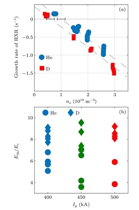
Fig.5.(a) HXR growth rate as a function of electron density.(b) The threshold electric field for Dreicer mechanism for helium and deuterium plasma in different plasma current Ip.

Fig.6.Spatial distribution of HXR at the same electron density.
Whether the electron can run away to a certain extent depends on if the accelerating electric field exceeds the critical electric field.Since theEcis inversely proportional to the electron velocity of which the distribution function is closely correlated with temperature, the dependence of the critical electric field on velocity can be simply referred to electron temperature.Therefore, the number of the electrons exceeding the runaway threshold is likewise related toTe.Several factors can lead to the difference of RE quantity produced in helium and deuterium.Atomic properties of helium are much different from deuterium, which may contribute to significant distinction on density or temperature profiles.[30]Helium plasma discharges with a similar density distribution are detected with a bit higher electron temperature as shown in Fig.7.The electron temperature in helium plasma measured by Thomson scattering is higher than that in deuterium plasma and the temperature gap between helium and deuterium reaches up to a few hundred eV, which is consistent with the results checked by ECE diagnostic.The peak in the core may be due to the uncertainty of diagnostic systems and the contribution of REs to ECE signals.

Fig.7.(a)Temperature distribution of helium and deuterium plasma along normalized radii measured by Thomson scattering and ECE.(b) The density distribution of helium plasma and deuterium plasma along normalized radii measured by microwave reflectometry.
To further analysis the evolution of REs,a 0-D model,including primary generation and secondary process, has been applied with measured time-traces of plasma parameters.The RE model is proposed in Refs.[7,31,32], with a plain settlement of RE generation issue
The first term on the right-hand side in the Eq.(3)referring to primary generation is given by
whereε{D,C} ≡Eloop/E{D,C}is the normalized electric field,Zeff=∑i ni/∑i niZi[33]is the effective charge number of the plasma, lnΛis the coulomb logarithm which depends on the density and temperature,νee=nee4lnΛ/(4π) is the collision frequency,is the electron thermal velocity,andk=0.21+0.11[30]is an order unity correction.RE losses term is simply characterized by the confinement timeτRE.Note that only primary mechanism is in the scope of this study at the RE onset.
According to Eq.(4), there is an inherent temperature dependence in the primary RE generation growth rate for a set value ofEloop/Ec.[32]Numerically,this can be understood from the RE primary growth rate
The RE growth rate is exhibited as a function of theEloop/Ec,Zeffand temperature,as shown in Fig.8,in which the plasma parameterne= 2×10¹⁹m−3is applied in Eq.(5) and the color bar represents the logarithmic value of the RE growth rate.Figure 8(a) distinctly reveals that, for the case with the fixed value ofEloop/Ec,the RE growth rate of helium is higher than deuterium.For all regions withEloop/Ecless than 1.5 and electron temperature≤2.5 keV, the corresponding logarithmic value of RE growth rate is less than 10−20, which indicates that substantially no REs can be generated in the range ofne≤1020m−3.The white solid lines are delegating the corresponding value ofEloop/EDand suggests thatEloop/EDshould be at least larger than 0.02 to create a ponderable runaway formation to occur.[34]Despite that Eq.(5)predicts that lowerZeffof deuterium does favor to produce RE population,helium plasma is more favorable to RE generation as shown in Fig.8(b), which demonstrates the RE growth rate is less insensitive toZeffcompared with electron temperature.The generation rate of RE is positively correlated with theTe, as a result, the magnitude and production rate of RE in helium plasma precede them in deuterium plasma.Figure 8 also reveals that two conditions, including the electric field strength larger than the critical electric field and the value ofEloop/EDbeyond the range of 0.01–0.02,need to be satisfied for the significant RE production.Besides,in the case of the same density, more background electrons in helium plasma can access the runaway area and provide more RE seeds for the avalanche process.
With comparing RE behaviors in deuterium and helium plasma,it is realized that the growth rate of hard x-rays is negatively correlated with electron density, and the growth rate of HXR of helium plasma is higher than that of deuterium plasma.This indicates that under the same discharge parameters, helium plasma will produce more REs due to the higher temperature.Considering the presence of multiple diagnostic signals,more REs are confirmed to be generated in the helium plasma,which further indicates that the effect ofZeffon HXR is not as sensitive as electron temperature here.The critical electric field has a strong dependence on electron temperature as derived from the source term of the RE.At the same time,the corresponding electron density when the HXR growth rate equals zero is consistent with the experimental value within the error tolerance range.

Fig.8.The RE growth as a function of (a) electron temperature and Eloop/Ec,(b)effective charge number of the plasma and electron temperature.White solid lines refer to Eloop/ED.
4.AEs driven by energetic electrons in helium plasma
The kinetic instability mainly changes momentum distribution of fast particles and the instabilities appear in various discharges processes in the form of relaxation oscillations.[25,35]The excitation of these instabilities such as shear Alfv´en wave(SAW)instabilities,may lead to scattering of REs,and thus,a plausible mitigation of the damage caused by the rapid loss of REs to the wall.Excitation of SAW instabilities by REs has been observed in EAST deuterium plasmas with the quiescent operation regime.Here, we present SAW instabilities driven by REs in EAST helium plasmas.Since helium has a different runaway behavior from deuterium,it may cause differences in the manifestations of these instabilities.
Figure 9 shows the spectrum of magnetic fluctuation and typical plasma parameters related to the runaway discharge.Several modes have been observed from Mirnov coil during the density ramp-down phase in helium plasma.There are two distinct fluctuations with different frequencies in shot 87475,as shown in Fig.9(c).The high-frequency mode appears prior to the low-frequency mode, and their frequency evolutions are significantly different.Similar modes have been observed in deuterium plasmas,which are identified as Alfv´enic modes.[36]However, the frequency evolution of the modes in helium plasma does not fully satisfied with the Alfv´en scaling,and when the extension of Alfv´en frequency is towards 0,the high frequency branch is∼50 kHz rather than 0 kHz like modes in deuterium do.These discrepancies will be addressed latter.In addition, the toroidal mode number of each mode is determined by the phase difference of the toroidal magnetic pickup coil array,the toroidal mode numbers of the two modes are both 1 but their poloidal mode numbers are not the same.

Fig.9.(a)Time traces of electron density and loop voltage.(b)Evolution of HXR signal.(c)Spectrum of magnetic pick-up coils.(d)Spectrum by the microwave reflectometry of 91.8 GHz.
The SAW dispersion relation can be expressed as[37]
wherek‖≃(nq −m)/(qR) is the wave vector along the magnetic field and is affected by the equilibrium magnetic geometry,and
is the Alfv´en speed in the helium plasma.Here,µ0=4π×10−7N·A−2is the vacuum magnetic permeability, andρmis the mass density.As the SAW propagates along the equilibrium magnetic field of a torus, the velocity is periodically modulated,and form Alfv´en eigenmodes(standing waves)as the Bragg condition is satisfied.Figure 10(a)extracts the measured toroidal Alfv´en eigenmode (TAE) frequency and compares them with the theoretical TAE frequency, in whichmiis set as 3×1.67×10−27kg and other experimental conditions are similar.The calculated mode frequency cannot extend to 0 when Alfv´en frequency equals to 0,which is different from the performance in deuterium plasma and does not agree with the theoretical prediction.Normally,the calculated results of Alfv´en frequency are not affected by the mass modification.Under ordinary circumstance, the mass density is theoretically independent ofZeffand the relative concentration of helium-to-deuterium when fully stripped.[38]However,for a quasi-neutral and low plasma temperature with higherZeff,especially the electron density and electron temperature are low near the edge of plasma, so the mass modification should be taken into account for the helium plasma with not full-stripped helium ions in the calculation.It is found that for the certain discharge condition from the Eq.(7),vAmainly depends on the plasma density and mass.The helium plasma share evolution is shown in Fig.11(a)and the plasma mass is given by
whereHe/(He+D) is the concentration of helium in the plasma,which is defined by the ratio of helium density to main ion densityfHe=nHe/(nHe+nD).In the helium plasma,there will be a considerable amount of deuterium from wall recycling during the discharge process.As a result, the particle proportion of helium plasma need to be considered when calculatingvA.The plasma electron density decreases after terminating the helium gas puffing which subsequently leads to the proportion decrease of helium plasma,as shown in the shadow area in Fig.11(b).As a result,the concentration is not fixed at a certain value but gradually decreases as time progresses,so does the resultant plasma mass.Moreover, the overall value of mass density is gradually higher than the previous value.Figure 10(b) indicates that with the updated mass value been substituted into Eq.(8),the high-frequency branch can be reversely extended to a value of 0 and the fit well with theory in discharge 87475.However, the low-frequency branch still cannot achieve similarly,which could be further explained by effects of different electron density.

Fig.10.(a)Linear comparison between experimental mode frequency and theoretical Alfv´en frequency.(b)Theoretical Alfv´en frequency and actual mode frequency obtained by mass correction.(c)Comparison of mode frequency with/without density modification.
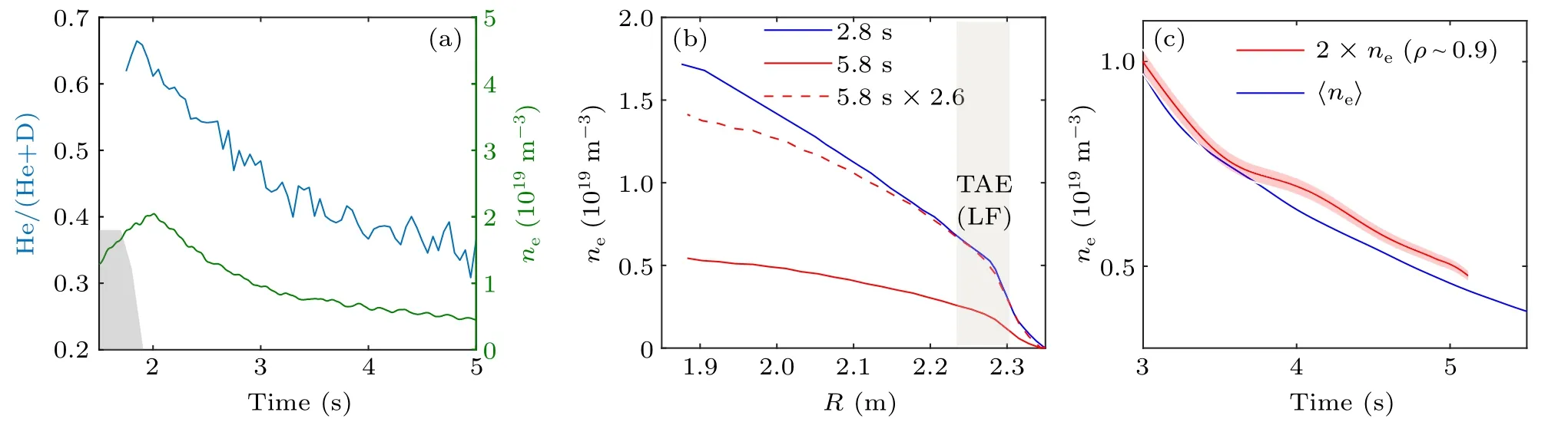
Fig.11.(a)The ratio between helium plasma and deuterium plasma with gas puffing,and time trace of electron density.(b)The density measured by the microwave reflectometry.(c)Comparison between line-averaged density and density measured by microwave reflectometry at ρ ∼0.9.
The difference in density may be due to different locations of the two modes.The cross-power spectrum shown in Fig.12 indicates that a significant distinguished phase difference exists between the high-frequency branch and lowfrequency branch.The toroidal mode numbers of the two modes are both identicallyn=1, which eventually indicates that the poloidal mode is not the same and the two modes are different in the radial position.The mode position measured by microwave reflectometer is exhibited in Fig.9(d).The low-frequency branch mode of TAE can be seen clearly when the incident frequency of the microwave reflectometer is 91.8 GHz,which proves that the low-frequency branch is relatively closer to plasma boundary.The low-frequency branch can only be observed after 3.4 s at the detection frequency of 91.8 GHz, which is due to the fact that the detective position is moving along the radial direction as electron density decreases.As we addressed, electron density measured by the HCN diagnostic is line-averaged density and is inconsistent with the density of two modes with different spatial distribution.
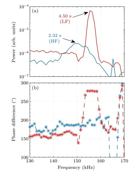
Fig.12.(a) Cross-power spectrum of the strength and (b) the poloidal phase difference of low-frequency branch (red solid line) and highfrequency branch(blue solid line).
To illustrate the discrepancy clearly between density profiles at 5.8 s and 2.8 s measured by microwave reflectometry,the profile at 5.8 s has been multiplied by a factor of 2.6, as shown in Fig.11(b).The plasma density in the core at 2.8 s is significantly higher than that at 5.8 s,which is probably due to the weaker inward pinch of particles in such low-density discharge.The approximate radial position of the low-frequency branch based on reflectometry has been noted in Fig.11(b)betweenρ ∼0.85 andρ ∼0.95,in which the plasma density is more proper to modify the calculated Alfv´en frequency of low-frequency mode rather than line-average density we used before.The updated results are exhibited in Fig.10(c),density applied in this calculation is roughly fromρ ∼0.9.For the low frequency branch with this density modification, the theoretical frequency is identical zero when the experimentally observed mode frequency is 0, which also demonstrates the rationality of density correction.
Due to the limitation of experimental diagnostics, it is difficult to obtain the accurate poloidal number and the specific type corresponding to each mode, thus, the position of the mode frequency in the continuum is further applied to distinguish the mode.The TAE gap of the reconstituted AE continuum is in accordance with the measured magnetic fluctuation of helium plasma discharge 87475, in which the EFIT code provides the essential equilibrium and microwave reflectometry is further applied together to obtain the density profile.With the combination of previous numerical calculation and experimental observation, the general locations of these modes are exhibited as red dotted line in Fig.13,in which the low-frequency branch lays in TAE gap and should be identified as TAE.Based on the comprehensive frequency information,one part of the high-frequency branch lays in the TAE gap and another part is located at the bottom of the ellipticity induced Alfv´en eigenmodes (EAE) frequency gap across the continuum.When the toroidal effect is dominant, the coupling impression of the shear Alfv´en wave and energetic particles will cause the nonlinear saturation of the TAE,whereas,the highfrequency branch can also be a nonlinearly EPs driven EAE when the elongation effect is dominant.

Fig.13.Alfv´en continuum in discharge 87475 at t=2.8 s by the general Alfv´en mode solver eigenvalue code.The green dashed line presents the electron density profile.The red dotted line indicates the possible range of the experimentally observed mode frequency.
5.Conclusion
Quiescent operation regime with generation of a large number of runaway electrons (REs) has been achieved in helium ohmic plasmas on EAST.The energetic electrons,namely REs,are obtained by controlling the decrease of electron density in the flat top section of the current.The onset electron density for RE generation is∼0.9×10¹⁹m−3in helium plasma,which is higher in deuterium plasma.HXR and ECE signals are further indicate that more REs are produced in helium plasma than in deuterium plasma.The growth rate of HXR in helium plasma is clearly higher than in deuterium plasma with a constant electron density, which indicates that RE can be more easily dissipated due to collision in deuterium plasma.Besides, RE growth rate according to HXR signals both in helium and deuterium plasma is inversely proportional to electron density.Simulation results show that RE formation exhibits extremely strong dependence on electron temperature and is enhanced at higher temperature.The electron temperature in helium plasma is confirmed higher than deuterium plasma, supporting the calculated results.Further, the RE growth rate is less sensitive toZeffcompared with electron temperature.
High frequency AE (100 kHz–300 kHz) instabilities excited by REs in the helium plasma have been observed.Two AEs are observed with toroidal mode numbern= 1 and the poloidal mode is different.The microwave reflectometer(91.8 GHz)indicates that the low frequency branch locates atρ ∼0.9,and the radial position of high frequency branch is relatively closer to the core.The frequency evolution shows that when the Alfv´en frequency touches to 0, the high-frequency branch cannot close to the 0.With the modifications of mass density and localized density, calculated mode frequency can touch 0 and consist well with theory results.Besides, the low frequency branch evolution results show that its frequency∼50 kHz when the theoretical Alfv´en frequency is 0, which is inconsistent with the deuterium plasma.Based on the microwave reflectometry signal analysis, the density difference between the plasma boundary and core may contribute to this discrepancy.
The higher rate of RE production in helium plasma will affect a series of instabilities related to REs that occur inside the fusion device.These instabilities such as SAW excited by REs will result in the scattering of REs and further abnormal transport.These effects are considered as possible mechanism to mitigate the damage caused by the rapid loss of REs to the wall.The helium plasma discharge pattern is adopted in the ITER,and the study of the plasma RE phenomenon will provide a basis for the stable operation of ITER.
Acknowledgments
Project supported by the National Key R&D Program of China (Grant Nos.2017YFE0301205 and 2022YFE03050003),the Youth Innovation Promotion Association of Chinese Academy of Sciences(Grant No.Y2021116),the National Natural Science Foundation of China (Grant Nos.12005262, 12105186, 12175277, and 11975271), and the Users of Excellence Program of Hefei Science Center CAS(Grant No.2021HSC-UE016).
猜你喜欢
Chinese Physics B(2023年1期)2023-02-20
金秋(2022年10期)2022-11-25
Chinese Physics B(2022年2期)2022-02-24
江苏教育(2021年59期)2021-12-02
Chinese Physics B(2021年2期)2021-03-11
Chinese Physics B(2021年1期)2021-01-21
理论与创新(2020年1期)2020-04-20
金山(2020年3期)2020-04-15
Chinese Physics B(2019年8期)2019-08-16
Chinese Physics B(2019年6期)2019-06-18

- Chinese Physics B的其它文章
- Interaction solutions and localized waves to the(2+1)-dimensional Hirota–Satsuma–Ito equation with variable coefficient
- Soliton propagation for a coupled Schr¨odinger equation describing Rossby waves
- Angle robust transmitted plasmonic colors with different surroundings utilizing localized surface plasmon resonance
- Rapid stabilization of stochastic quantum systems in a unified framework
- An improved ISR-WV rumor propagation model based on multichannels with time delay and pulse vaccination
- Quantum homomorphic broadcast multi-signature based on homomorphic aggregation