
Design of a photonic crystal fiber polarization beam splitter with simple structure and ultra-wide bandwidth
2023-11-02 08:10YunPengWei魏云鹏JinHuiYuan苑金辉YuWeiQu屈玉玮ShiQiu邱石XianZhou周娴BinBinYan颜玢玢KuiRuWang王葵如XinZhuSang桑新柱andChongXiuYu余重秀
Chinese Physics B 2023年10期
Yun-Peng Wei(魏云鹏), Jin-Hui Yuan(苑金辉),,†, Yu-Wei Qu(屈玉玮),Shi Qiu(邱石), Xian Zhou(周娴), Bin-Bin Yan(颜玢玢),Kui-Ru Wang(王葵如), Xin-Zhu Sang(桑新柱), and Chong-Xiu Yu(余重秀)
1State Key Laboratory of Information Photonics and Optical Communications,Beijing University of Posts and Telecommunications,Beijing 100876,China
2Research Center for Convergence Networks and Ubiquitous Services,University of Science&Technology Beijing(USTB),Beijing 100083,China
Keywords: dual-core photonic crystal fiber,polarization beam splitter,extinction ratio,bandwidth
1.Introduction
Polarization beam splitter (PBS), as one of the essential components, can be used as the polarization division multiplexer, optical filter, optical splitter,etc.in optical communication and sensing systems.[1-5]It is mainly used to separate the light beams in the orthogonal polarization directions.[6-9]Over the past two decades, photonic crystal fiber (PCFs)have received great attention due to their unique optical characteristics.[10-14]In recent years, some researches have concentrated on the PBSs based on the dual-core PCFs (DCPCFs).[15,16]In 2019,Chuet al.designed a DC-PCF PBS fabricated with Ge20Sb15Se65glass,where the splitting length of 63 µm and working bandwidth of 80 nm are achieved.[17]In 2021, Zhanget al.proposed a DC-PCF PBS based on Ge10As22Se68glass, and their simulation results showed that the working bandwidth and splitting length are 60 nm and 636µm,respectively.[18]In the same year,Renet al.demonstrated a silica DC-PCF PBS, with the working bandwidth of 48 nm and the splitting length of 254 µm.[19]In 2022,Zhang investigated a compact gallium sulfide DC-PCF PBS,whose working bandwidth is 170 nm and splitting length is 277.1µm.[20]
Generally speaking, the performances of the DC-PCF PBS can be improved by selectively filling different functional materials (such as gold, silver, and liquid crystal) into the cladding air holes.[21]In 2021, Zhanget al.designed a gold wire-filled DC-PCF PBS with the three kinds of air holes,where the working bandwidth is 120 nm and the splitting length is 249.12 µm.[22]In 2022, Quet al.proposed a gold wire-filled X-shaped DC-PCF PBS based on the Ge20Sb15Se65glass, where the working bandwidth is 358 nm and the splitting length is 230 µm.[23]However, it brings new challenges to the preparation to fill the functional materials into the air holes.[24]
Proposed in this work is a DC-PCF PBS with simple structure and ultra-wide bandwidth.With the full-vector finite element method(FV-FEM),the influences of the structure parameters of the DC-PCF PBS on the coupling length (CL)and coupling length ratio(CLR)are investigated.The simulation results show that the proposed DC-PCF PBS has a large bandwidth of 340 nm,covering the S+C+L+U communication bands,a splitting length of 1.97 mm,and an extinction ratio(ER)of 59.08 dB at wavelength 1.55µm.
2.Design of DC-PCF PBS and theory
Figure 1 shows the cross-sectional structure of the proposed DC-PCF PBS.The simple structure contains the rectangular and hexagonal lattices and three kinds of air holes in the cladding region.The asymmetrical elliptic cores A and B are formed by separately removing the two air holes in theXdirection orYdirection.The ten largest air holes with the diameterd1lie in theYdirection of the core A and±45°angle direction of the core B,five larger air holes with the diameterd2lie in theXdirection of the core A andYdirection of the core B,and other air holes with the diameterd3are distributed in the outer region of the cladding.The hole-to-hole pitch of the rectangular lattices isΛ, so the hole-to-hole pitch of theYdirection and the diagonal direction in the hexagonal lattice areΛandseparately.In the simulation, the complete grid contains 57630 domain elements,and the grid size of the perfectly matched layer(PML),silica,and air holes are all set toλ/6.The scattering boundary condition is set at the edge of the structure, and the PML is set at the periphery of the structure.The thickness of the PML isΛ,and its refractive index is set to 0.03,which is higher than the silica material’s.[25]The PML and scattering boundary condition can ensure that no reflection occurs at the boundary when the light beam enters the outer space.The thickness of the PML can affect the calculation accuracy and time.[25]

Fig.1.Cross-sectional structure of the proposed DC-PCF PBS.
We use the following dispersion equation to describe the refractive index of silica[26]
whereA1= 0.6961663,A2= 0.4079426,A3= 0.8974794,B1= 0.0684043 µm2,B2= 0.1162414 µm2, andB3=9.896161µm2.The related coefficients are determined by the specific material(fused silica)and temperature(25°C).[27]
According to the dual-core coupled mode theory, there should exist four supermodes when the incident light enters one of the cores A and B.That is, theX-polarized (X-pol)odd mode,X-pol even mode,Y-polarized (Y-pol) odd mode,andY-pol even mode.Because of the difference in propagation constant between theX-pol andY-pol odd and even modes,the light energy will transfer periodically between the two cores.[28]To describe the propagation and coupling characteristics of theX-pol light andY-pol light in the proposed DC-PCF PBS,the coupling length(CL)of each polarized light can be calculated from the following formula[29]

According to the working principle,when the mixed polarized light enters the core A or core B,it will be completely split into theX-pol light andY-pol light at a specific splitting length.[31]In the following,the normalized output power(NOP) is used to describe the transfer of the light energy between the core A and the core B at different propagation distances:[32]
whereLP,Pin,andPoutrepresent the splitting length,the incident light power, the output light powers from the two cores,respectively.According to Eqs.(4) and (5), the variation of the NOP with splitting length at a specific wavelength can be obtained, and the variation of the NOP with wavelength at a specific splitting length can also be obtained.The extinction ratio(ER)is defined as[33]
where the ER can directly evaluate the performance of the proposed DC-PCF PBS.When the ER value is larger than±20 dB,the power of one polarized light is 100 times higher than the other one and it is enough to separate two orthogonal polarization light beams.[34]Therefore, the wavelength range in which the ER is greater than±20 dB can be considered as the working bandwidth of the DC-PCF PBS.[35]
We also calculate the insertion loss of the DC-PCF PBS.[36]The insertion loss ILX,Ycan be expressed as[37]
3.Simulation results and discussion
The initial structure parameters of the proposed DC-PCF PBS are chosen as follows:d1= 2.0 µm,d2= 1.6 µm,d3=1.5µm,andΛ=3.2µm.With the FV-FEM,the effective refractive indices of the four supermodes in the wavelength range from 1.3 µm to 1.8 µm are shown in Fig.2.Figure 2 shows that the effective refractive indices of the four supermodes drop gradually as wavelength increases, and those of theX-pol andY-pol even modes are always higher than those of theX-pol andY-pol odd modes.Besides, as wavelength increases, the difference between the effective refractive indices becomes larger.The mode field distributions calculated at wavelength 1.55 µm are shown in Figs.3(a)-3(d).It can be seen from Figs.3(a)-3(d)that the mode field energy can be well confined in the cores A and B.
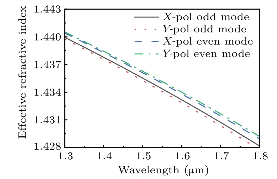
Fig.2.Effective refractive indices of X-pol odd mode, X-pol even mode,Y-pol odd mode,and Y-pol even mode of the proposed DC-PCF PBS in considered wavelength range from 1.3µm to 1.8µm.

Fig.3.Mode field distribution of (a) X-pol odd mode, (b)Y-pol odd mode, (c)X-pol even mode, and(d)Y-pol even mode of the proposed DC-PCF PBS calculated at wavelength 1.55µm,with red arrows representing the directions of electric fields in cores A and B.
Figure 4 shows CLX,Yand CLR of the proposed DC-PCF PBS.Figure 4 demonstrates the decreasing trends of the CLX,Yand the increasing trend of the CLR,which are consistent with the results obtained from Eqs.(2) and (3).The trend that CLX,Ydecreases and CLR increases is attributed to the fact that the difference in effective refractive index between theXpol andY-pol odd and even modes increase faster as wavelength increases.The CLXand CLYcalculated at wavelength 1.3 µm are 1.42 mm and 0.86 mm, respectively, and the corresponding CLR is 1.65.With the increase of wavelength,the CLR at wavelength 1.55µm is calculated to be 1.79.
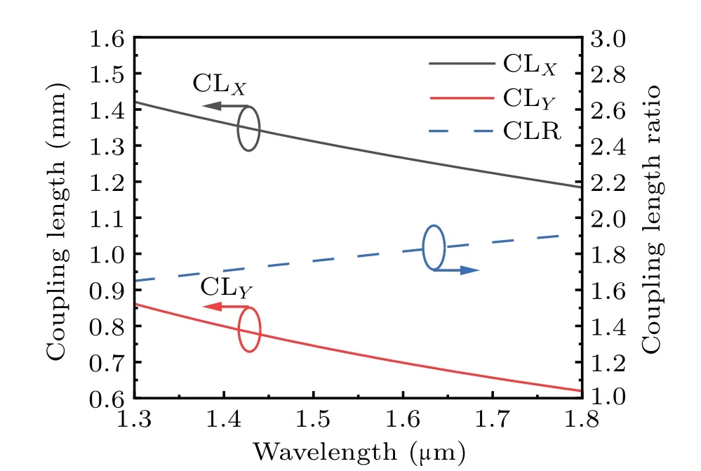
Fig.4.Variation of CLX,CLY,and CLR of the proposed DC-PCF PBS with wavelength.
In the following, the effects of the structure parameters(d1,d2,d3,andΛ)of the proposed DC-PCF PBS on the CLX,CLY,and CLR will be analyzed in the considered wavelength range from 1.3µm to 1.8µm.Figures 5(a)-5(c)show the calculated CLX,CLY,and CLR as functions of wavelength whend1changes from 1.8 µm, to 1.9 µm, to 2.0 µm, to 2.1 µm,and to 2.2 µm, respectively.From Figs.5(a) and 5(b), for different values ofd1, the CLXand CLYcurves show the decreasing trends as wavelength increases,and the CLXvalue is larger than the CLYvalue at the samed1.Moreover, at the determined wavelength,the CLXand CLYvalues decrease asd1increases.From Fig.5(c), the CLR value increases gradually with the increase of wavelength, and decreases withd1increasing.

Fig.5.Effects of d1 on(a)CLX,(b)CLY,and(c)CLR of the proposed DC-PCF PBS.
Whend2changes from 1.4 µm, to 1.5 µm, to 1.6 µm,to 1.7 µm, and to 1.8 µm, respectively, the calculated variations of CLX, CLY, and CLR with wavelength are shown in Figs.6(a)-6(c).From Figs.6(a)and 6(b),for different values ofd2,the CLXand CLYgradually decrease as wavelength increases,and the CLXvalue is larger than the CLYvalue under the samed2.At the determined wavelength,the CLXand CLYvalues increase asd2increases.In addition,unlike the scenario of CLX,the change of the CLYcurve on the shorter wavelength side is more sensitive than that at the longer wavelength side.From Fig.6(c), the CLR curves show the increasing trends as wavelength increases,and the CLR value increases withd2increasing.
Figures 7(a)-7(c) show the calculated CLX, CLY, and CLR ford3changing from 1.3 µm, to 1.4 µm, to 1.5 µm, to 1.6µm,and to 1.7µm,respectively.From Figs.7(a)and 7(b),for different values ofd3,the CLXvalue decreases steadily as wavelength increases,and the change of the CLYvalue shows the similar trend to that of the CLX.Moreover, the CLXand CLYvalues slightly increase with the increase ofd3at the determined wavelength.However, comparing withd1andd2,the change ofd3has the smallest effect on the CLXand CLYcurves.From Fig.7(c)it follows that the CLR curves show the increasing trends, and the CLR values slightly increases withd3increasing.
Finally, whenΛchanges from 3.0 µm, to 3.1 µm, to 3.2µm,to 3.3µm,and to 3.4µm,respectively,the calculated variations of CLX,CLY,and CLR with wavelength are shown in Figs.8(a)-8(c).From Figs.8(a)and 8(b),for different values ofΛ,the CLXand CLYdecrease as wavelength increases,and the CLXvalue is larger than the CLYvalue under the sameΛ.The CLXand CLYvalues increase asΛincreases at the determined wavelength.From Fig.8(c),the CLR curves show that the increasing trends, and the CLR value decreases asΛincreases.And the change of the CLR curves on the longer wavelength side is more sensitive to the variation ofΛthan that on the shorter wavelength side.
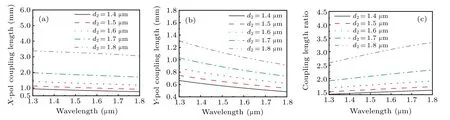
Fig.6.Effects of d2 on(a)CLX,(b)CLY,and(c)CLR of the proposed DC-PCF PBS.

Fig.8.Effects of Λ on(a)CLX,(b)CLY,and(c)CLR of the proposed DC-PCF PBS.
4.Performances of the proposed DC-PCF PBS
According to the above analyses, we finally choose the optimized structure parameters of the proposed DC-PCF PBS as follows:d1= 2.0 µm,d2= 1.7 µm,d3= 1.5 µm, andΛ=3.3µm.With these parameters,the calculated CLX,CLY,and CLR curves are shown in Fig.9.From Fig.9, the CLR value at wavelength 1.55µm is very close to 2.Next,we will analyze the performances of the proposed DC-PCF PBS, including the splitting length,ER,bandwidth,and IL.

Fig.9.Calculated variations of CLX, CLY, and CLR of the proposed DC-PCF PBS under optimized structure parameters.
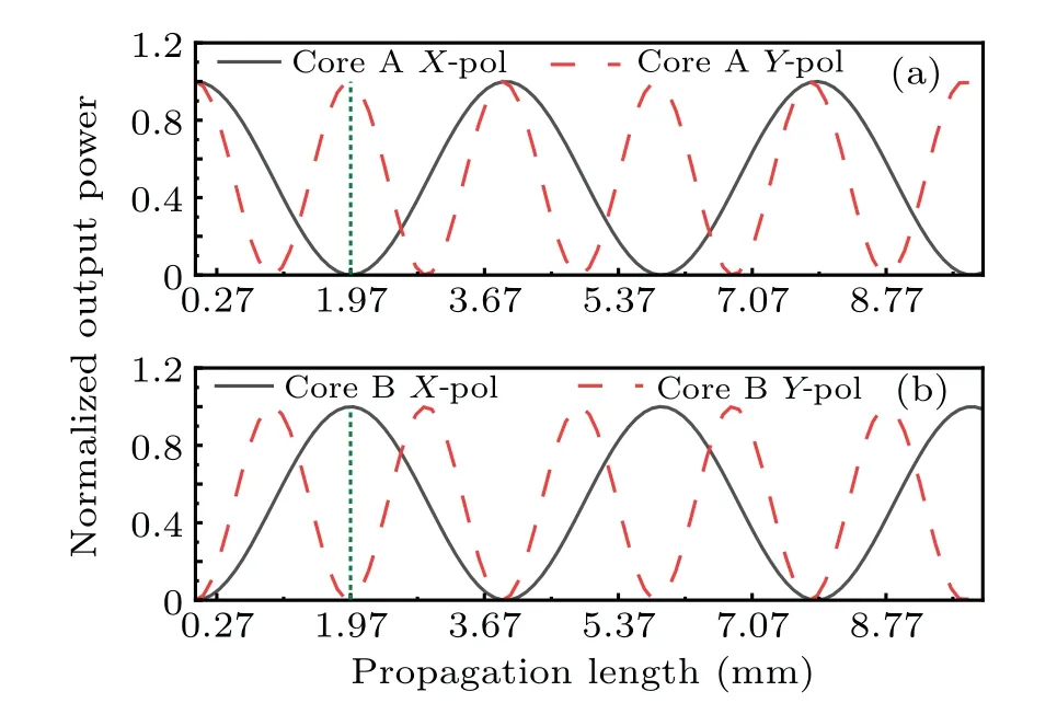
Fig.10.NOPs of X-pol light and Y-pol light in(a)core A and(b)core B of the proposed DC-PCF PBS on the assumption that the light beam at wavelength 1.55µm launches into core A.
When the light beam at wavelength 1.55µm is launched into the core A of the proposed DC-PCF PBS, the calculated NOPs of theX-pol andY-pol light in the cores A and B are shown in Fig.10.From Fig.10 it follows that theX-pol andY-pol lights have the periodic power exchanges between the two cores.This indicates that the mixed polarized light can be split into two orthogonally polarized light beams at a specific length.Here, the shortest splitting length is 1.97 mm.At the length of 1.97 mm,the NOP of theX-pol light reaches a minimum value while that of theY-pol light reaches a maximum value in the core A.In contrast, the NOP of theX-pol light reaches a maximum value while that of theY-pol light reaches a minimum value in the core B.Therefore,theX-pol light andY-pol light at a wavelength of 1.55 µm are completely separated in the two cores when the splitting length is 1.97 mm.
Figure 11 shows that the ER of the proposed DC-PCF PBS in core A at the shortest splitting length of 1.97 mm,has a sharp downward peak in the wavelength range from 1.3µm to 1.8 µm, and the extreme value of-81.45 dB appears at wavelength 1.552 µm.Moreover, the bandwidth of the ER less than-20 dB reaches 340 nm(1.38µm-1.72µm),which covers the S+C+L+U communication bands.
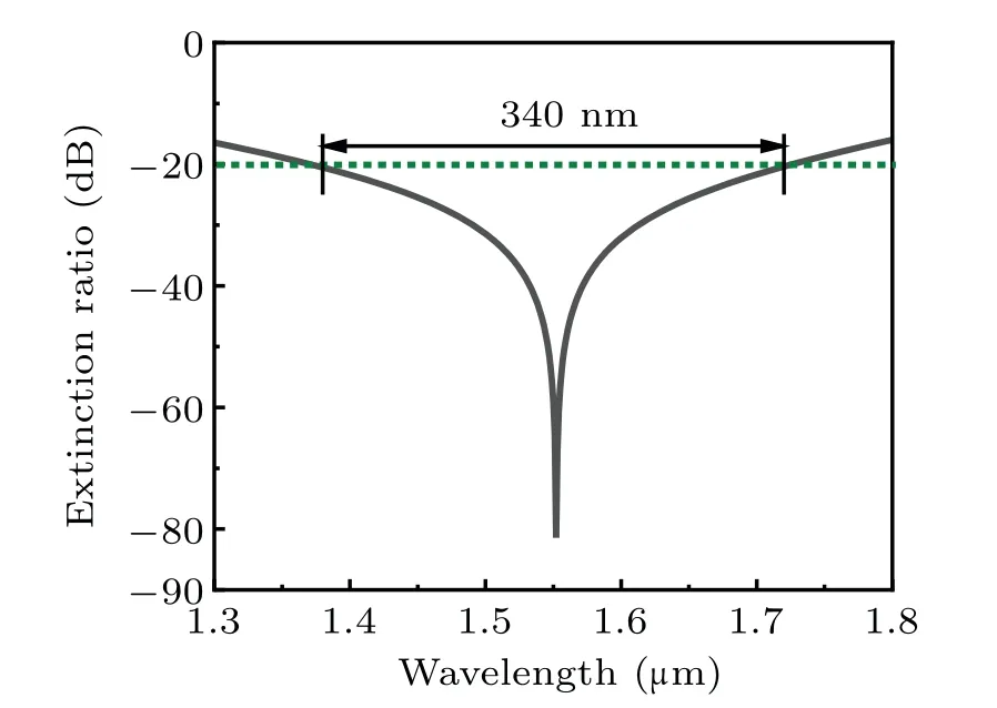
Fig.11.Variation of ER with wavelength of the proposed DC-PCF PBS for splitting length of 1.97 mm.
The comparisons between the proposed DC-PCF PBS and other reported structures are shown in Table 1.It can be seen from Table 1 that the proposed DC-PCF PBS has the largest bandwidth and highest ER.Although the PBSs in Refs.[19,38]have the shorter splitting lengths,their structures are more complex.Therefore,the proposed DC-PCF PBS has simple structure and good performances,and is possible to be fabricated in practice.
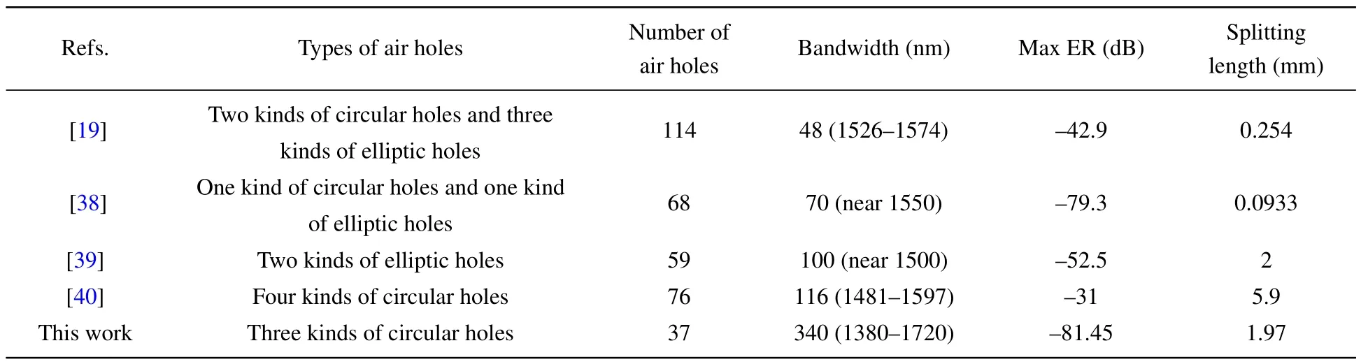
Table 1.Comparations between the proposed DC-PCF PBS and other reported structures.

Fig.12.Variations of the ER under the fabrication error 0.5%for(a)d1,(b)d2,(c)d3,and(d)Λ.
The fabrication tolerance of the structure parameters of the proposed DC-PCF PBS is important in practical applications.Figures 12(a)-12(d)show the changes of the ER under a fabrication error of 0.5% for different structure parameters.From Figs.12(a), 12(b), and 12(d), whend1,d2, andΛare changed by±0.5%, the working bandwidth of the DC-PCF PBS will be blue-shifted or red-shifted,but they can still maintain above 300 nm.And the ER at wavelength 1.55µm is kept below-20 dB.From Fig.12(c), the working bandwidth and ER of the proposed DC-PCF PBS are hardly affected whend3changes.
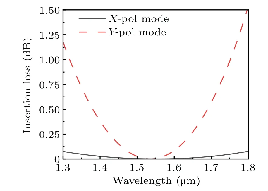
Fig.13.Valuation of IL of X-pol light and Y-pol light with wavelength in the wavelength range from 1.3µm to 1.8µm.
For the proposed DC-PCF PBS, the IL is also investigated by Eq.(7), and the results are shown in Fig.13.From Fig.13,the ILs of theX-pol light andY-pol light first decrease and then increase.In the wavelength range from 1.3 µm to 1.8µm,the IL of theX-pol light is lower than that of theY-pol light,and the two beams reach a minimum value at wavelength 1.55 µm, where the IL of theX-pol light andY-pol light are 5.35×10⁻⁶dB and 4.20×10⁻³dB,respectively.
5.Conclusions
In summary, a novel DC-PCF PBS with two kinds of lattices and three kinds of air holes is proposed.The FVFEM and dual-core coupled mode theory are used to analyze the propagation characteristics.The simulation results show that the bandwidth of the proposed DC-PCF PBS reaches to 340 nm, which covers the S + C + L + U communication bands,and the splitting length is 1.97 mm.Moreover,the maximum ER at wavelength 1.552µm is-81.45 dB,and the ER at wavelength 1.55 µm is-59.08 dB.Finally, the calculated IL of theX-pol light andY-pol light are 5.35×10⁻⁶dB and 4.20×10⁻³dB,respectively.The proposed DC-PCF PBS has the simple structure,ultra-wide bandwidth,high ER,and low IL.It has important applications in the field of all-optical communication and network.
Acknowledgement
Project supported by the National Key Research and Development Project of China(Grant No.2019YFB2204001).
- Chinese Physics B的其它文章
- Single-qubit quantum classifier based on gradient-free optimization algorithm
- Mode dynamics of Bose-Einstein condensates in a single-well potential
- A quantum algorithm for Toeplitz matrix-vector multiplication
- Non-Gaussian approach: Withstanding loss and noise of multi-scattering underwater channel for continuous-variable quantum teleportation
- Trajectory equation of a lump before and after collision with other waves for generalized Hirota-Satsuma-Ito equation
- Detection of healthy and pathological heartbeat dynamics in ECG signals using multivariate recurrence networks with multiple scale factors