
A New Synthesis Method for Sum and Difference Beam Pattern with Low Sidelobe
2011-03-09 11:57XUZhenhua徐振华HUANGJianguo黄建国ZHANGQunfei张群飞
Defence Technology 2011年2期
XU Zhen-hua(徐振华),HUANG Jian-guo(黄建国),ZHANG Qun-fei(张群飞)
(School of Marine Engineering,Northwestern Polytechnical University,Xi’an 710072,Shaanxi,China)
Introduction
Beam forming is a key technology in the array signal processing.Its essence is to weight the received array signals,and then make the main beam of pattern to point the expected signal and nulls to the strong interference signals,and improve the system performance.Thus,beam forming technology is widely used in communications,radar and sonar.In the array beam forming,generally speaking,the characteristic of low sidelobe is required.Theoretically,any kind of beam pattern with low sidelobe can be designed,however,various errors exist in the actual system,such as amplitude and phase errors of elements,position errors of elements,mutual coupling between elements and the mismatch of channel response,etc.,they limit to reduce the sidelobe level.In addition,we hope that the designed beam pattern have the best directivity or a narrow main lobe and low sidelobe,the design process has to balance the width of main lobe and the sidelobe level.Since the sum and difference beam pattern synthesis plays an important role in the incoming direction estimation and tracking,it is widely used in phased array radar and synthetic aperture sonar,and many scholars pay great attention to it;a lot of literatures have been published.The design of sum beam synthesis proposed by Chebyshev and Taylor was discussed in literature[1],and it could control the performance of sidelobe under the precondition of keeping the width of main lobe.The difference beam pattern was discussed by McNamara in literature[2],and it used the singular polynomial proposed by Zolotarev to obtain the difference beam pattern with constant sidelobe.McNamara also gave a discreteVilleneuve difference beam pattern,similar to the discrete n Villeneuve sum beam pattern.Taylor distribution used in sum beam pattern was proposed for a continuous aperture;a similar process was presented by Bayliss to control the height of sidelobe,and it was used to design the difference beam pattern.In literature[3],Dolph gave the weighting coefficients for uniform linear array,and they could be used to obtain the smallest beam width under given sidelobe level.To a certain extent,these methods solved the synthesis of the sum and difference beam pattern with low sidelobe.However,they had some shortcomings,such as more iteration times,large com-putational load and loss of extra freedom degrees.For solving these problems,a new synthesis method for sum and difference beam pattern with low sidelobe is proposed in this paper.It makes use of a phase coneweighting and Fourier transform pair relationship existing between the linear array factor and the element excitation to obtain the array element excitations from the given array factor iteratively.The iteration does not stop until the value of the array element excitations meets the initial sidelobe requirements.The method overcomes the defects of traditional methods.It is also effective for the pattern synthesis in the case of element failure.
1 Array Model
For convenience,the uniform linear array model is given in Fig.1.The array consists of M sensors with uniform element spacing d.The incoming signals form P narrow band far-field sources sk(t)(k=1,2,…,P)with center frequency f0in θk(k=1,2,…,P)are received by the array elements respectively.Suppose that the signals and noise are independent each other in different snapshots,and the noise is white,zero-mean complex Gaussian random variable with variance.The output of array element can be written as

where t=1,2,…,L,L denotes the number of data samples(snapshots),S(t)is the unknown signal waveforms,

where N(t)is unpredicted noise process,

A(θ)is the array manifold,

where c is the propagation velocity of signal.
The above model assumes
1)The transmission medium is uniform and isotropic,and the receiving array is located in the far field of the signal,so the signals can be regarded as plane wave;

Fig.1 Sketch of uniform linear array
2)The geometry size of array element is much smaller than the wavelength of the plane wave,and it has not directivity,the spatial gain is 1.The spacing d between array elements is much larger than the size of the array elements.The interaction between elements,such as the coupling,etc.,can be neglected.
3)The additive noise is stationary,Gaussian white noise with zero mean and variance σ2n,and any two elements are uncorrelated.The second-order moment of noise vector N(t)can be expressed as

2 Algorithm
Assuming a uniform linear array with M sensors and uniform spacing d,the far field beam pattern can be written as

where Amis the complex excitation of the mth element,k the wave-number,k=2π/λ,λ the wavelength,u=sinθ,θ the angle between far-field direction and array’s normal,AF the array factor,Bue(u)the element farfield pattern.From equation(9),it can be seen that the element excitation coefficients Amof the array and the array factor form a discrete inverse Fourier transform pair.AF is a periodic function with period λ /d relative to u.A discrete Fourier transform applied to AF in the period λ/d will yield the element excitations Am.By using Fourier transform relationship between them and the phase taper weighting method proposed in this paper,the sum and difference beam pattern with low sidelobe can be synthesized.
We know that,when the signals of elements are weighted uniformly to form the beam pattern,the weighting coefficients for different elements are the same,and their phases have a fixed difference[4].For a narrow band linear array with M elements,the beam forming can be expressed as

where s(θ)=[s1(θ),s2(θ),…sM(θ)]Tand means that,when DOA equals to θ,the incident signal of M elements sk(θ)can be expressed as

where ω =[ω1,ω2,…,ωM]Tis the complex weight for M element signals.The element pattern function can be expressed as B(θ)=20lg(|y(θ)|).The taper is a very effective method for inhibiting interference of sidelobe.The taper beam forming can be expressed as y(θ)= ωH[C·s(θ)],where ω is the uniform weighting coefficient,C=[C0,C1,C2,…,CM-1]is a window function used in the taper beam forming,· denotes vector inner product,i.e.,the product of two vectors’elements with the same position.Different from the uniform weighting beam forming,the taper beam forming has different amplitudes of the element weighting coefficients.Generally,the window functions are all symmetrical real vectors,and the middle weight coefficient has large value,however,while the bilateral weights decrease gradually and their phases also have a constant difference[5-7].The taper method and iteration need to give an initial set of M element excitation coefficients first.Then,according to the equation(9),the calculation of AF is carried out by using a K point's inverse FFT(K > M)and zero padding,also,making the sidelobe region of AF meet the sidelobe requirements.If the sidelobe samples of AF exceed the sidelobe thresholds,they will be corrected,keeping the rest samples of AF invariant.After that,a K point FFT is performed on the corrected AF to obtain an updated set of excitation coefficients.In these K excitation coefficients,only the M samples belonging to the array are retained,and other are set to zero.This iteration process will not stop until new AF satisfies the sidelobe requirements.In the process of iteration,dynamic range constrains are introduced by setting a lower limit to the updated element excitation coefficients in each iteration.In addition,if defective elements in the array occur,then the related excitation coefficients can be set to zero.This measure can ensure the sidelobe level optimal.
The algorithm’s flowchart is shown in Fig.2.
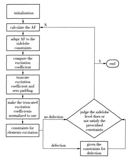
Fig.2 Algorithm flowchart
3 Simulations
3.1 Case of No Failure Array Elements
Suppose that a uniform linear isotropic array consists of 50 elements,the element spacing is half of the wavelength of signal,the sidelobe level SLL= - 40 dB,the dynamic range of the element excitations,defined as the ratio of their maximum amplitudes to the minimum,does not exceed 21 dB.In the synthesis,the direct and inverse FFTs are carried out in 1 024 points,and the maximum number of iteration times is 150.The synthesized sum and difference beam pattern is given in normalized form,as shown in Fig.3 and Fig.4.
3.2 Case of Array Element Failure
Suppose that the serial numbers of the defected elements are 8,12,20,22,25,26,27,29,and the other simulation conditions are the same as above.The simulation results are shown in Fig.5 and Fig.6.

Fig.3 Sum beam pattern synthesis of linear array with 50 array elements and-40 dB in sidelobe leve
4 Analyses
It can be seen from the simulation results that,given the sidelobe level,the sum and difference beam pattern synthesis can be effectively performed in the premise of keeping small variation of main lobe width.In the case without element failure,the synthesis efficiency,measured by statistically absolute error of sidelobe,is 99.64%and 98.77%,respectively.In the case of array elements failure,the synthesis efficiency is 90.03%and 79.67%,respectively.

Fig.4 Difference beam pattern synthesis of linear array with 50 array elements and,-40 dB in sidelobe level

Tab.1 Main lobe and sidelobe of sum beam pattern in iteration process

Fig.5 Sum beam pattern synthesis of linear array with 50 array elements and-40 dB in sidelobe level in case of element failure
5 Conclusions

Fig.6 Difference beam pattern synthesis of linear array with 50 array elements and-40 dB in sidelobe level in case of element failure

Tab.2 Main lobe and sidelobe of difference beam pattern in iteration process,for case of element failure
The proposed new synthesis method of sum and difference beam pattern with low sidelobe overcomes some defects in traditional methods,such as more searching times,much larger computational amount and poor robustness.It can effectively synthesize the sum and difference beam pattern,and also has a good synthesis effect in the case of array element failure.It will make up the influence of defects on the system performance.The proposed method will have important significance for practical engineering application.
[1]Van Trees H L.Optimum array processing[M].Beijing:Tsinghua University Press,2008:120 -135.(in Chinese)
[2]Schuler K,Wiesbeck W.Tapering of multitransmit digital beamforming arrays[J].IEEE Transon Antennas and Propagation,2008:2125 -2127.
[3]Keizer W P.Fast low sidelobe synthesis for large planar array antennas utilizing successive fast fourier transforms of the array factor[J].IEEE Transactions on Antennas and Propagation,2007,55(3):715 -722.
[4]Keizer W P N.Element failure correction for a large monopulse phased array antenna with active amplitude weighting[J].IEEE Transactions on Antennas and Propagation,2007,55(8):2211 -2218.
[5]SONG Kai-ge,GAN Quan,TANG Bin.A new method of digital beamforming of low sidelobe[J].Signal Processing,2009,5(5):777 -780.(in Chinese)
[6]ZHU De-zhi,YAN Feng-jun.Analysis about impact of unlform linear array defect on beam pattern[J].Modern Electronic Technique,2009,32(8):106 -108,111.(in Chinese)
[7]YOU Hong,HUANG Jian-guo.Detection of long distance object based on MVDR for Wideband under water passive acoustic home guide system[J].Acta Anmamentarii,2009,30(2):160 -164.(in Chinese)
猜你喜欢
Chinese Physics B(2022年11期)2022-11-21
汽车实用技术(2022年14期)2022-07-30
新高考·高三数学(2022年3期)2022-04-28
艺术评鉴(2020年2期)2020-03-23
新高考·高一数学(2017年5期)2018-03-04
中国钱币(2016年5期)2016-06-15
小说月刊(2015年6期)2015-04-23
天池小小说(2009年7期)2009-08-06
雕塑(1997年3期)1997-06-23

- Defence Technology的其它文章
- Study on CAD Data Interface to Geometry Description System
- Modeling and Simulation for Complex Repairable System with Built-in Test Equipment
- An Evaluation Approach for Operational Effectiveness of Anti-radiation Weapon
- An Orthogonal Wavelet Transform Fractionally Spaced Blind Equalization Algorithm Based on the Optimization of Genetic Algorithm
- Prefix Subsection Matching Binary Algorithm in Passive RFID System
- Research on Performance of U Separator in Sand and Dust Test System