
Numerical Simulation on Flow Control for Drag Reduction of Revolution Body Using Dimpled Surface
2011-03-09 11:57WANGJing王晶ZHANGChengchun张成春RENLuquan任露泉HANZhiwu韩志武
Defence Technology 2011年1期
关键词:王晶
WANG Jing(王晶),ZHANG Cheng-chun(张成春),REN Lu-quan(任露泉),HAN Zhi-wu(韩志武)
(1.College of Agriculture,Jilin University,Changchun 130062 Jilin,China;2.MOE Key Laboratory of Bionics Engineering,Jilin University,Changchun 130022 Jilin,China)
Introduction
The drag reduction effect and methods,especially the flow control using non-smooth surfaces have been paid much more attention in recent years.Walsh[1]found that riblet surfaces can develop a lower shear stress than that of smooth surfaces on the basis of fluiddynamic reasoning.Similar studies performed by Reif in Germany were motivated by observation on shark skin.Subsequently,many researchers studied the various riblet surfaces,including a shark skin replica,and confirmed that the riblet surfaces can reduce the skin friction drag[2-7].In recent years,many researchers have paid more attention to engineering of non-smooth surface from the perspective of bionics.A typical application is the swimming suit based on the hydrodynamics of a shark skin.The investigators realize that the dimpled surface can also have the fluid dynamic effects.Bearman and Harvey[8]found that,for Reynolds number of 4×10⁴to 3×10⁵,the dimpled circular cylinder has a lower drag coefficient than a smooth cylinder.It was measured that,at transonic speed,the revolution bodies with dimples can reduce the total drag by 3%[9].
In our past researches,we examined the drag reduction effect of bionic dimpled surface by wind tunnel tests.However,it is difficult to obtain the mechanism of drag reduction of the dimpled surface by experiments.Therefore,now,we focus our attention on the numerical analyses for the external flow of smooth and dimpled surfaces to obtain the drag reduction mechanism of the dimpled surface.
1 Modeling Approach
1.1 Governing Equation
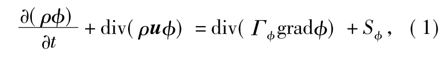
The governing equation can be writtenas where u is the velocity vector,and the components of u in x,y and z are u,v and w;φ is common variable;Γφis general diffusion coefficient;Sφis general source item.
Table 1 shows the concrete terms of Eq.(1)for a compressible steady state flow.

Table 1 Concrete terms of governing equation of flow
1.2 Turbulence Modeling
Some turbulence models are now widely used in engineering application,as they offer a good compromise between numerical effort and computational accuracy.SST(shear-stress transport)k-ω model developed by Menter[9]can effectively blend the robust and accurate formulation of the k-ω model in the near-wall region with the free-stream independence of the k-ε model in the far field was used in these fully turbulent simulations.The transport equations governing k and ω take the following form without regarding to the buoyancy
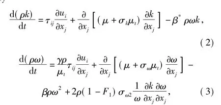
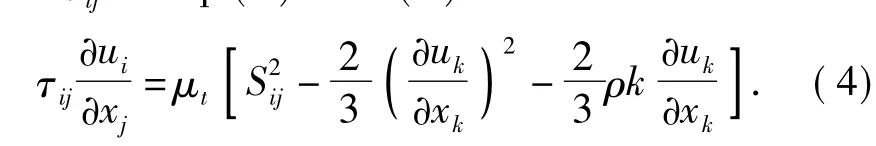
where τijis the turbulent shear stress.The production term of τijin Eq.(2)and(3)is
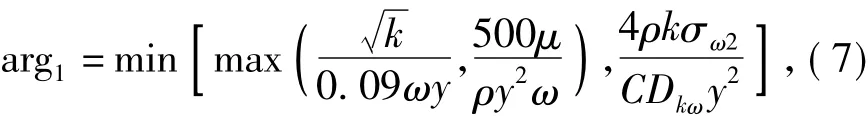
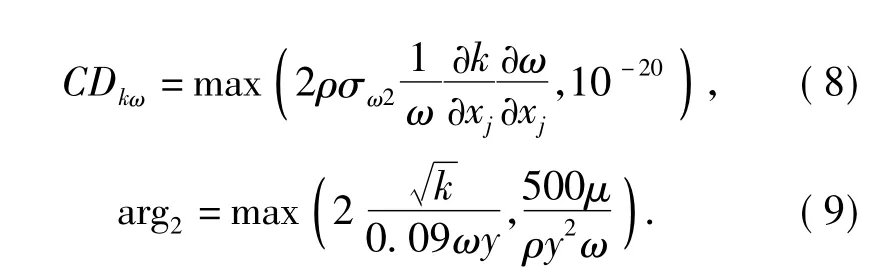
The blending functions F1and F2are defined as

where
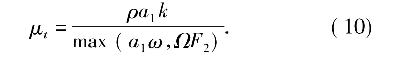
The turbulent eddy viscosity can be calculated by using following formula
The model constants can be calculated by using F1blending function,

where φ1represents a generic constant in the k-ω equations and φ2the same constant in the k-ε equations.
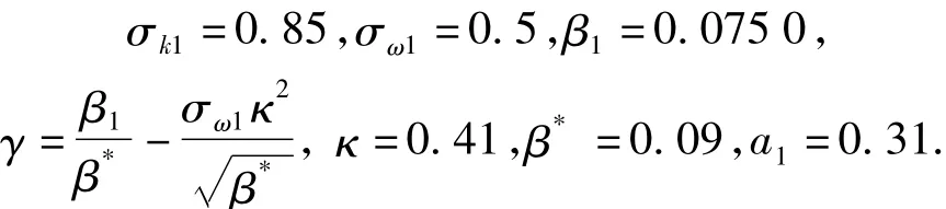
The k-ω model constants are given by
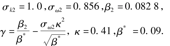
The value of k-ε model constants are
2 Computational Details
2.1 Computational Case
The revolution body with length of 517.5 mm and maximum diameter of 62.5 mm is shown in Fig.1.Fig.2 shows the position and dimensions of the dimples.The radius of the dimple is 1 mm;the depth of the dimple is 1 mm;the space between two adjacent dimples in axial direction is 4 mm.

Fig.1 Main dimensions of model of revolution body
2.2 Grids and Boundary Conditions
The computational region is meshed by unstructured hybrid grids with tetrahedral elements and triangular prism elements.The distance of the first layer near the wall is determined according to
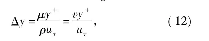
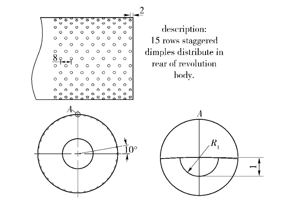
Fig.2 Dimensional parameters of dimpled surface
where uτis the wall friction velocity given by

By solving Eq.(12),we can obtain
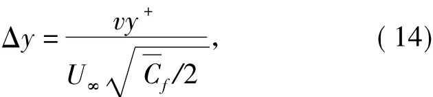
where y+is the dimensionless distance of the first layer to the wall.The appropriate range of y+suiting SST kω turbulence model is y+<5,in these simulations,y+=4.U∞is the flow velocity calculated by using

where Ma is the Mach number of flow,k the specific heat ratio of air,R the gas constant,and T the absolute temperature.k and R are 1.4 and 287 m2/s2K respectively.
The average friction coefficientcan be approximately calculated by using

where ReLis the Reynolds number based on the length of revolution body,which can be defined as
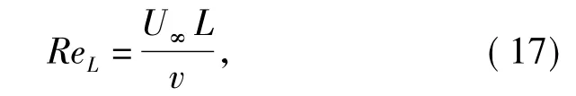
where L is the length of the revolution body,and v the kinetic viscosity coefficient defined as
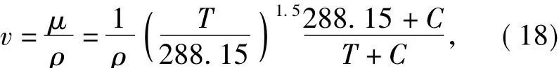
where T=299 K,ρ=1.185 kg/m3,C=110.4 K.
Thus,the distance between the first layer grids and the wall is Δy≈0.01 mm,and the boundary layer thickness δ is

Figure 3 shows the unstructured Cartesian hybrid grids with prism and tetrahedral elements.There are 10 layers of prisms over the surface of the revolution body.The dimpled region is provided with high-density meshes to observe the variation of the vortexes forming in the dimples.The computational region has 1.706 ×10⁶cells composed of tetrahedral and prisms approximately.
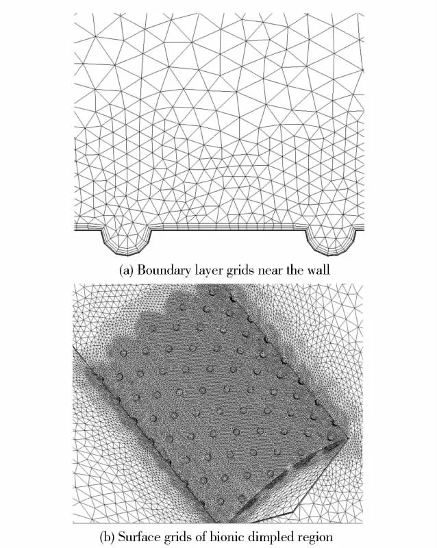
Fig.3 Grids in boundary layer dimpled region
As an axially symmetric body,the revolution body can be simulated in its quarter to reduce the amount of calculation.Thus,the computational region can be defined as a quarter of a cylinder.It is 1/4 of 20Rm×10L,where Rmis the maximum radius of the revolution body,L the length.
The pressure far-field boundary condition is used to model the compressible free-stream at Mach number of 0.4,the static pressure of 100 750.4 Pa,the temperature of 299 K.The angle of attack is α =0°.
3 Calculation Results and Analyses
3.1 Calculation Results
The drag reduction ratio of the dimpled surface can be defined as

where Csmoothis the drag coefficient of the smooth revolution body,and Cbionicthe counterpart of the dimpled one.According to Eq.(20),the drag reduction ratios of the viscous drag,the pressure drag and the total drag are all obtained.The viscous drag of the revolution body decreases by 8.05%,the pressure drag by 1.9%and the total drag by 6.24%.
3.2 Mechanism of Friction Drag Reduction
The viscous fiction stress of revolution body includes viscous shear stress and turbulent Reynolds stress and can be defined as

where μ is the dynamic viscosity coefficient,μtthe turbulent viscosity coefficient.The relationship of the instantaneous velocity vx,the time averaged velocityvxand the fluctuation velocity v'is vx=vx+v'.The friction drag reduction mechanism can be explained on the basis of Eq.(21).
Figure 4 shows the wall shear stresses of the dimpled and smooth revolution bodies.Evidently,the wall shear stress of the downstream of the dimples is reduced observably.Fig.5 compares the velocity to that of smooth body in the same location near the wall of the dimpled body,and it shows the wall shear stress reduction of the dimpled revolution body.It can be seen from Fig.5 that the flow speed in the dimples and downstream is visibly lower than that of the smooth body.In Fig.5(b),δ+is defined as

where Δy is the distance from monitor point to the wall of the model,δ is the boundary layer thickness.Form Fig.5(b),we can deduce that the dimples reduce the flow field velocity gradient near the dimpled surface,and increase the viscous sub-layer of the boundary layer.Therefore,the viscous shear stress decreases.
According to the physical factor of Reynolds stress,we know that the speed fluctuation can reflect the scale of Reynolds stress.Moreover,the ratio of its square root to the time averaged velocity is the turbulent intensity.Fig.6 compares the turbulent intensity and the turbulent kinetic energy of the dimpled body to the smooth one.From Fig.6,we can draw that the Reynolds stress is reduced,because the turbulent intensity near the dimpled surface is lower than that of the smooth one.The turbulent kinetic energy of the dimpled model,which is consumed by the turbulent fluctuation,is lower than that of the smooth one.
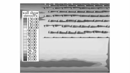
Fig.4 Wall shear stress comparison between dimpled and smooth revolution bodies
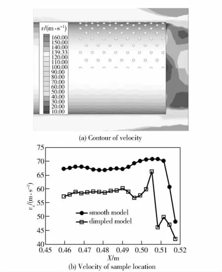
Fig.5 Velocity comparison between dimpled and smooth revolution bodies
In summary,the bionic dimpled surface reduces the viscous shear stress and the Reynolds stress simultaneously.Therefore,its friction drag is reduced evidently.
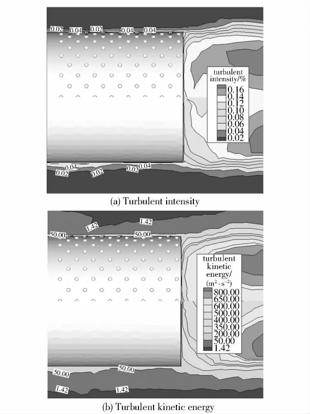
Fig.6 Turbulent comparison between dimpled and smooth revolution bodies
3.3 Mechanism of Pressure Drag Reduction
The pressure drag of the revolution body includes the base drag and the shock wave drag.The base drag can beexpressed as
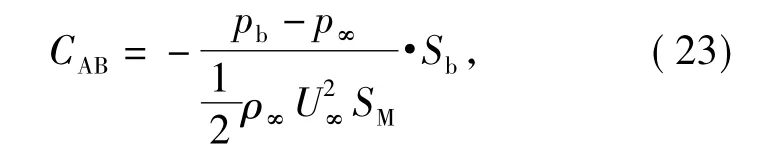
where Sbis the base area,and SMis the maximum cross section.Fig.7 compares the base pressures of the dimpled revolution bode to that of the smooth one.It indicates that the base pressure near the bottom of the dimpled body is higher than that of the smooth one.Namely,the dimples reduce the pressure difference.Accordingly,the pressure drag is reduced.
3.4 Analysis of Boundary Layer Control Using Dimpled Surface
Figure 8 shows the flow pattern in the dimple and the velocity vector on the dimpled surface.Evidently,there are a low-speed rotating vortexes forming in the dimples.Therefore,it is deduced that the dimples produce two effects.First,the low speed rotating vortexes in the dimples can be entitled an air cushion effect.Second,it produces friction drag against to the other area and results in a driving effect.
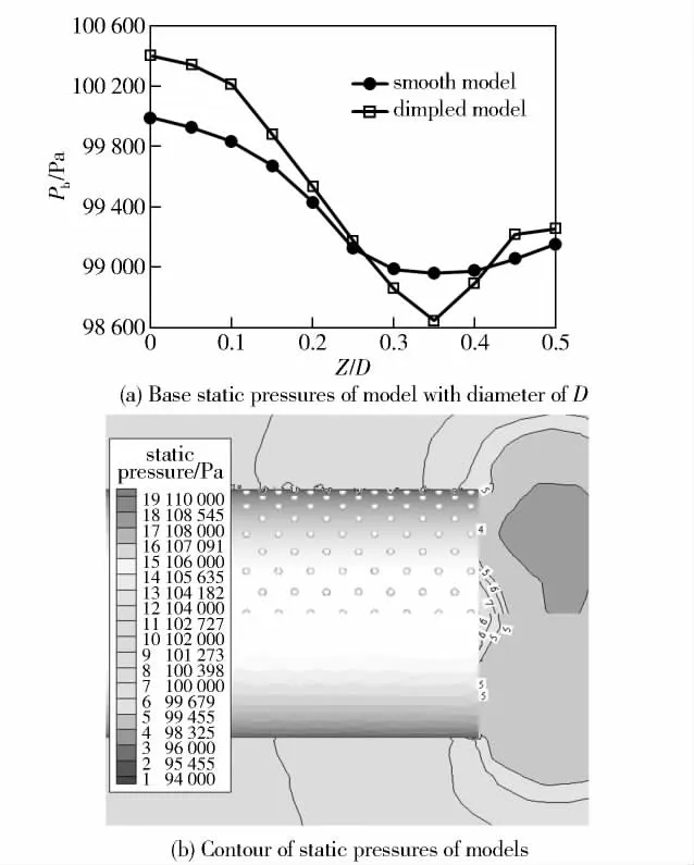
Fig.7 Base static pressure comparison between dimpled and smooth revolution bodies

Fig.8 Flow pattern of interior dimples and velocity vector of dimpled surface
Figure 9 compares the streamlines on the dimpled surface to that on the smooth one.Obviously,the streamlines of the dimpled revolution body are rarer than those of the smooth one.It indicates that the flow does not entry into the dimples,but passes over the air cushion and further explains the existence of the air cushion effect.
Fig.9 Streamline comparison between dimpled and smooth revolution bodies
4 Conclusions
Following conclusions can be drawn from the numerical simulation with SST k-ω model.
1)At the Mach number of 0.4,the dimpled surface arranged on the rearward of the revolution body reduces the viscous drag by 8.05%,the pressure by 1.9%and the total drag by 6.24%.
2)The dimples simultaneously reduce the wall shear stress and the Reynolds stress,then,the skin friction drag decreases.The dimples can also weaken the pumping action on the dead water region behind the revolution body caused by the external flow,which is the reason why the pressure drag decreases.
3)The basic reason of the skin friction drag reduction is that the dimples control and correct the boundary layer.The low speed rotating airflows in the dimples hinder the exterior airflow and the wall of the dimples to contact directly.It can be regarded as an air cushion effect.Secondly,the low speed rotating vortexes forming in the dimples can produce a friction drag against to the other area and results in a driving effect.
[1]Walsh M J.Riblets as a viscous drag reduction technique[J].AIAA Journal,1983,21(4):485 -486.
[2]Reif W E,Dinkelacher A.Hydrodynamics of the squamation in fast swimming sharks[J].Neues Jahrbuch für Geologieund Palaeontologie,(Abhandlungen),1982,164:184-187.
[3]Bechert D W,Bartenwerfer M,Hoppe G,et al.Drag reduction mechanisms derived from shark skin[C].Proceedings of the 15th ICAS Congress,London,1986:1044-1068.
[4]Choi K S.Near-wall structures of a turbulent boundary layer with riblets[J].J Fluid Mech,1989,208:417 -458.
[5]Walsh M J,Sellers W L,McGinley C B.Riblet drag at flight conditions[J].Journal of Aircraft,1989,26(6):570-575.
[6]Bechert D W,Bruse M,Hage W.Experiments with three dimensional riblets as an idealized model of shark skin[J].Exp Fluids,2000,28:403 -412.
[7]Bechert D W,Bruse M,Hage W,et al.Fluid mechanics of biological surfaces and their technological application[J].Naturwissenschaften,2000,87:157-171.
[8]Bearman P W,Harvey J K.Control of circular cylinder flow by the use of dimples[J].AIAA Journal,1993,31:1753-1756.
[9]REN Lu-quan,ZHANG Cheng-chun,TIAN Li-mei.Experiment study on drag reduction for bodies of revolution using bionic non-smoothness[J].Journal of Jilin University(Eng and Techn Ed),2005,35(4):431-436.
[10]Menter F R.Two-equation eddy-viscosity models for engineering applications[J].AIAA Journal,1994,32:1598-1605.
猜你喜欢
美与时代·城市版(2021年9期)2021-10-30
大众文艺(2021年16期)2021-09-11
健康体检与管理(2021年10期)2021-01-03
疯狂英语·新阅版(2020年4期)2020-05-29
大观·东京文学(2020年1期)2020-03-02
电影(2019年6期)2019-09-02
中华建设(2019年2期)2019-08-01
闽商文化研究(2019年2期)2019-05-21
南都娱乐周刊(2017年17期)2017-09-28
故事会(2011年8期)2011-04-21

- Defence Technology的其它文章
- Study on Outboard Inductive Damping Valve in Hydro-pneumatic Suspension
- Cooperative Navigation for Autonomous Underwater Vehicles Based on Estimation of Motion Radius Vectors
- Fuzzy Jamming Pattern Recognition Based on Statistic Parameters of Signal’s PSD
- Study on Instable Combustion of Solid Rocket Motor with Finocyl Grain
- A GNSS Signal Blind-decoding Algorithm at Low SNR
- Study of Load Modeling Technology on Hardware-in-the-Loop Simulator of Gun Servo System