
法国MBDA爆震和连续爆震波发动机的研发
2011-12-02 01:39FalempinFrancoisLeNaourBruno
Falempin Francois Le Naour Bruno
(MBDA导弹系统公司未来飞行器动力部,巴黎 ,法国)
INTRODUCTION
During past years,MBDA performed some theoretical and experimental works,mainly in cooperation with Laboratory of Combustion and Detonation at National Superior School of Mechanics& Aerospace in Poitiers,on pulsed detonation engine(PDE).These studies aimed at obtaining a preliminary demonstration of the feasibility of PDE in both rocket and airbreathing modes and at verifying the interest of such PDE for operational application:rocket and airbreathing modeexperimental evaluation,effect of filling coefficient,effect of a nozzle,thermal,mechanical,acoustic and vibrations environment generated,evaluation of different fuels,performance code development.
Due to its thermodynamic cycle,PDE has theoretically better performance than another classical propulsion concept using the combustion process(20% to 25%in term of thermal efficiency).Nevertheless,it is necessary to verify that this advantage is not fully compensated by the difficulties,which could be encountered for practical use of PDE concept or by the complex technology,which could be needed to implement in an operational flying system.
Indeed,PDE performance is driven by the following parameters:
(1)Quality of the pre-mixing;
(2)Value and nature of the needed energy for igniting the detonation;
(3)Duration of the high pressure level(depending of the filling coefficient);
(4)Maximum operating frequency depending of the minimum filling time.
And it is not so evident to optimise each of these parameters to obtain a real improvement of the global efficiency.
Moreover,PDE generates a severe vibration environment,which can imply higher more severe requirement for all on-board vehicle equipments or subsystems.
After some in house studies performed in national and international cooperation[1],MBDA is now cooperating with Defense Singaporean Organization(DSO)to develop a demonstration engine in order to really assess the feasibility and the interest of this propulsion concept.
Many authors are focusing their work on high performance concepts in order to take advantage of the high theoretical performance of PDE.That generally leads to complex arrangements and needs to optimize each of the main parameters of the engine.Such a propulsion systems correspond with high development and production and maintenance costs.
Considering that:
(1)Well known existing propulsion systems(rockets,turbojets,ramjets)have high performanceand are still being improved.
(2)For each application,related vehicles have been optimized to take the better advantage of these existing engine concepts.
MBDA and DSO do not aim at obtaining the maximum engine performance but try to take advantage of the specific characteristics of PDE to simplify engine and vehicle conception.
The considered application is an engine able to power a reusable subsonic UAV with cruising and loitering mission which corresponds with very demanding requirement in term of thrust range[2-3].
The use of rotating detonation wave can also be considered to reduce the environmental conditions generated by PDEwhile reducing theimportance of initiation issue and simplifying someintegration aspects.
Compared with PDE,this design allows an easier operation in reduced-pressure environment and an increase in engine mass flow rate and thrust-to-weight ratio.
Such a concept has been studied for a long time,particularly at Lavrentiev Institute for Hydrodynamics(LIH)in Novosibirsk.As it was done for PDE,specific experimental program has been performed by MBDA and Lavrentiev Institute to understand unsteady,3-D flow behind the detonation wave and to address some key points for the feasibility of an operational rotating wave engine for space launcher:
(1)Two-phase mixture detonation;
(2)Operating limits(injection pressure for example);
(3)Noise generated by the continuous detonation wave engine(CDWE)operating at several k Hz;
(4)Heat fluxes(intensity,areas)and cooling strategies;
(5) Composite materials(Carbon/Silicon Carbide)compatibility;
(6)Engine thrust vectoring capability.
On the basis of these results,a preliminary design of an operational engine is performed by taking into account all engine/airframe integrationissues in order to optimize the benefit of detonation wave engine.
In order to better assess the feasibility of such a system, specific experiments are performed to address somekey points like thrust vectoring,heat fluxes and material compatibility,operation in low pressure environment[4-6].In parallel,a dedicated effort is undertaken to develop an adapted numerical simulation tool.
Beyond these first steps,and with the partial support of French Space Agency CNES,MBDA designed a large scaleground demonstrator allowing to address all already mentioned issues for a continuous detonation rocket engine using LH2/LO x mixture.
1 CDWE OVERVIEW AND GENERALITIES
The main feature of CDWE is an annular combustion chamber closed on one side(and where the fuel injection takes place)and opened at the other end.Inside this chamber,one or more detonation waves propagate normally to the direction of injection(Fig.1).
Fig.1 CDWE principle
In fact CDWE is very close to a multitube PDE cluster running globally at very high frequency(typically several k Hz)and so the mean pressureinside the chamber is higher for a typical single tube PDE(as is the mean thrust per unit area).If for PDE the injection pressure could be as low as theambient pressure,in thecase of CDWE the injection pressure should be higher and this kind of engine is particularly well suited for rocket operation.
The flow inside this chamber is very heterogeneous,with a 2-D expansion fan behind the leading shock(Fig.2).The transversedetonation wave(BC and B′C′)propagates in a small layer of fresh mixture(AB′)near the injection wall.An expansion fan is then created and transforms the tangential speed of the hot gas in axial speed 5(Fig.3).The necessary condition for the propagation of a detonation wave is the continuous renewal of the layer of combustible mixture ahead TDW.The height of this layer h must be not less than the critical value h*for detonation.In the case of a LH2/LO2 engine,the dispersion of liquid oxygen droplets and the quick mixing of the components should befast enough to decrease thevalue of h*and to enable the realization of CD in small chambers.
Fig.2 Flow field in TD wave reference axis
Fig.3 Flow field in laboratory referenceaxis
2 SYSTEM STUDY AND ENGINE SIZING
On the basis of a semi-emperical performance model developed by LIH,thecomparison between an advanced liquid rocket engine(LRE)and CDWE is done previously by taking the same maximum pressureinside the combustion chamber of both engine(and not the same injection pressure).
It is found that the needed combustion chamber length for stabilizing the detonation process,could be very short,shorter than 200 mm and even close to 100 mm with H2-O2 mixture.Such a short combustion chamber length will be helpful to reduce the wetted area of the engine because a annular chamber exhibits an inherently greater wetted area than a classical combustion chamber of the same length.
With the capability to use a reduced length combustion chamber(and a smaller wetted area),CDWEwill have a slightly increased design flexibility than a conventional LRE,with the possibil
Fig.7 Mock-up design principle
Fig.8 General view of test bench at LIH
some basic experiments are first performed with LIH,taking advantage of their long experience in such a experiment:
(1) Experiments in combustion chamber(CC)with inner diameter of 50 mm,100 mm and 280 mm.
(2)Homogeneous(gas/gas)and heterogeneous(liquid/gas)mixture studied.
The experimental detonation chamber is fed with fuel and oxydizer supplied by pressurised tanks blow-down.Due to this,the test duration is limited(<1 s)and the test conditions are rapidly changing(Fig.9).In fact,as the process is very rapid,this operating modeis not an issue for the test validity(except maybe the total duration which can limit the heating of the wall preventing,maybe,possible isobare combustion).On the contrary,it provides a large variation of pressures and equivalence ratio,which allow proving the stability of the detonation process over a large range of feeding conditions.

Fig.9 Typical feeding conditions evolution during test run
Some main obtained results are:
(1)Detonation regime obtained in 100 mm diameter CCwith GH2/LO x;
(2)Detonation regime obtained in 330 mm diameter CC with kerosene/air;
(3)High thrust density achieved in small CC(275 daN for a 50 mm inner diameter kerosene/GO2 engine).
From these experiments,some key points can also bederived for the general sizing of a CDWE combustion chamber:
(1)The height of the fresh mixturelayer h is a function of the detonation cell size.
(2)The frequency of the engine is given by the ratio D/l,where D is the detonation velocity and l thedistance between two consecutives detonation waves,typically several k Hz,the length of the combustion chamber L should be longer than 80% of l(to ensure transition from subsonic to supersonic inside the CC).If not the detonation could be unstable.
Thanks to the blow-down operation,it is also easy to get a detailed knowledge of thestability domain of the detonation process.As an example,Fig.10 shows the stability domain obtain for a mixture of gaseous Hydrogen and Oxygen as function of specific mixture mass flow(related to the top injection wall area)and of equivalence ratio.
Fig.10 Stability domain-gaseous H2/O2 mixture
In this particular case,it has to be underlined that thedetonation waves speed is 2 770 m/s at equivalence ratio 1 when Chapman-Jouguet speed D cj is 2 840 m/s.But equivalent results can be obtained(depending of theinjection configuration)with other mixtures as shown in Table 2.
Table 2 Example of detonation wave speed compared with corresponding D cj
4 SPECIFIC ISSUES
4.1 Thrust vectoring capability
One of the peculiarities of CDWEis that the number of detonation waves inside the chamber is not constant and is a function of the combustible mix ture,the combustion chamber geometry and also the mass flow rate.For a given mixturein a given chamber,changing the mass flow rate(and the injection pressure)will change the number of detonation waves inside the chamber.
This could be explained with the assumption that behind TDW(and between two consecutive TWD),thereis a complex series of shock waves.If the mass flow rateis increased,the height of the fresh mixture behind two consecutive detonations is sufficient to support a new detonation wave(h>h*)and a shock induced combustion(a detonation)could occur and a new TDW appears.If the mass flow rate inside the combustion chamber is decreased,the height of the fresh mixture between two consecutive TDWs decreases and could be in sufficient to support a shock-indued combustion and TWD degenerates into a more simple shock wave.
This self-adaptation of the detonation to the fresh mixture local mass flow makes it possible to gain thrust vectoring with the local increase of the mass flow.Some experiments are done in a 100 mm internal diameter combustion chamber.The injection wall consists of 190 holes for the injection of fuel and oxidizer.In one series of experiments the equivalence ratio is changed in onehalf of the enginecompared with theother half.In another series,the injectors diameter is increased in order to double the local mass flow rate in one half of the engine.
Eight pressure probes(P1 to P8)are located along the circumference of the outer wall of the annular chamber.
In all experiments it is possible to obtain an increase of the thrust on one side of the engine.The most promising experiments show that a 30% increase of the thrust-wall overpressure is possibleif the mass flow rateis doubled.This increaseis lower than expected but the small diameter of the test engine limits the heterogeneity of the flow inside the combustion chamber.With a larger engine,a 100% increase of the thrust on oneside(compared with the other side)should be possible(Fig.11).A small shift of the maximum and minimum pressure values is also observed.Those extreme value seems to be located between P7and P8(maximum)and between P3and P4(minimum)instead of directly near P1 and P5.
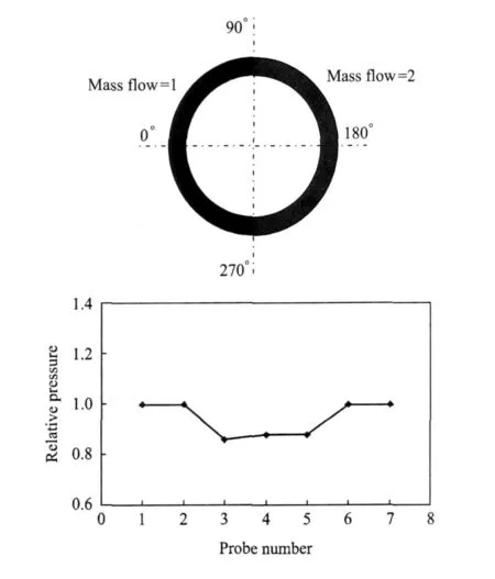
Fig.11 Pressure evolution along chamber circumference
Compared with LRE (with a gimbaled nozzle),this thrust vectoring capability is interesting because thereis no changein the thrust direction and the response time is limited only by the response time of theinjectors,which could be very fast,enabling the positive control of thevehicle attitude at high frequency without using much power.The complete pressure field and flow velocity should still be investigated to check the effect of the flow deflection and flow expansion in the nozzle.
4.2 Heat f luxes and cooling system
Due to the thin layer of detonation,the highest heat load inside CCoccurs near the thrust wall and decreases rapidly along the axial axis.
Wall temperatures in heat-sink combustion chambers are recorded with Hydrogen/Oxygen and kerosene/Oxygen mixtures(Fig.12).In Fig.12,point 1 is the detonation wave and points 2,3,4 are distributed along an axial line up to exit section.
The cooling system design could be critical because for metallic structures the mean heat fluxes near the thrust wall are measured between 12 and 17 MW◦m-2with local values even higher(with Hydrogen/Oxygen mixture).
This heat flux repartition is also very different from the oneobtained in LRE where the maximum heat fluxes occurs near the combustion chamber geometric throat.This point could be beneficial for the engine design because the vaporization of the injected oxygen will be faster and the mixing between hydrogen and oxygen will be better.
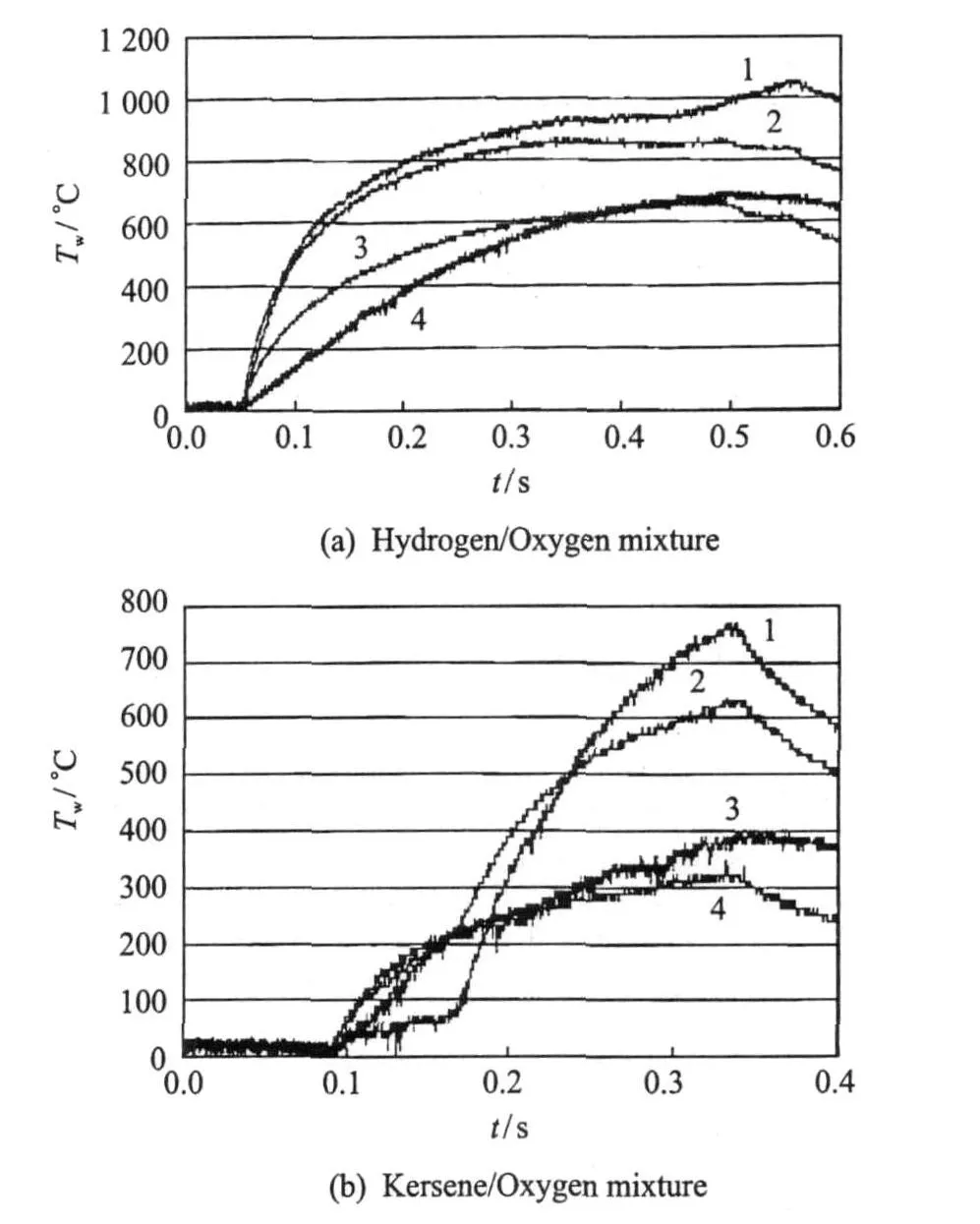
Fig.12 Evolution of temperature along axial line during test run
The high heat fluxes anticipated in a CDWRE lead to the issue of active cooling,a very difficult task with metallic structures with a wall temperature limited to the vicinity of 1 000 K.Composite materials could achieve higher wall temperature(up to 1 800 K)even in oxidizing conditions. After a careful review of existing products,some C/SiCcomposite materials are selected.Then,two composite parts,constituting the inner wall of the annular detonation chamber,have been designed and manufactured to be tested in the LIH 100 mm CDWE combustion chamber.Each of these two parts successfully sustained a dozen of short duration(0.5 s)experiments with-out apparent damage to the material surface(Figs.13,14).A new experiment series is performed with moresevereconditions(feeding pressure up to 2.5 MPa)during which the two samples aredamaged proving that this point is surely one key technology issue to becarefully addressed in the future.
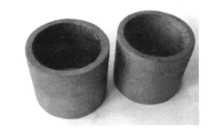
Fig.13 Two composite parts
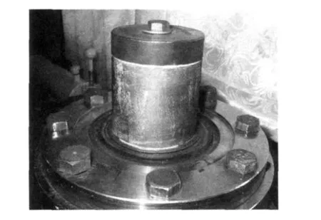
Fig.14 Part installed on chamber central body
4.3 Operation in space environment
Ignition of an enginein very low pressure environment could be a real problem,even for a conventional rocket engine.For CDWE operation,the lack of geometric throat adds to the potential difficulty of a sufficient filling of thechamber with no counter pressure.
This issue is investigated using LIH 100 mm ID detonation chamber connected to a 0.5 m3vacuum tank with an initial pressure of 6 k Pa.
The first step is to investigate the effect of the injection conditions(specific mass flow and equivalence ratio),and after that to decrease the ignition energy until it is impossible to achieve an initiation of the detonation.
Blasting copper wires are used for initiating the detonation inside the combustion chamber and ignition energy could be changed with the change of theapplied voltage and the wire diameter.
Gaseous hydrogen and oxygen at ambient pressure are selected for those experiments and injection pressure between 0.16 and 2.50 MPa(for hydrogen),and 0.5 and 1.1 MPa(for oxygen)allowed the investigation of ignition within a wide range of low specific mass flow(between 21 and 57 kg◦ s-1◦ m-2).This mass flow rateis ten times lower than mass flow used in previous experiments but is mandatory given the relatively small volume of thevacuum tank.
From the pressure signal and the direct visualization of the flow with high-speed camera(Fig.15),it is possible to determine the minimum injection conditions for the positive ignition of the TDW system inside the combustion chamber as a function of the mixture equivalence ratio.
In the case of a positive TDW initiation,the static pressureinside thecombustor increases to a much higher level(between 0.810 5 and 1.251 05 Pa)than when no detonation occurs(due to the lack of a geometric throat at the exit of the combustion chamber).
It is found that increasing the specific mass flow rateincreases both lean and rich ignition limits of the engine and that it is possible to start a TDW at very low combustion chamber pressurein a wide range of equivalence ratio(0.5—1.7),with a very low amount of energy(less than 1 J)(Fig.16).
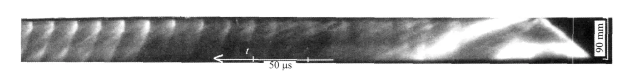
Fig.15 Visualiation of low ambiant pressureignition phase
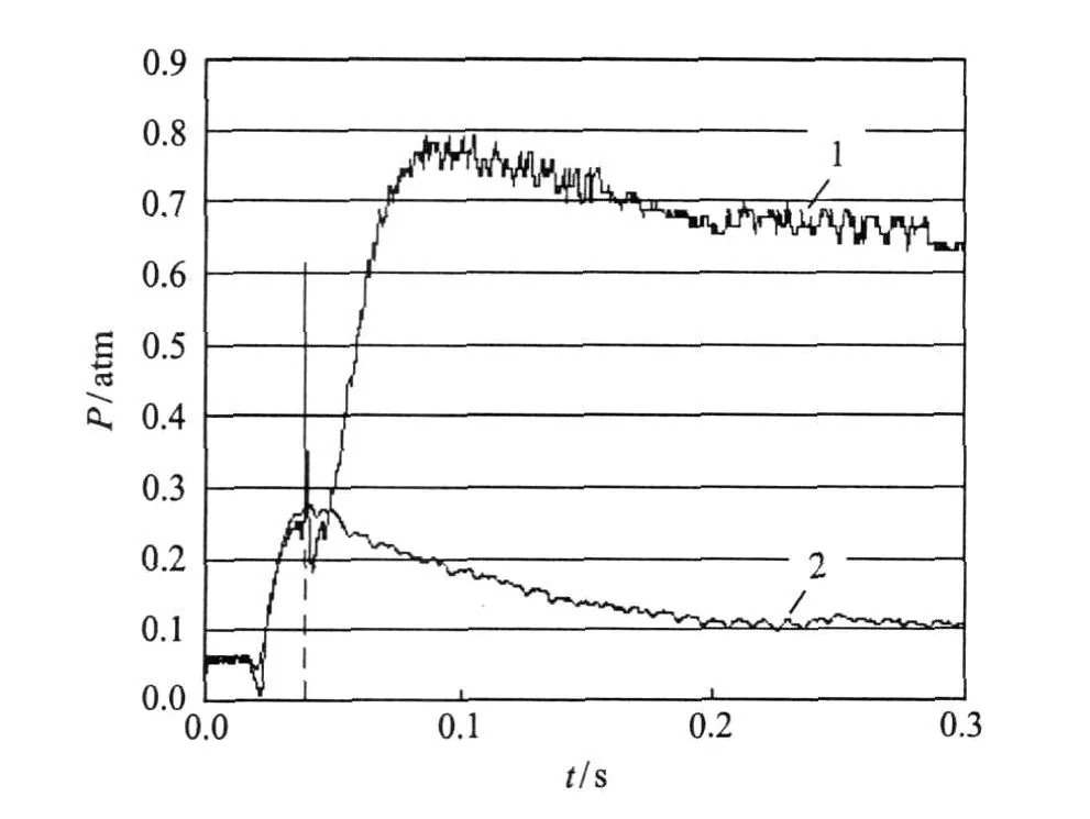
Fig.16 Two cases of ignition(1)and non-ignition(2)
5 NUMERICAL SIMULATION
With MBDA support,ICARE Lab is developing different levels of numerical simulation to provide,in middle term,needed tools to develop and optimize actual engines.The first approach consisted in performing Euler computation using periodical boundaries conditions[10].Even if these computation have still to be refined,they already report the right overall operation and constitute a very good support to better understand the detonation wave self-ignition process(Fig.17).
Such computation allow also at determining the stream lines into the chamber(in engine axis).Fig.18 shows that these stream lines are not too much inclined and should not lead to strong skin friction losses.
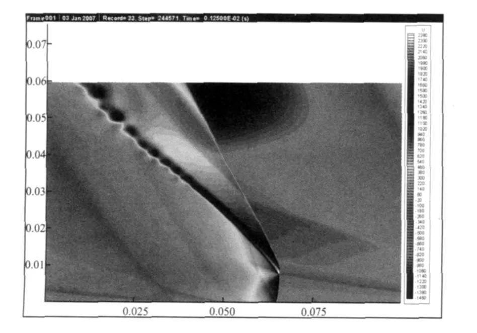
Fig.17 Exampleof computation results obtained by ICARE
6 DEMONSTRATION ENGINE
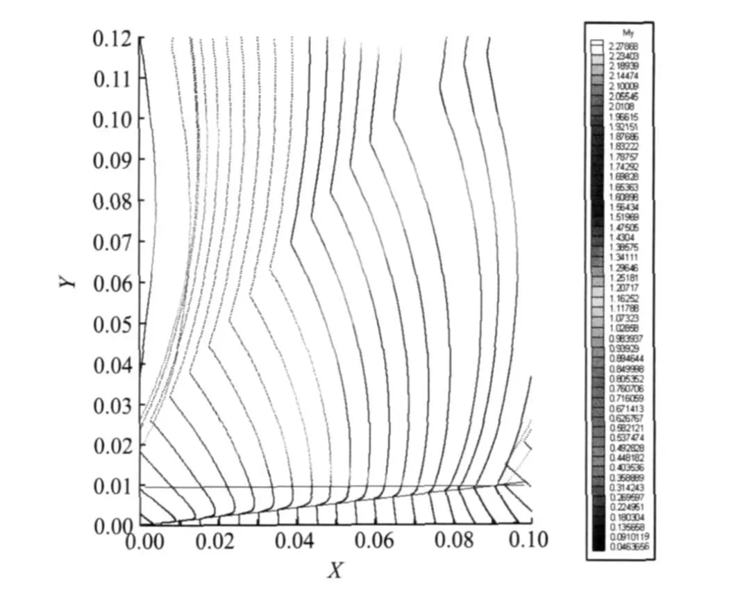
Fig.18 Trajectory of 20 particles released from top injection wall
Based on previous studies and the growing potential of such concept,a demonstration engine is designed.This large scaleengine(Fig.19)is to be manufactured and tested in existing test facility.Thecombustion chamber is 350 mm(external inner diameter)and 280 mm(internal inner diameter)and will beable to operate with GH2/GO2 or GH2/LO2 or liquid hydrocarbon/air with the change of supply lines and injection wall. This engine mock-up is modular and actively cooled.
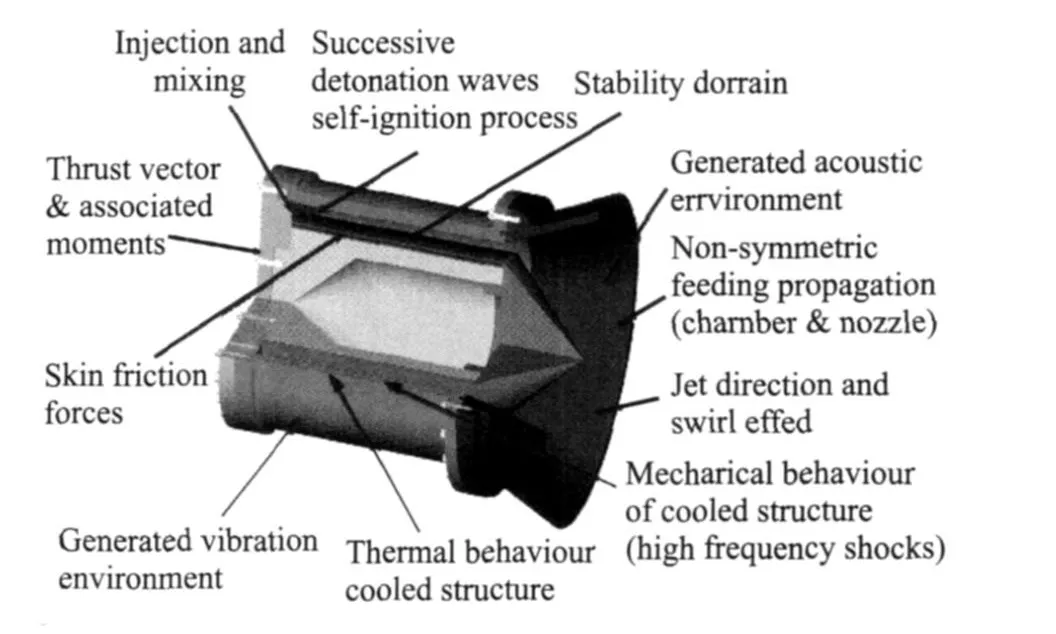
Fig.19 CDWE demonstration engine
With H2/O2,the injection pressure will be limited(between 1.0 and 1.5 MPa)and resulting mean pressure inside the combustion chamber with the envisioned mass flow rate(between 12 and 15 kg/s,depending on the equivalence ratio)is expected near 0.5 M Pa,a value sufficient to deliver several thousands daN of thrust.Moreover,the engine will be equipped with a complete weighing system providing thrust vector compo-nents and corresponding moments
Thanks to its modularity,the engine will be used,in a first step,as a non-flying workhorse allowing to address all the key points such as:
(1)Effect of injection configuration and conditions(2-phases mixing);
(2)Stable operation domain and key influencing parameters;
(3)Thermal and mechanical strength of the combustion wall(fuel-cooled structure,high frequency mechanical shocks);
(4)Effect of disymmetric injection on thrust vectoring when including a full nozzle;
(5)Generated environment(vibration and acoustics).
In the second step,the modularity will allow to progressively replaceall the engine components by flight-worthy ones in order to finally obtain a flight-worthy demonstrator which will be tested to really assess the achievable performance when taking into account all the technology issues.
As a first step in the development of this demonstrator,and with the support of EADS Group,MBDA designs and manufactures a preliminary small scale demo based on works done with Lavrentiev Institute(Fig.20).This 100 mm diameter mock-up is under testing within MBDA Bourges Subdray test facility.In the first step,the small scale demo is tested with pure hydrogen.Then,a mixture of methane and hydrogen will be used.Test duration is about 3 to 4 s.
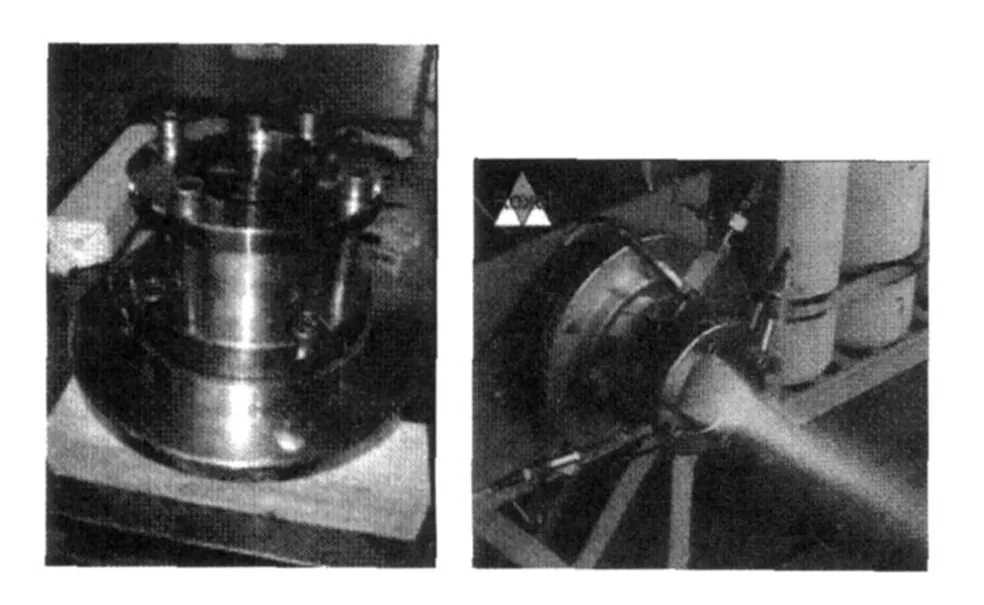
Fig.20 Small scale preliminary demo under testing
7 CONCLUSION
MBDA has been leading R&T works in cooperation with the Lavrentyev Institute of Hydrodynamics on the Continuous Detonation Wave Engine.
The mixtures used in the different experiments are mainly GH2&LO2 or LHC&GO2.The goals of those experiments are to address some key technology points in order to beable to evaluate theglobal interest of an engineusing TDW for the combustion process.It is found that such engine could deliver impressive thrust in a very small package(275 daN for internal diameter of 50 mm and length of 100 mm,kerosene-oxygen engine)and that could be increased with the use of a diverging nozzle.
Due to thegeometry of thecombustion chamber,a plug or aerospike nozzle seems to be the best design,thethrust vectoring capability of this engine(with the local change of the mass flow rate)being a way to solve theproblem of attitude control.
The heat fluxes are very high but located mostly near the injection wall.This point will help the gasification of the liquid component injected inside the combustion chamber.The transverse flow velocity could also help the mixing of the fresh products,but also the mixing of the fresh mixture with thedetonation products.
Some preliminary tests are performed to evaluate the capability of C/SiC composite materials to sustain thevery severemechanical environment generated by the rotating detonation waves.Beyond these first steps,a full scale demonstrator is designed and should be developed in 2010 allowing a large set of test from basic experiment to improve knowledge and understanding of the TDW process to technology demonstration test including fuel-cooled structure validation. By waiting,a small scale preliminary demo is designed and manufactured and will be tested in Spring 2010.
Authors particularly thank Dr.Sergey Zhdan and Dr.Feodor Byokovskiy for their key contribution in all experi-mental works performed on CDWE as well as Dr Dmitry-Davidenko for his outstanding contribution to numerical simulation activities.
[1] Daniau E,Zitoun R,Desbordes D,et al.Effetcs of nozzles of different length and shape on the propulsion performance of pulsed detonation engines[C]//High-Speed Deflagration and Detonation.Moscow:Elex-KM Publishers,2000:251-262.
[2] Daniau E,Falempin F,Zhang G,et al.Preliminary work for a pulsed detonation engine demonstrator[C]//14th AIAA/AHI Space Planes and Hypersonic Systems and Technologies Conference.Canberra:[s.n.],2006:AIAA-2006-7957.
[3] Zhang G,Jiang Y T,Foo H S,et al.First steps for thedevelopment and testing of a pulsedetonation engine for UAV application[C]//15th AIAA International Space Planes and Hypersonic Systems and Technologies Conference.Dayton:[s.n.],2008:AIAA-2008-2681.
[4] Daniau E,Falempin F,Zhdan S,et al.Detonation wave propulsion systems:First step toward operational Engines[R].ISABE-2005-1302,2005.
[5] Daniau E,Falempin F,Bykovskiy F A,et al.Pulsed and rotating detonation propulsion system:first step toward operational engines[C]//AIAA/CIRA 13th International Space Planes and Hypersonics Systems and Technologies.Capua:[s.n.],2005:AIAA-2005-3233.
[6] Falempin F,Daniau E,Getin N,et al.Toward a continuous detonation wave rocket engine demonstrator[C]//14th AIAA/AHI Space Planes and Hypersonic Systems and Technologies Conference.Canberra:[s.n.],2006:AIAA-2006-7956.
[7] Falempin F,Bouchez M.Fully axisymmetric airbreather concept for space launcher—First application to a micro space launcher[C]//International Aerospace Congress.Glasgow: IAF,2008:IAC-08-C4.5.6.
[8] Davidenko D M,Gokalp I,Kudryavtsev A N.Numerical study of the continuous detonation wave rocket engine[C]//15th AIAA International Space Planes and Hypersonic Systems and Technologies Conference. Dayton: [s.n.],2008: AIAA-2008-2680.
[9] Davidenko D M.Numerical study on the annular nozzle optimization for rocket application[C]//16th AIAA/DLR/DGLR International Space Planes and Hypersonic Systems and Technologies Conference.Bremen,Germany:[s.n.],2009:AIAA-2009-7390.
[10]Davidenko D M,Eude Y,Gökalp I.Ideal performance of acontinuous detonation wave rocket engine fed with hydrogen-oxygen mixture[C]//ICPCD 2010.Saint-Petersburg:[s.n.],2010.
猜你喜欢
军事文摘(2022年19期)2022-10-18
军事文摘(2022年9期)2022-05-30
凤凰动漫(军事大王)(2022年1期)2022-04-19
军民两用技术与产品(2021年10期)2021-03-16
电子制作(2018年2期)2018-04-18
医学研究杂志(2015年11期)2015-06-10
小朋友·快乐手工(2015年5期)2015-06-06
汽车技术(2015年11期)2015-01-09
西北工业大学学报(2014年4期)2014-03-25
中国医学科学院学报(2013年3期)2013-03-11
 Transactions of Nanjing University of Aeronautics and Astronautics2011年1期
- Transactions of Nanjing University of Aeronautics and Astronautics的其它文章
- 拉压、扭转载荷下铸铝合金的亿周疲劳性能研究
- 使用液态化学循环的高热效率动力研究
- 端墙形状对蒸汽涡轮效率的影响
- FATIGUE LIFE PREDICTION METHOD FOR IMPACTED LAMINATES
- VIBRATION NUMERICAL ANALYSISOF COUNTER-ROTATING TURBINE WITH WAKE-FLOWUSING FLUID-STRUCTURE INTERACTION METHOD
- EXPERIMENTAL STUDY OF FORCED SHOCK TRAIN OSCILLATION IN ISOLATOR UNDER ASYMMETRIC INCOMING FLOW