
Large deflection of annular throttle-slices in shock absorbers
2012-06-21 01:58HELiping贺李平GULiang顾亮XIAOJieping肖介平
HE Li-ping(贺李平), GU Liang(顾亮), XIAO Jie-ping(肖介平)
(1.Beijing Institute of Radio Measurement,Beijing 100854,China;2.School of Mechanical Engineering,Beijing Institute of Technology,Beijing 100081,China;3.Department of CAE and Performance Integration,Beijing Automotive Technology Center,Beijing 100021,China)
The superposed annular throttle-slices of automobile shock absorbers are multilayer annular plates.Their largest deflection has great impact on the characteristics of the shock absorbers[1-3]and need to be accurately calculated.Refs.[4-6]gave the analytical formulas of large deflection for a single throttle-slice by specifying the ratio of inner to outer radius of the throttle-slice.However,these formulas can’t be used in general situations.Another analytical formula of large deflection for a single throttle-slice was deduced in Refs.[7],but it haven’t been used for superposed throttle-slices yet.Although the annular throttle-slices could be considered as single throttle-slice according to the equivalent thickness method[8],the method is based on small deflection theory and is not suitable for large deflection situations.
A general analytical formula of large deflection for throttle-slices was deduced in this paper by combining Chien-perturbation method with finite element method (FEM).The analytical formula was verified and showed accurate results for calculating large deflection of annular throttle-slices in shock absorbers.
1 Mechanical model
Annular throttle-slices in shock absorbers are clamped at inner edge and free at outer edge as shown in Fig.1,whereqis the uniform pressure applied to the throttle-slices,b,athe inner and outer radius respectively,wthe deflection,andnthe number of slices.It is assumed that the forces between the throttle-slices are uniform.
2 Analytical solution
2.1 Von Kármán equations of single annular throttle-slice
For a single annular throttle-slice subjected to uniform pressureq,Von Kármán equations in the form of axial symmetry[7]are

Fig.1 Mechanical models of annular throttle-slices
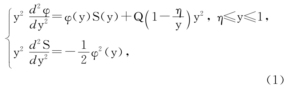
Theannularthrottle-sliceisclampedatinner edge,andfreeatouteredge,sotheboundaryconditionscanbeexpressedas

2.2 Solution by perturbation method
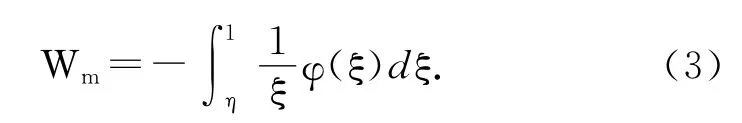
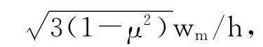
Wm,the dimensionless deflection of throttleslice at outer edge,is set as the perturbation parameter:
The undetermined functionsφ(y),S(y)andQinEq.(1)canbeexpandedintopowerseriesofWm,asfollows:
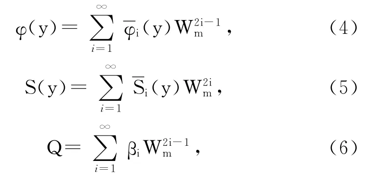
Sothestiffnesscurveequationoflargedeflectionofannularthrottle-sliceis

2.3 Analytical solution of superposed annular throttle-slices
Eq.(7)can be rewritten as
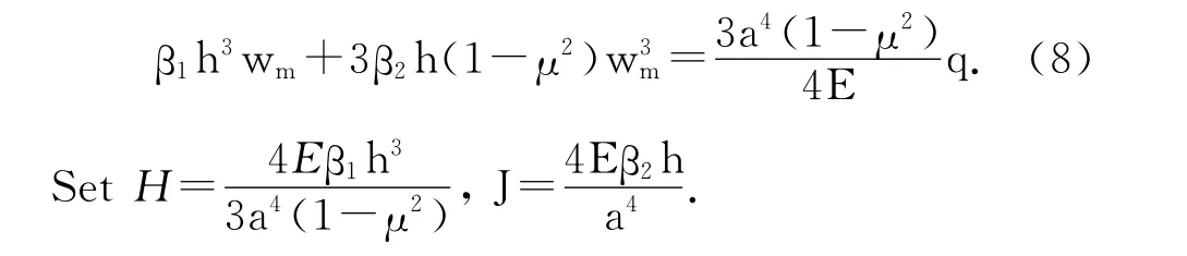
SothatEq.(8)canbesimplifiedto

For the first,…kth,…nththrottle slice,Eq.(9)can be written respectively as follows:
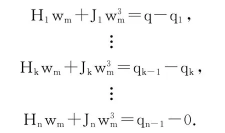
Summing up thenformulas above gives
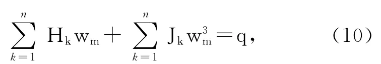
whereHk,Jkcorrespond toHandJrespectively for the thickness of throttle-slicehk.
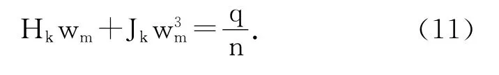
Eq.(10)is the general formula of large deflection for annular throttle-slices in shock absorbers.For a single throttle-slice,Eq.(10)can be simplified to Eq.(9).For superposed ones which are composed of the same thicknesshk,Eq.(10)can be simplified as
3 Numerical tests and curve fitting
While it is crucial to get the two undetermined coefficientsβ1andβ2ascanbeseenfromEq.(7),itisdifficulttoobtainananalyticalformulabecauseofthecomplexityofboundaryconditions.Therefore,numericaltestswerecarriedoutbased onFEMinthispaper.Theanalyticalformulaof largedeflectionforannularthrottle-slicescould beobtainedthroughcurvefittingofβ1andβ2.
3.1 Finite element model of annular throttle-slice
Finite element analysis software ANSYS was used for the numerical tests.The 8-node structural shell element(SHELL93)with large deflection characteristic was used for simulation of the annular throttle-slice.SHELL93is the higher order of 4-node quadrangular shell element,which is better for the simulation of curved boundaries,and gets higher accurate results by using fewer elements than the lower order element.The FEM solution will be converged to an exact solution with increasing element density.So the establishment of higher accurate finite element model needs finer element density.
Takea=20mm,b=10mm,n=1,h=0.3mm,E=206GPa,μ=0.3,q=0.2MPafor example.Takingintoaccountthesymmetry,finiteelementmodelsof1/4throttle-slicewithdifferentelementdensitieswereestablished(Fig.2).Fig.3showstherelationbetweentheFEMnumeri-calsolutions(we)ofthelargestdeflectionofthe throttle-sliceattheouteredgeandthevariouselementdensities.
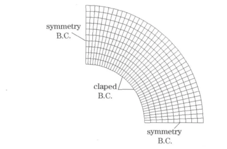
Fig.2 Finite element model of1/4 throttle-slice(mesh10×40)
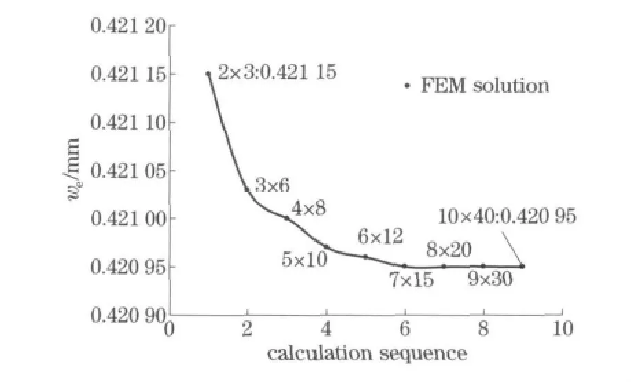
Fig.3 Deflection values at the outer edge for various element densities
Althoughalowelementdensitycanmeetthe requirementsofaccuracy(Fig.3),the1/4throttle-slicewasdividedinto10partsalongradialdirectionand40partsalongcircumferentialdirectionrespectivelyforahigheraccuracy(Fig.2).
3.2 Finite element numerical tests
Theratioofinnertoouterradiusofthe throttle-slice,α=b/a,isbetween0.30and0.80usually.Seth=0.3mm,E=206GPa,μ=0.3,q=0.2MPa,anda=20or30mmrespectively.Tab.1liststhenumericaltestresults.
3.3 Curve fitting
Whileβ1andβ2arefunctionsofαandthe Poisson’sratioμ,μhaslesseffectonthedeflectionofthrottle-slicerelativity.Sotheerrorsfromμcouldbeignoredbysettingμ=0.3.Substituting deflectionvaluesinTab.1intoEq.(7)givestwoundeterminedcoefficientsβ1andβ2,aslistedin Tab.2.
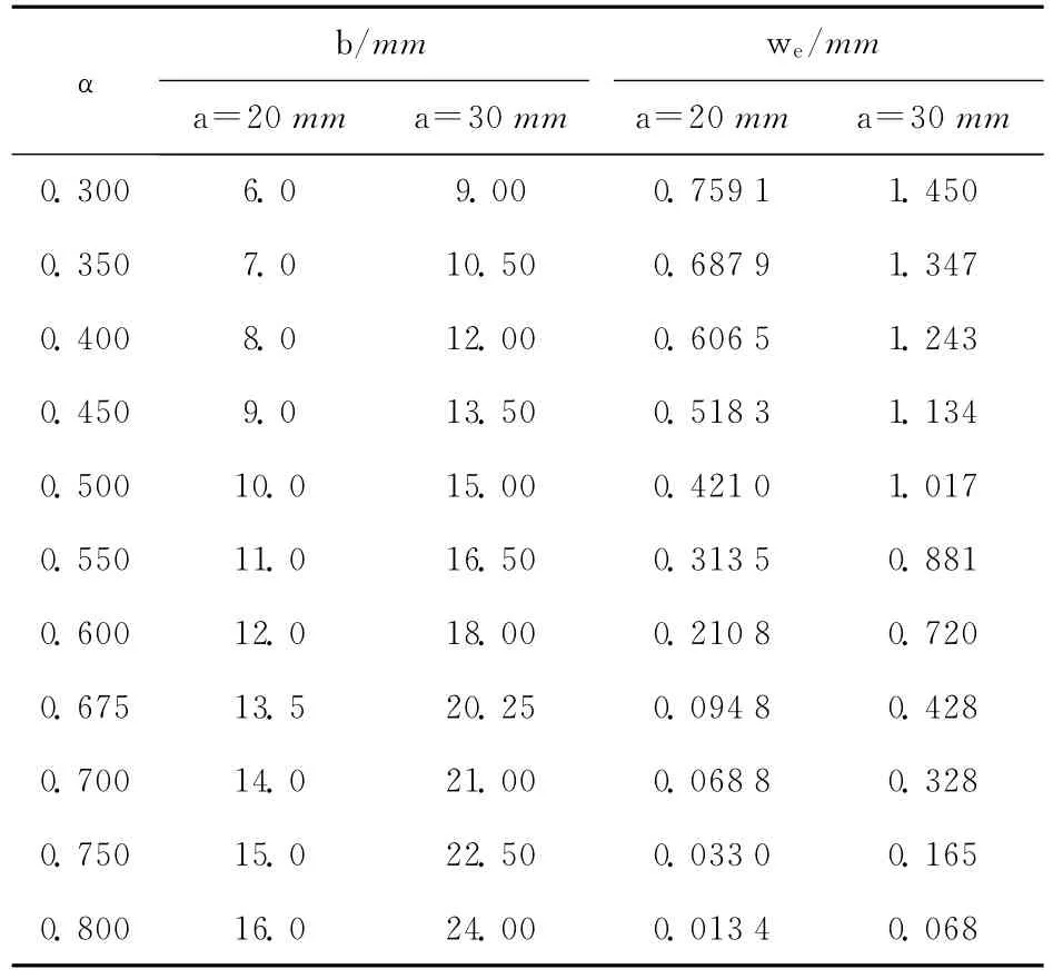
Tab.1 Deflection values of throttle-slice in outer edge
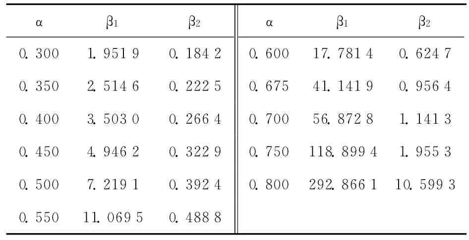
Tab.2 Undetermined coefficientsβ1 andβ2
Lorentzianfunctionwasusedtononlinear leastsquarescurvesub-fittingofβ1andβ2for higheraccuracy,whichareshowninFig.4.
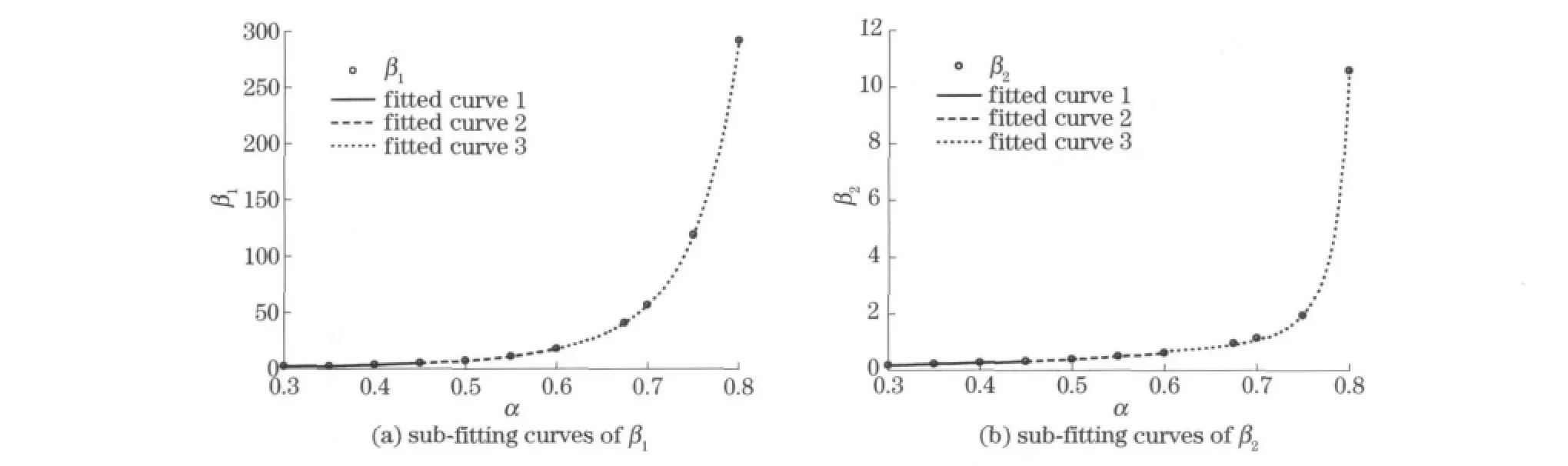
Fig.4 Sub-fitting curves ofβ1 andβ2
Meanwhile,thesub-fittingcurveequations canbeobtained:
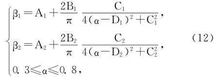
where the undetermined coefficients are listed in Tab.3.
Substitutingβ1,β2intoEq.(10)giveswm,the largestdeflectionofannularthrottle-slicesattheouteredge.
4 Accuracy verification and discussion
The FEM solution was presented to verify the accuracy of the analytical solution.In this section,the structural parameters and material properties of throttle-slices are set as follows unless otherwise noted:a=16mm,b=8mm,α=0.50,E=206GPa,μ=0.3,n=3,h1=0.10mm,h2=0.15mm,h3=0.20mm,andq=0.2MPa.
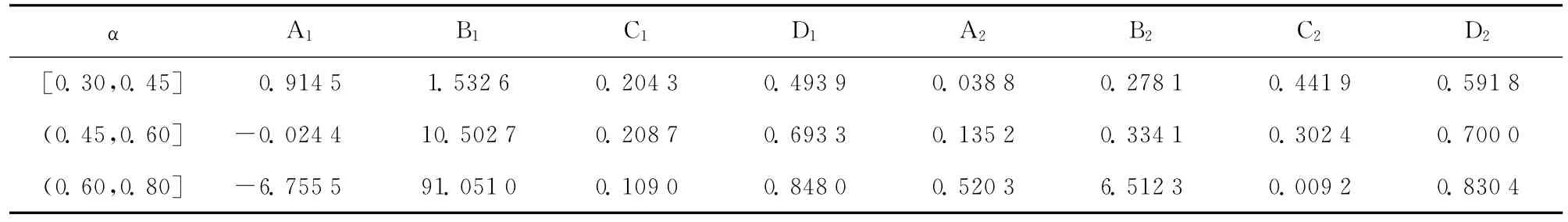
Tab.3 Undetermined coefficients of Lorentzian function
Eachthrottle-sliceshouldbedividedinto10partsalongradialdirectionand40partsalong circumferentialdirection.Frictionbetweenthrottle-sliceswasignoredconsideringtheeffectoflubricatingoilfilm.Takingintoaccountthesymmetry,1/4finiteelementcontactmodelofsuperposedthrottle-sliceswasestablished.
Theanalyticalsolutionswerecomparedwith FEMsolutionswithn,a,α,E,μandqvaryingin acertainrangerespectively,andtheiraccuracy wasverified.
4.1 Different pieces
Seta=16mm,b=8mm,E=206GPa,μ=0.3,q=0.2MPa,n=1-5.Tab.4liststhecomparisonbetweenanalyticalandFEMsolutions.
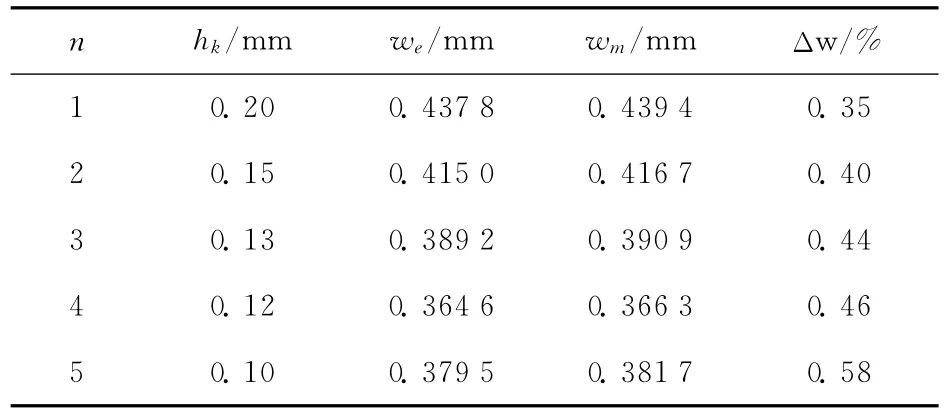
Tab.4 Deflection values of analytical solutions vs.FEM solutions for various n
InTab.4,Δwistherelativeerrorbetweenthe analyticalandFEMsolutions.
4.2 Same ratio of inner to outer radius
Settingα=0.5tomakesurebandavaryproportionally.Fig.5showsthecomparisonbetween analyticalandFEMsolutions.
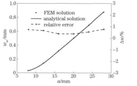
Fig.5 Deflection curves of analytical solutions vs.FEM solutions forα=0.5
4.3 Same inner radius
Settingb=8mmtomakesureavariesandα∈[0.3,0.8].Fig.6showsthecomparisonbetweenanalyticalandFEMsolutions.

Fig.6 Deflection curves of analytical solutions vs.FEM solutions for b=8 mm
4.4 Other variables
MakesureE,μandqvaryrespectively.Fig.7showsthecomparisonbetweenanalyticalandFEM solutions.
Fig.7bshowsthatthePoisson’sratioμhas lesseffectonthedeflectionofthrottle-slicesthan otherparameters.Sotheerrorscausedbynotconsideringμinβ1andβ2canbeignored.
Thenumericalcomparisonsaboveverifythat theanalyticalformula(Eq.(10))oflargedeflectionforannularthrottle-slicesisaccurate(datashowsthattherelativeerrorislessthan3%)andabletomeettherequirementsofengineeringdesigns.
5 Conclusions
①Ananalyticalformulaoflargedeflection forsinglethrottle-slicewasdeducedbasedon Chien-perturbationmethod,finiteelementnumericaltestsandcurvefitting.Aformulaforsuperposedthrottle-sliceswasfurtherdeducedandgeneralized.Thegeneralanalyticalformulacanbe usedforthedeflectioncalculationofbothasingle throttle-sliceandsuperposedones.
②Theanalyticalformuladeducedinthis papercanalsobeusedforsmalldeflectioncalculationofthrottle-slices,sincethesmalldeflection theoryisthesimplifiedformoflargedeflectiontheory.
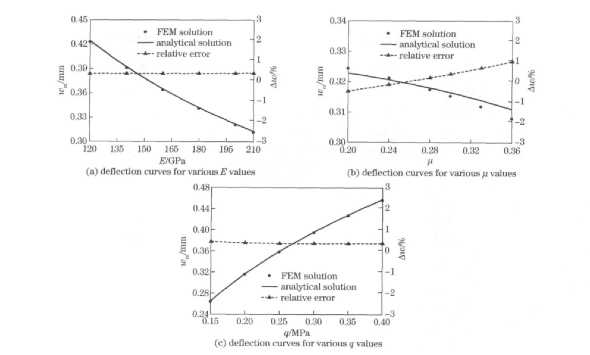
Fig.7 Deflection curves of analytical solutions vs.FEM solutions for various E,μ,q values
③Toensuretheaccuracyoftheanalytical formula,finiteelementmodelofthrottle-slices withhigheraccuracywasestablished.The Lorentzianfunctionissuitableforcurvefitting.Thenumericaltestsverifythattheanalyticalformulahassatisfactoryaccuracy.
[1]Duym S.Simulation tools,modelling and identification,for an automotive shock absorber in the context of vehicle dynamics[J].Vehicle System Dynamics,2000,33:261-285.
[2]Duym S,Stiens R,Reybrouck K.Evaluation of shock absorber models[J].Vehicle System Dynamics,1997,27:109-127.
[3]Zhou Changcheng,Zheng Zhiyun,Gu Liang,et al.Study on the availability opening size of throttle and affection to the velocity characteristic of shock absorber[J].Journal of Beijing Institute of Technology,2007,16(1):23-27.
[4]Li Youde,Li Jing,Song Dafeng,et al.A research on the deformation of spring valve plate in automotive shock absorbers[J].Automotive Engineering,2003,25(3):287-290.(in Chinese)
[5]Chen Yijie,Gu Liang,Yang Zhanhua,et al.Research on the large deflection of shock absorber throttle slice[J].Machinery Design & Manufacture,2008(10):90-92.(in Chinese)
[6]Chen Yijie,Gu Liang.Experiment and analysis of large deflection of throttle slice of hydro-pneumatic spring[J].Journal of Jilin University,2009,39(2):388-392.(in Chinese)
[7]He Liping,Gu Liang,Xin Guoguo,et al.High-precision analytical formulas of large deflection problem for annular throttle-slice in shock absorbe[J].Transactions of Beijing Institute of Technology,2009,29(6):510-514.(in Chinese)
[8]Zhou Changcheng,Gu Liang.Superposition throttleslices opening size and characteristic test of telescopedamper[J].Chinese Journal of Mechanical Engineering,2007,43(6):210-215.(in Chinese)
(Edited byCai Jianying)
 Journal of Beijing Institute of Technology2012年2期
- Journal of Beijing Institute of Technology的其它文章
- Artificial neural network modeling of mechanical properties of armor steel under complex loading conditions
- Optimization of the carrier tracking loop for GPS high dynamic receivers
- Vibration test of micro machined gyroscope based on high speed photography and SURF
- Experimental validation method of elastic thin rod model for simulating the motional cable harness
- Calculation methods of lubricant film pressure distribution of radial grooved thrust bearings
- Development of an occupant restraint system model and parametric study on equivalent crash pulse in vehicle frontal offset crash