
Velocity Correction and Measurement Uncertainty Analysis of Light Screen Velocity Measuring Method
2012-07-25 06:21ZHENGBin郑宾ZUOZhaolu左兆陆HOUWen侯文
Defence Technology 2012年4期
ZHENG Bin(郑宾),ZUO Zhao-lu(左兆陆),HOU Wen(侯文)
(1.National Defense Key Laboratory,North University of China,Taiyuan 030051,Shanxi,China;2.Institute of Intelligent Machines,Chinese Academy of Sciences,Hefei 230031,Anhui,China)
Introduction
Light screen velocity measuring method has the advantages of high accuracy,convenience to use,high working reliability,non-contact measurement,so it has been wildly used for the velocity measurement of flying bodies in military industry[1].Two screens are placed at the sides of designated measuring point along a ballistic trajectory.By measuring the distancesand the moving timetiof which the moving body moves between the two screens[2-3].The average velocityof the moving body at the midpoint of the two screens can be obtained from Eq.(1).

Equation(1)is very simple,but the obtained result is the average velocity of the midpoint.approaches to instantaneous velocity ifsis enough small.When the velocity attenuation of the flying body is linear,can be treated as instantaneous velocity.This kind of velocity measuring and processing method has been widely ratified at home and abroad,and the corresponding operational procedures have been developed[4-5].It is a widely used and effective method.However,the velocity correction is necessary in some new applications,such as the velocity measurement of moving body which has complex velocity attenuation.Some key questions about it are discussed hereafter.
1 Velocity Correction in New Application ofLightScreen Velocity Measuring Method
1.1 New Application of Light Screen Velocity Measuring Method
In a military research project,a standard velocity measuring device is used for measuring the velocity of a bigger moving body,its mass is about 100 kg,crosssectional area is about 1 m2,and it is launched along the track.The arrangement of the measuring system is the same as that of the general method,as shown in Fig.1.
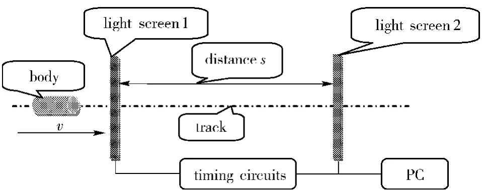
Fig.1 Schematic diagram of velocity measuring system
In Fig.1,the velocity to be determined is the velocityν0at the point of screen 1 on the ballistic line.In fact,the velocity attenuation of object during its motion between the screens is complex and nonlinear,and is limited by the arrangement of the devices.A big error would be produced when the average velocityis taken as the approximation ofν0,so the correction is necessary.
1.2 Velocity Correction Equation
Equation(2)of the velocity correction can be derived from the velocity test model shown in Fig.1.

wherev0(m/s)is the velocity of the specified measuring point,i.e.the velocity at screen 1;(m/s)is the measured velocity at measuring point,i.e.the velocity at the midpoint of the two screens;s(m)is the distance between the two light screens;ti(s)is the time interval of that the object passes though two light screens;ρ(kg/m3)is the air density;Cdis the wind drag coefficient;A(m2)is the windward area of the object;m(kg)is the mass of object;μis the sliding friction coefficient;g(m/s2)is gravity acceleration.
The deriving process based on aerodynamics and actual conditions is as follows.
During the motion,the body to be measured is subjected to the air resistanceFbalong the ballistic line and the friction forceFtfrom the track,which is given by Eq.(3).

The air resistanceFbis

In reality,ρcan be determined by looking up the air density table;Cd≈1 for vertical planar object,0.5 for spherical object and 0.28~0.4 for general vehicle[5].The sliding friction of the object can be derived by the formula of Friction resistance,which is given by Eq.(5).

whereμis taken as 0.15 for the rails.
The accelerationacan be obtained


wherec1is determined by initial conditions.
Supposing that the velocity of the body isv0when it arrives at screen 1 and the starting timet0=0 s,thenc1can be obtained by Eq.(8).

Equation(8)is substituted into Eq.(7),

Based on the displacement formula,the distancescan be obtained by Eq.(10),and the velocity att0isv0.

The integral Eq.(10)is solved,and we have

Finally,Q1andQ2are substituted into Eq.(11)to obtain Eq.(2).
1.3 Verification and Application of Velocity Correction Formula
A velocity measuring system is established according to the principle stated above,and the experimental conditions are as follows:the temperature is 20 degrees Celsius;the air densityρis 1.205 kg/m3;the distance between the screens is 2.006 6 m(average value of 8 times);the coefficient of sliding friction on the tail is 0.15;the gravity acceleration in the experimental area is 9.8 m/s2;the timing frequency is 80 MHz;the windward area of the object is 0.8 m2;the wind resistance coefficient is approximate to 1;the mass is 101 kg.Then the test results areti=0.052 13 s,ν'0=39.32 m/s,and the corrected velocity of the designated point isv0=40.36 m/s.The difference Δv'betweenv0andv'0is not a constant and it changes withti.The relation between Δv'andtiis shown in Fig.2.
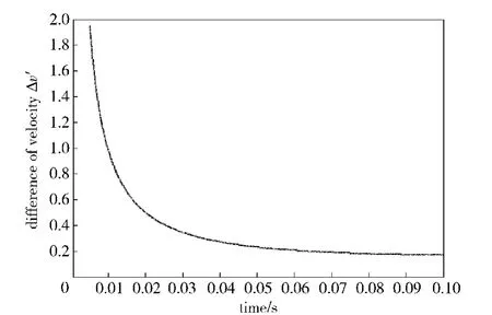
Fig.2 Variation of velocity correction value with time
The original light screen velocity measuring method can be used for new application after such velocity correction.The test results and velocity correction have been accepted by users in practice.
2 Analysis of Measurement Uncertainty
In practical engineering,because of the effect of multifarious factors such as measurement errors,dispersivity of parameters,modeling errors and so forth,an uncertainty exists in many problems.Therefore,we cannot use a traditional method to deal with the modeling and the solution any longer,but should seek an uncertainty analysis method[6].In the recent years,ISO and NIST guidelines and recommendations provides a framework for analyzing and communicating the measurement uncertainties.However,the new method of velocity correction was proposed and the new components of measurement uncertainties were introduced in this paper.But the original measurement uncertainties were still effective.So we should analysis the measurement uncertainty again.
2.1 MeasurementUncertainty Componentsin Original Light Screen Velocity Measuring Method
The original measurement uncertainties in the original light screen velocity measuring method include:the uncertainty caused by the error of repeated measurement of the distance,the uncertainty caused by the indication error of the measuring tool(i.e.the graduation error of the steel rule and the change of ambient temperature),the uncertainty caused by the velocity direction not vertical to the screen,the uncertainty caused by the counting error of the timer,and the uncertainty caused by the delay error of photoelectric conversion and so forth.As stated previously,the light screen velocity measuring method has been widely used and the corresponding operational procedures have been developed,and the reasonable measurement uncertainty analysis method has been established.So those uncertainties can be solved as a consequence according to their distributions,which is described instructions in detail in Ref.[7 - 11].
2.2 New Uncertainties Components Introduced by Velocity Correction
There are many physical quantities which should be measured in Eq.(2),and their uncertainties are difficult to be obtained.Moreover,based on Ref.[6],the uncertainties can also be computed from Eq.(12).
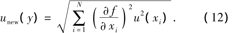
The analyzing and calculating processes are omitted here.But the actual analysis and calculation show that the new uncertainty values introduced by velocity correction are great,which the major uncertainties components of the velocity measuring system are shown in Fig.1.Thus the standard measurement uncertaintyuccan be obtained by Eq.(13),

whereu1、u2…uNare the uncertainties in original light screen velocity measuring method.
3 Practical Calculation of Measurement Uncertainty in New Application of Light Screen Velocity Measuring Method
Taking the confidence probabilityP=Pc=0.997 3,(based on 3σprinciple).Since the degree of freedomνobeystdistribution,the coverage factork=tPc(νc)can be obtained by looking up thetdistribution table according to calculatedνc,then the final expanded uncertainty isU=kuc.unewvalue(0.1 m/s)is obtained by substituting the measured and calculated values into.
4 Conclusions
For the velocity measurement of big moving bodies which have complex velocity attenuation,the principle of velocity correction was proposed considering the effects(air resistance,friction force,etc)based on the light screen velocity measuring method,the velocity correction equation was derived,and the application range of velocity measuring method was extended further.This principle of velocity correction has been actually used in some military research projects,and the better results were gained.Its technical ideas or methods can be used in the similar cases.Meanwhile,the measuring uncertainties were analyzed and calculated by considering the new components of measuring uncertainties caused by velocity correction.The results show that the error of the velocity measuring system increases because of the new measuring uncertainties.
[1]TANG Xiao-rong,WANG Bin,GAO Ning.The measuring uncertainty analysis of laser light screens[J].Nuclear Electronics& Detection Technology,2009,9(5):1044-1046.
[2]Gill G S,Amod Kumar.Velocity measurement system for small caliber projectiles[C].Proceedings of the World Congress on Engineering,London.2008,4:441 -445.
[3]Kalonia R C Mohan,Chander Bahuguna,Mathew B B,et al.Small caliber projectile velocity measurement system based on a single laser source and a single detector[J].Journal of Scientific and Industrial Research,2011,9(9):762-766.
[4]ZHANG Zhi-quan,WANG Lei,XU Da.Analysis of projectile shock wave's influence on measure of laser screen[J].Optical Technique,2008,12(4):203 -205.
[5]ZHANG Jin-lei,LEI Yu-cheng.Simulation analysis of aerodynamics used in automobile modeling[J].Agricultural Equipment& Vehicle Engineering,2009,5(5):10-13.
[6]WANG Xiao-jun,WANG Lei.Uncertainty quantification and propagation analysis of structures based on the measurement data[J].Mathematical and Computer Modeling,2011,3(54):2725 -2735.
[7]LeCoz J,Camenen B,Peyrard X,et al.Uncertainty in open-channel discharges measured with the velocity-area method[J].Flow Measurement and Instrumentation.2012,4(26):18-29.
[8]GAO Fen,AN Ying,NI Jin-ping.Advanced design of infrared light screen target and accuracy analysis[J].Journal of Xi'an Technological University,2010,6(3):207-209.
[9]FEI Ye-tai.Error theory and data processing[M].Beijing:China Machine Press,2006:86 -89.
[10]WANG Ji-cong,ZHANG Ai-xing,YANG Ren-zhi.The theoretical analysis of DOF formula of the uncertainty of B class[J].Industrial Measurement,2007,6(6):38 -40.
[11]MA Xue-lin,YAN Zhong-ming,DONG Liang.Design of Velocity measuring system with single light curtain based on FPGA[J].The Modern Electronic Technology,2009,12(12):1-3.

- Defence Technology的其它文章
- Environment Adaptability Evaluation for Buffering Airbag of Heavy Equipment During Airdrop Landing
- Research on Hybrid Power System with Dual Stator-winding and Its Decoupled Control Strategy
- Computational and Experimental Investigation on Aerodynamic Characteristics of Terminally Sensitive Projectile with S-C Shaped Fins
- Research on Top-layer Planning and Overall Design Project Decision of Weapon System Based on Analytic Hierarchy Process
- Research on Matching Relationship Between Number of Initiation Points and Charge Diameter
- Experimental Investigation on the Ballistic Resistace of Metal Plates Subjected to Impact of Rigid Projectiles