
Micropaticle transport and deposition from electrokinetic microflow in a 90obend*
2013-06-01 12:29ZHANGKai张凯XingYanhua邢彦华TIANFuzhen田福真YANWeiwei严微微
水动力学研究与进展 B辑 2013年4期
关键词:张凯
ZHANG Kai (张凯), Xing Yan-hua (邢彦华), TIAN Fu-zhen (田福真), YAN Wei-wei (严微微),
MI Xiao-jing (秘晓静)
Institute of Fluid Engineering, China Jiliang University, Hangzhou 310018, China, E-mail: zkzb3026@cjlu.edu.cn
Micropaticle transport and deposition from electrokinetic microflow in a 90obend*
ZHANG Kai (张凯), Xing Yan-hua (邢彦华), TIAN Fu-zhen (田福真), YAN Wei-wei (严微微),
MI Xiao-jing (秘晓静)
Institute of Fluid Engineering, China Jiliang University, Hangzhou 310018, China, E-mail: zkzb3026@cjlu.edu.cn
(Received May 28, 2012, Revised October 8, 2012)
In this study, the irreversible deposition of microparticles from electrokinetic microfluidic flow in a 90obend was examined both computationally and theoretically. The flow and electric fields were firstly simulated by the finite volume method, and then a large number of microparticles were injected and traced by the one-way coupling Lagrangian model, incorporating the electrical, hydrodynamic and near-wall repulsive forces exerted on the microparticles. The simulation results indicate that the microparticles with larger size are repelled to close to the upper region of the outer wall under the effect of dielectrophoresis (DEP) force, and the near-wall repulsive force which prevented particles from colliding with the wall would decrease the particles’ ultimate deposition efficiency. In addition, the specified exponential relationship between the particle deposition efficiency and its relaxation time or particle Stokes number are theoretically derived when the near-wall repulsive force is considered or not.
deposition efficiency, electrophoresis, dielectrophoresis (DEP), Stokes number
Introduction
Miniaturization of fluidic processes holds great potential for biochemical analysis systems. This is achieved with the advent of lab-on-a-chip technologies, which has instilled an ever-growing interest in the design and analysis of microfluidic systems. Electrokinetic flow is often used in microfluidic systems as it is considered as an efficient and effective transport mechanism that does not involve the intervention of moving parts and offers good control over sample handling[1]. Microparticle deposition is an interesting phenomenon in this regard owing to its relevance mainly to sample handling[2], such as surface fouling[3]and separation of particle[4], protein[5]and DNA[6], and the assembly of carbon nanotube[7], etc.. In these technological processes, the particles usually need to be extracted and delivered to the specified position with specified orientation accurately for counting or assembly of these particles. To design and control these systems with high efficiency, an in-depth study is necessary to understand the underlying mechanisms of the particle deposition in the electrokinetic microfluidic systems.
The process of particle transport and deposition on the microchannel surface is generally controlled by the combined influences of electrical and hydrodynamic interactions[8]In the bulk fluid, the convective particle transport is mostly controlled by the fluid electroosmotic velocity, particle electrophoretic and dielectrophoretic velocity, and the hydrodynamic interactions between the particle and its neighboring particles. However, in the vicinity of the channel wall, the particle transport is affected due to the additional hydrodynamic drag and particle-wall interactions. For particle deposition from pressure-driven macro fluid flows in a 90obend, Wang and Zhang et al.[9,10]gave the classical theoretical treatments for diffusional deposition of nanoparticles in tube flow, and they found that the effect of bends on the particle diffusion loss is significant, and for the Reynolds number smaller than 250, the enhancement of diffusion losses due to bends is sensitive to both the relative orientations of the bends and the lengths of straight tubing between them.In addition, several experiments suggested that the weak dependence of the curvature ratio on the deposition efficiency and the strong dependence of the flow Reynolds number on the same parameter.
For microparticle transport and deposition from electrokinetic microflow, Harikrishnan and Chun[11]firstly theoretically and experimentally studied the kinetics of electrokinetic transport and deposition of nanoparticles in a parallel-plate microchannel, and they first gave an electrokinetic particle transport model based on the Lagrangian model, incorporating the electrical, hydrodynamic, colloidal interactions and random Brownian motion of colloidal particles. Moreover, they found that the particle deposition is related to the field strengths, buffer concentrations and particle sizes. In microfluidic systems for sample processing, i.e., particle concentration or separation, it consists of short segments of microchannels connected by bends, in which the 90obend is commonly used to get longer length for sample processing within compact chip-based microfluidic systems. The bend induced direct-current dielectrophoresis (DCDEP)[12,13]usually makes the calculation of particle trajectory very difficult. To date, little concern has been placed on the numerical and theoretical investigations on the microparticle deposition from electrokinetic microfluidic flow in the 90obend, which motivates us to focus on the kinetics of electrokinetic transport and deposition of microparticle deposition from electrokinetic microflow in the 90obend.

Fig.1 Schematic of the (a) geometry and (b) the volume and cross section mesh of the 90obend pipe, and the latter has been magnified for clarity
There are in general three approaches for simulating flows that contain the microparticle: the moment method[14], the Lagrangian method[15], and the discrete/sectional method. In this study, the modified Navier-Stokes equations for electrokinetic flow field are solved using the finite volume method, and a mathematical model based on the Lagrangian method to compute particle trajectories, and then the deposition efficiency can be statistically calculated. The dependence of particle deposition efficiency on particle Stokes number and relaxation time are also studied and discussed in detail.
1. Numerical model
1.1 Definition of the problem
To understand the relationship between the particle transport and deposition in elelctrkinetic microfluidic systems containing one 90obend as shown in Fig.1, which is often used to get longer length of microchannel within a compact area of microchip, the inner flow field and particle’s trajectory has been studied and the related parameters are shown in Table 1.
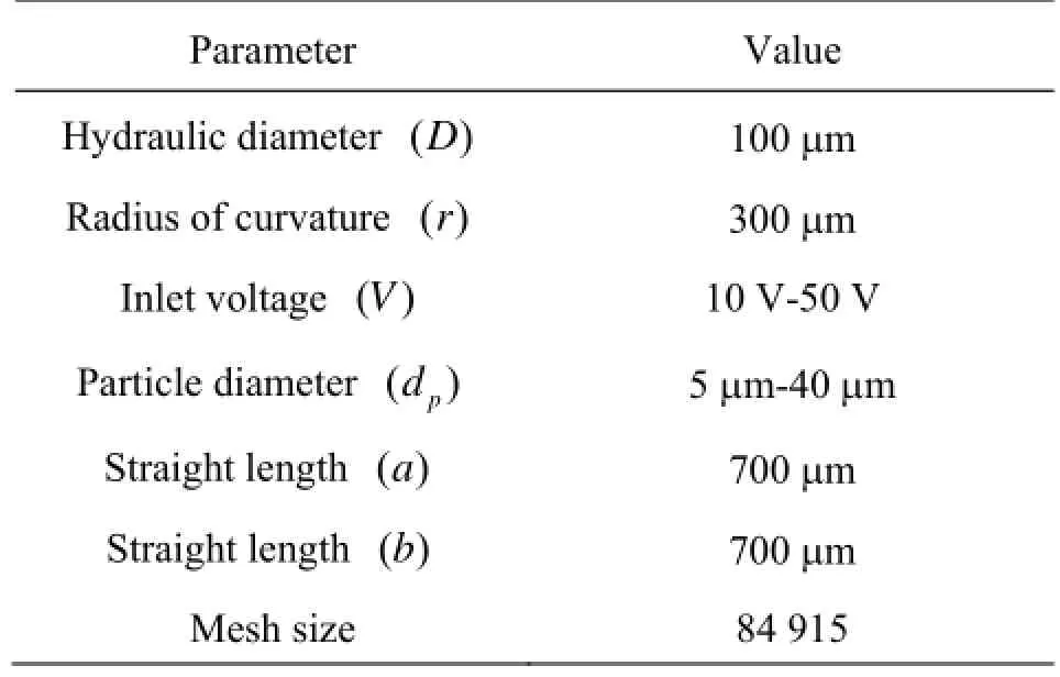
Table 1 Dimensions and details of the 90obend pipe
1.2 Fluid flow modelling
Assume that the flow is incompressible and steady, and the flow is driven by the electroosmosis, then the momentum equations of flow are given as

where V is velocity vector, p is pressure, ρ and μ denote the density and the viscosity of the solution, respectively, andeρ is the charge density. The relationship betweeneρ and the Electric Double Layer (EDL) potential φ is given as

where ε is the dielectric constant of the electrolyte solution, and0ε is the permittivity of vacuum, z isthe valence of ions, e is the fundamental electric charge, n∞is the ionic number concentration in the bulk solution, T is the absolute temperature of the solution, andbk is the Boltzmann constant.
The above equations use the following boundary conditions. For fluid flow, a constant pressure (atmospheric pressure) is specified at the inlet and outlet of the microchannel, no-slip boundary condition is imposed on the walls; for externally applied electric potential, a fixed value at the inlet and outlet is specified, and its normal-differential value on the wall is zero, for EDL potential, a fixed value on the wall is specified, and its normal-differential value on the inlet and outlet is zero. The control-volume-based method was used to solve these equations, and specified discretization method was used to get the secondary order accuracy. Equation (2) was solved firstly to get the distribution of surface potential and externally applied electric filed in the microchannel, and then Eq.(1) was solved to get the electrokinetic flow field.
1.3 Particle transport modelling
For a low volume fraction of dispersed phase (particles), the Lagrangian approach with one-way coupling was used, i.e., the fluid transports the particles, but the effect of particles movements on the flow was neglected. In this approach, the flow field was first simulated, and the trajectory of individual particle could be tracked by integrating a force balance equation on this particle, and the governing equation could be written as

which is taken from Haider and Levenspiel’s research. Here =1β for spherical particle.
Fgis the gravity term, which is defined as

where pρ and gρ denote the densities of particle and media, respectively.
The work described here involves the application of two electrokinetic forces that play a significant role in the induced motion of particles in liquid suspension. The dielectrophoretic forceDEPF exerted on a sphere for homogeneous body suspended in a local electric field gradient is expressed as

where rpis the particle radius, mpis the particle mass, εmis the permittivity of the suspending medium, ∇ is the gradient operator, E is the rms electric field, and Re[K(w)] is the real part of the Clausius-Mossotti factor that given by

where εm*and ε*pare the complex permittivities of the medium and particle, respectively, ε*=ε-jσ/w , where σ the conductivity, ε the permittivity, and w the angular frequency of the applied electric field. The limiting Direct Current (DC) case of Eq.(9) is

For a spherical particle of radius a and with surface charge, neglecting the polarization and the retardation effects under the thin EDL assumption, the electrophoretic forceEPF in an electric field E is given by

When fluid flow is forced to have a change in direction, such as in a bend, the large particles with high inertia are unable to follow the flow streamlines, and they will collide with the walls and deposit there, depending on the initial particle position at the bend inlet and other parameters such as the Stokes number andflow Reynolds number. On the other hand, the small particles with low inertia can follow the streamlines closely and penetrate through the bend.
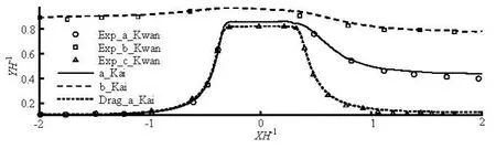
Fig.2 Individual 15.7 μm particle motion trajectory under =E20kV/m from the experimental and our computational results
When the particle moves close to channel wall, there exists a strong dielectric interaction between the particle and wall, resulting in a repulsive force. The magnitude of the repulsive force can be obtained by analyzing the local electric field around a particle close to a wall and integrating the Maxwell stress tensor on the particle surface. The fitted expression can be given as

Here γ is the distance between the wall and particle’s centroid. The forcewF is different from the EDL interaction which only occurs when the separation distance γ is in the order of nanometer.
In general, the particle transport and deposition in bends of circular cross section depends on five groups of dimensionless parameters

The Stokes number St is the most important parameter at low Reynolds number in microchannel flow and is defined as the ratio of the stopping distance of a particle to a characteristic dimension of the obstacle. For 1St≫, the particles will continue in a straight line as the fluid turns around the obstacle. For 1St≪, the particles will follow the fluid streamlines closely. τ is the relaxation time of the particle.cC is the slip correction factor, pρ the particle density, pd the particle diameter,0U the mean axial velocity in the bend, μ the fluid viscosity, D the tube diameter, v the fluid kinematic viscosity, and r the radius of curvature of the bend. In this model, St is varied from 1.0-6to 1.6×10⁻⁶, the particle Reynolds numberpRe is in the range of 0.00036-0.0029 for the Stokes flow cases, the Dean number De ranges from 0.03 to 0.15 with Ro=6.0, and the particle interception parameter NRranges from 0.005-0.04. The effect of Roon the particle transport and deposition has been shown to be insignificant.RN sometimes can be neglected since the particle diameterpd is usually several orders of magnitude smaller than the tube diameter D.
2. Validation
Exp._a_Kwan” and “a_Kai” represent the Kwan’s experimental results and our simulation results that account for the effect of drag/DEP/EP and repulsive force, respectively, “Drag_a_Kwan” and“Drag_a_Kai” represent the Kwan’s and our numerical results which only account for the drag force effect, respectively, “Exp._b_Kwan” and “b_Kai” represent the Kwan’s experimental results and our simulation results for the injection b that account for the DEP/EP and repulsive force effect, respectively.
The simulations in this paper were carried out by our in-house code. To validate our results, the trajectory of microparticle in the microchannel with rectangle-shaped hurdle in the middle was numerically calculated and compared with experimental and numerical results given by Kwan[4]. As is shown in Fig.2, it can be found that our computational results agree well with Kwan’s experimental and numerical results.
3. Results and discussion
To understand the regional particle deposition, the Deposition Efficiency (DE) for region i is defined as DEi=Nid/Ni0, where Ni0and Nidare the number of particles entering and depositing in the thi region, respectively. In addition, the mesh convergence and particle number independence tests were performed to ensure statistical independence. The number of cells outlined in Table 1 reflects that the discrepancy in velocity profiles is less than 1% when the mesh was further refined. The particle number of 20 000 could produce particle number independent simulationresults and hence was used for all simulation cases. Furthermore, it is assumed that water-liquid is used as the working fluid and its physical properties are givenPhysical properties of injected particles are given by
In the microchannel flow, the fluid is usually forced to change its direction in the bend. When the microparticles with different diameters are injected and tracked to the microchannel flow, it is difficult for particles with larger size to follow the flow streams due to the large hydrodynamic force. However, in the presence of electric field, the electrokinetic force (DEP and repulsive force) exerted on particle can change particle’s trajectory and hence increases DE obviously. To understand the effect of the above forces on the DE, the flow and electric field are discussed in detail.

Fig.3(a) The vector of the bend, and (b) contour of electric field (E) in the bend, and (c) direction of dielectrophoretic force (DEP) around the 90obend when the voltage drop is 10 V through the bend pipe
Figure 3 shows the electric field and the electrokinetic forces around the 90obend. As is shown in Fig.3(a), it can be found that the electric field is almost parallel to the axis of the bend. In addition, both the electroosmotic velocity of fluid and particle’s EP force are positively proportional to the electric field, and hence they have the same direction like the vector shown in Fig.3(a). From Fig.3(b), it can be noted that the intensity of electric field is greater in the inner bend and there exists large gradient, and it becomes weaker and almost homogenous in the straight part of the microchannel. Therefore, the microparticle passing the bend experiences stronger negative DC-DEP force in the bend, and it will depart from the inner wall.
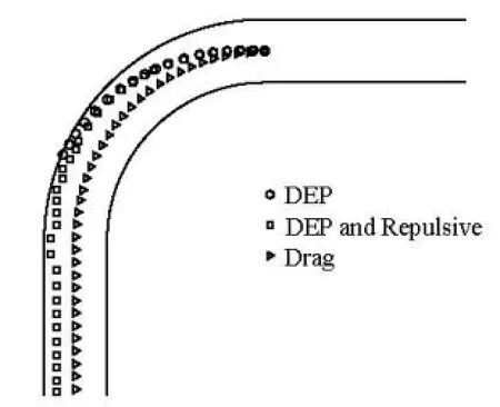
Fig.4 Trajectories of microparticle of diameter 20 μm injected from the axes of the bend with the applied potential difference of 50 V, experiencing only drag force (“▷”), both drag and DEP force (“○”), drag force, DEP force and repulsive force (“ ”), respectively
In general, when the particle is injected at the inlet of the bend pipe, its deposition is mostly induced by lateral displacement from the wall, and hence the DEP force affects the DE greatly and directly. The Stokes and EP forces will not directly influence microparticle’s DE in the bend, but they can change particle’s deposition position in the bend, as shown in Fig.4, since they can influence the acting time of DEP force on microparitlce. We can also find that when single particle is released from the axis of the bend, it will transport under those forces listed in Eq.(3). Among them, the Stokes force is induced by the relative velocity between the fluid and particle, because the fluid velocity is usually parallel to the axis of the bend pipe. Therefore, at the low Reynolds number and when only the Stokes force is exerted on the particle, the trajectory of microparticle is almost parallel to the wall of bend pipe. When the DEP force around the bend is considered, the moving microparticle in the bend will be repelled to the outer wall by the negative DEP force, and hence it is inclined to hit the outer bend and deposit there. When the DEP, repulsive force and drag forces are all considered, it can be found that the DEP force repels the particle to move close enough to the outer wall, but the repulsive force stimultaneously increase gradually, and finally there exists a balance between the DEP and repulsive force, and then the particle moves parallel to the wall of microchannel, which means that the DEP force can bring particle to the close region of outer wall straightly while the repulsive force will try its best to prevent the particle from being trapped by the wall.
When a large number of microparticles are released from the axis of the inlet of the bend, the number and position of microparticle deposited in the bend are recorded and shown in Fig.5(a) and Fig.5(c) under the action of different forces exerted on microparticle. Furthermore, the statistical method can be used to the get the contour of DE which is shown in Fig.5(b) and Fig.5(d), respectively. From Fig.5(a) and Fig.5(b),it can be seen that the microparticle transporting under the DEP andStokes force mostly deposit in the outer bend because of the repulsive effect of negative DEP force. The maximum deposition efficiency occurs in the middle of the outer bend, owing to the maximum DEP in its corresponding inner bend.
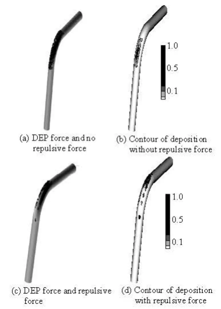
Fig.5 Regional deposition patterns of microparticles with diameter 20 μm and inlet voltage 50 V injected from inlet of the bend, and transport under drag force, DEP force and repulsive force

Fig.6 The fit of the microparticle deposition efficiency in the 90obend electrokinetic microchannel flow accounting for the DEP and hydrodynamic forces exerted on the microparticle
To obtain the unified theory of microparticle deposition efficiency in the 90obend, a large number of numerical simulations were carried out to study how the inlet voltage and particle diameter affect the DE, and the specified non-dimensional parameters are used to understand the comprehensive effect of those parameters on the microparticle DE. When the microparticle experiences the drag and DEP force in the fluid, the specified relationship between the microparticle DE and St can be well established. As is shown in Fig.6, it can be seen that the DE increases exponentially with the growth of St, and it reaches 1 and become steady when St is larger than 0.33×10⁻⁴, which means that it is very hard for the particle with larger St to follow the fluid flow, and it becomes inevitable to hit and deposit on the wall when St is larger than 0.33×10⁻⁴.

Fig.7 The fit of the deposition efficiency in the 90obend that accounts for the effect of the DEP, Stokes and repulsive forces
In general, the relationship between the St and its DE shown in Fig.6 can be given as

Here a, b and c represent constant coefficients, and χ represents the specified non-dimensional parameter (the particle Stokes number St or particle relaxation time τ), when the particle transports under the effect of DEP and hydrodynamic force, the fitted coefficient in Eq.(14) can be given as

The relationship between the DE of particle and its relaxation time τ under the effect of drag, DEP and repulsive force is shown in Fig.7. It can be seen that the DE increases exponentially with τ, and it reaches a steady value of 0.17 when τ is larger than 3.5×10⁻⁴. An exponential function like Eq.(14) is used to fit these numerical results, and the coefficients in that equation can be derived as

Figure 8 shows the comparison of particle DEamong three cases of different forces exerted on particle, the data marked with “o” shows that result based on Pui’s theory, which are concluded by considering only hydrodynamic force exerted on the particle, and it cannot be well used in the electrokinetic microchannel flow. In addition, if the DEP force and hydrodynamic force are considered, it is found that the DE increases quickly with the growth of particle St and DE can become 100% if St is larger than one critical value, and there exists the repulsive force which can stop the particle near the wall from being trapped by the wall. In general, the particle DE always increases with specified non-dimensional parameter gradually, and it can reach a steady value of DE eventually, while the specified relationships are different when the different forces are considered. In the practical condition, the microparticle DE mostly depends on its relaxation time. Obviously, the growth rate and steady value of DE under the DEP and Stokes force is larger than that under the DEP, Stokes and repulsive forces, and the corresponding value of ultimate DE is 1 and 0.17, respectively.
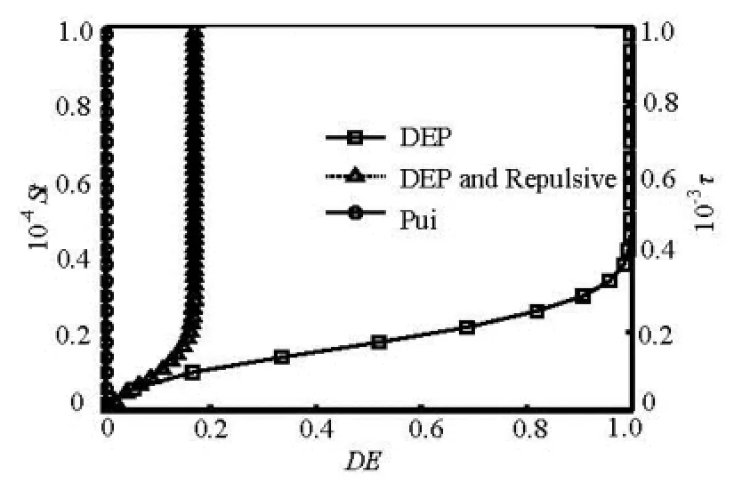
Fig.8 The relationship between the DE and St when (“ ”) DEP and hydrodynamic force, (“○”) only hydrodynamic force are considered, respectively; The relationship between the DE and τ when (“Δ”) DEP, hydrodynamic and repulsive force are considered
4. Conclusion
This study reports a theoretical and numerical investigation on the irreversible deposition of microparticles from electrokinetic microfluidic flow in a 90obend. The flow and electric fields are numerically simulated by the finite volume method first, and then a large number of microparticles are injected and traced with the one-way coupling Lagrangian model, incorporating the electrical, hydrodynamic, near-wall repulsive forces exerted on the microparticles. When drag force and DEP force are considered, it is found that the microparticles with larger size are repelled to close to the upper region of the outer wall. However, the near-wall repulsive force can prevent the particle from colliding with the wall and therefore decrease particle’s ultimate deposition efficiency. Furthermore, it is found that microparticle deposition efficiency has the specified exponential relationship with τ or St when the near-wall repulsive force is considered or not.
[1] WANG R., LIN J. Numerical analysis on a passive chaotic micromixer with helical microchannel[J]. Journal of Nanoscience and Nanotechnology, 2006, 6(1): 190-194.
[2] ROS A. D. R., HELLMICH J. and REGTMEIER J. et al. Bioanalysis in structured microfluidic systems[J]. Electrophoresis, 2006, 27(13): 2651-2658.
[3] KIM P., JEONG H. E. and KHADEMHOSSEINI A. et al. Fabrication of non-biofouling polyethylene glycol micro-and nanochannels by ultraviolet-assisted irreversible sealing[J]. Lab on a Chip, 2006, 6(11): 1432-1437.
[4] KWAN H. K., XUAN X. and YUEJUN K. et al. Effects of DC-dielectrophoretic force on particle trajectories in microchannels[J]. Journal of Applied Physical, 2006, 99(6): 064702.
[5] ZHENG L., BRODY J. P. and BURKE P. J. Electronic manipulation of DNA, proteins, and nanoparticles for potential circuit assembly[J]. Biosensors and Bioelectronics, 2004, 20(3): 606-619.
[6] SHAIKH F. A., UGAZ V. M. Collection, focusing and metering of DNA in microchannels using addressable electrode arrays for portable low-power bioanalysis[J]. Proceedings of the National Academy of Sciences, 2006, 103(13): 4825-4830.
[7] XIONG X., BUSNAINA A. and SELVAPRABA S. et al. Directed assembly of gold nanoparticle nanowires and networks for nanodevices[J]. Applied Physics Letters, 2007, 91(6): 063101.
[8] YU M. Z., LIN J. Z. and CHAN T. L. Effect of precursor loading on non-spherical TiO2nanoparticle synthesis in a diffusion flame reactor[J]. Chemical Engineering Science, 2008, 63(9): 2317-2329.
[9] WANG J., RICHARD C. and JOHN H. Seinfeld. Diffusional losses in particle sampling systems containing bends and elbows[J]. Journal of Aerosol Science, 2002, 33(6): 843-857.
[10] ZHANG Xiao-xi, CHENG Yong-guang. Simulation of hydraulic transients in hydropower systems using the 1-D-3-D coupling approach[J]. Journal of Hydrodynamics, 2012, 24(4): 595-604.
[11] HARIKRISHNAN N. U., CHUN Y. Colloidal particle deposition from electrokinetic flow in a microfluidic channel[J]. Electrophoresis, 2009, 30(5): 732-741.
[12] KANG Y., LI D. and KALAMS S. A. et al. DC-dielectrophoretic separation of biological cells by size[J]. Biomed Microdevices, 2008, 10(2): 243-249.
[13] IRENA B. N., XUAN X. C. and LEEA J. S. H. et al. DC-dielectrophoretic separation of microparticles using an oil droplet obstacle[J]. Lab on a Chip, 2006, 6(2): 274-279.
[14] YU M., LIN J. Taylor-expansion moment method for agglomerate coagulation due to Brownian motion in the entire size regime[J]. Journal of Aerosol Science, 2009, 40(6): 549-562.
[15] NIE D., LIN J. A fluctuating lattice-Boltzmann model for direct numerical simulation of particle Brownian motion[J]. Particuology, 2009, 7(6): 501-506.
10.1016/S1001-6058(11)60393-5
* Project supported by the National Natural Science Foundation of China (Grant No. 10902105), the Natural Science Foundation of Zhejiang Province (Grant No. 2010R10014).
Biography: ZHANG Kai (1979-), Male, Ph. D., Associate Professor
猜你喜欢
科教创新与实践(2022年1期)2022-04-20
方圆(2021年3期)2021-03-08
软件(2020年3期)2020-04-20
莫愁·智慧女性(2019年2期)2019-02-22
莫愁(2019年4期)2019-02-21
水动力学研究与进展 B辑(2018年3期)2018-07-06
中国检察官·经典案例(2016年12期)2017-01-14
——安徽省质监局稽查总队总队长张凯受贿案纪实
中国检察官(2016年24期)2016-02-11
水动力学研究与进展 B辑(2014年1期)2014-06-01
全国商情·分销时代(2013年12期)2014-03-26

- 水动力学研究与进展 B辑的其它文章
- Ship bow waves*
- Progress in numerical simulation of cavitating water jets*
- Three-dimensional large eddy simulation and vorticity analysis of unsteady cavitating flow around a twisted hydrofoil*
- Numerical simulation of shallow-water flooding using a two-dimensional finite volume model*
- Dynamical analysis of high-pressure supercritical carbon dioxide jet in well drilling*
- Simulation and analysis of ice processes in an artificial open channel*