
Flow characteristics of the two tandem wavy cylinders and drag reduction phenomenon*
2013-06-01 12:29ZOULin邹琳GUOCongbo郭丛波XIONGCan熊灿
水动力学研究与进展 B辑 2013年5期
ZOU Lin (邹琳), GUO Congbo (郭丛波), XIONG Can (熊灿)
School of Mechanical and Electronic Engineering, Wuhan University of Technology, Wuhan 430070, China, E-mail: l.zou@163.com
(Received February 27, 2013, Revised July 3, 2013)
Flow characteristics of the two tandem wavy cylinders and drag reduction phenomenon*
ZOU Lin (邹琳), GUO Congbo (郭丛波), XIONG Can (熊灿)
School of Mechanical and Electronic Engineering, Wuhan University of Technology, Wuhan 430070, China, E-mail: l.zou@163.com
(Received February 27, 2013, Revised July 3, 2013)
This paper presents an extensive numerical study of 3-D laminar flow around two wavy cylinders in the tandem arrangement for spacing ratios (L/Dm)ranging from 1.5 to 5.5 at a low Reynolds number of 100. The investigation focuses on the effects of spacing ratio (L/Dm)and wavy surface on the 3-D near wake flow patterns, the force and pressure coefficients and the vortex shedding frequency for the two tandem wavy cylinders. Flows around the two tandem circular cylinders are also obtained for comparison. With the spacing ratio in the range ofL/Dm=1.5-5.5, unlike two tandem circular cylinders, the wavy cylinders in the tandem arrangement do not have the wake interference behaviour of three basic types. The vortex shedding behind the upstream wavy cylinder occurs at a further downstream position as compared with that of the upstream circular cylinder. This leads to the weakening of the effect of the vibration of the cylinders as well as a distinct drag reduction. The effects of the drag reduction and the control of the vibration of the two wavy cylinders in tandem become more and more evident whenL/Dm≥4.0, with a distinct vortex shedding in the upstream cylinder regime for the two circular cylinders in tandem.
wavy cylinders, tandem arrangement, spacing ratio, drag reduction, vibration
Introduction
Flows past multiple cylindrical bodies are important in many engineering applications, for example, in the designs of cables, offshore structures, heat exchangers, high-rise buildings, and chimneys. The periodic vortex shedding and the fluctuating velocity fields behind the cylindrical bodies can cause structural damages, shorten the life of the structures and even lead to severe accidents. Hence, it is necessary to study the complicated flow around such multiple cylinders in order to improve the design of such equipment. The flow past cylindrical bodies, especially, that around one or two cylinders, has been extensively investigated. Williamson[1]and Wang[2]investigated the vortex dynamics of the wake behind a cylinder. For two circular cylinders in tandem arrangements, Lin et al.[3]and Deng et al.[4]investigated the near wake flow past two tandem circular cylinders and Jiang and Lin[5]studied the flows past two tandem cylinders of different diameters. These studies show that the flow around two tandem circular cylinders is sensitive to bothReand the spacing ratio (L/D). Zdravkovich[6]subdivided the flow patterns into three basic types based on the wake interference behaviour, Xu and Zhou[7]and Zhou and Yiu[8]also found the similar phenomenon, and a similar classification scheme was used by Carmo et al.[9,10], based on numerical simulations of two tandem circular cylinders. Sumner[11]reviewed the characteristics of two circular cylinders of equal diameter in a steady cross-flow.
It is a challenge to control the vortex-shedding phenomenon and hence to reduce the potential of flow-induced vibrations for the two cylinders in tandem arrangements. In order to suppress the associated bodies’ vibration, many experimental and numerical investigations were carried out over the past years. In recent few years, several types of cylinderswith a surface profile in sinusoidal curve along their spanwise direction, named the wavy cylinders, were introduced. The wavy cylinders can achieve the purpose of drag reduction and vibration damping at the same time. Lam et al.[12-15]investigated the control of force and bodies’ vibration of a wavy cylinder. They identified the optimal value of the spanwise wavelength (λ/Dm=6) for the drag force reduction and the fluctuating lift suppression atRe=100, and the maximum drag coefficient reduction can reach 18%, while the r.m.s. lift coefficient was equal to zero. Furthermore, they also found that a wavy cylinder with such a spanwise wavelength can provide a significant drag reduction and body vibration suppression for turbulent flows at subcritical Reynolds numbers from 6 800 to 13 400. Then they studied the threedimensional flow characteristics of such optimal wavy cylinder with yaw angles from 0oto 60o. Lam et al.[16]investigated turbulent flows around two fixed unyawed and yawed out-of-phase wavy cylinders in tandem arrangement at a subcritical Reynolds number of 3 900.
With regard to the investigations on the crossflow past two-tandem-cylinder arrays, most of the previous studies were focused on the effects of the spacing ratio on the two tandem circular cylinders. The effects of the spacing ratio of two-tandem-cylinder arrays and the wavy surfaces at the low Re have not yet been fully investigated. The understanding of the complex physical mechanism of 3-D flow characteristics around two wavy cylinders in the tandem configuration at lowReis still inadequate, as it is very difficult to gain this understanding by experimental measurements. The present investigation focuses on the effects of spacing ratio (L/Dm) and wavy surface on the 3-D instantaneous near wake flow patterns, force and pressure coefficients and vortex shedding frequency for the two tandem wavy cylinders of different spacing ratios atRe=100. The main objectives of the present work are to discover whether this type of wavy cylinder configurations with various spacing ratios at low Re can still suppress bodies’ vibration and reduce the drag force at the same time. In this paper, some valuable data, such as the drag, lift, the pressure, the velocity flied, the vortex shedding frequency and the flow pattern, are discussed in detail and compared with corresponding circular cylinders at the same arrangement. The physical mechanism of the drag reduction, as well as the influence of the upstream and downstream wavy cylinders will be studied. It is hoped that such an investigation will be helpful in engineering applications such as the vibrations of cables in suspension bridges and multiple risers in offshore engineering.

Fig.1 Geometric model of tandem wavy cylinders
1. Geometric of models
Figure 1 shows the geometric model of a wavy cylinder, the geometry of the wavy cylinders is described by the following equation
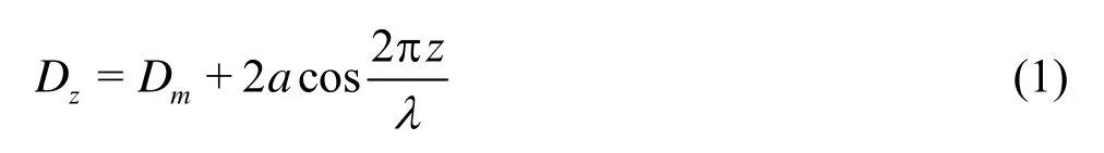
whereDzdenotes the local diameter of the wavy cylinder and varies in the spanwise directionz. The mean diameterDmis defined by
The amplitude of the wavy surfaceais equal to the half peak-to-peak distance. The axial location with the maximum local diameterDmaxis called the “node”, while the axial location of the minimum diameterDminis called the “saddle”. The “middle” is also defined at the midpoint position between the nodal and saddle planes. The diameter of the middle cross-section is equal to the mean diameterDm. In the present study, all geometrical lengths are normalized with the mean diameterDm. Furthermore, a circular cylinder with diameterDmis used for the comparison study.
2. Numerical method
2.1Governing equations
In the present study, the unsteady 3-D laminar flow of a viscous incompressible fluid is considered. The Finite Volume Method (FVM) with a structured hexahedral grid is employed to solve the unsteady 3-D incompressible Navier-Stokes equations.
The 3-D dimensionless Navier-Stokes equations governing the flow of a Newtonian fluid can be written in vector form as
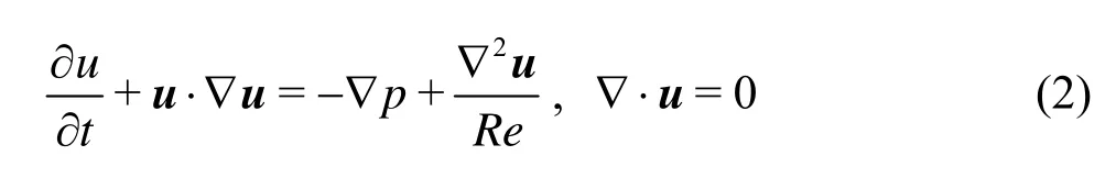
whereuis the non-dimensional flow velocity vector in the Cartesian coordinate system (x,y,z) with its three velocity componentsu,vandw.
The Semi-Implicit Pressure Linked Equations (SIMPLE) method is used to deal with the pressure velocity coupling between the momentum and the continuity equations. The second-order upwind differencing scheme is used for convective terms. The second-order central difference scheme is adopted for diffusion terms, while the second-order implicit scheme is employed to discretize the equations in time.
2.2Computational domain and boundary conditions
In the present study, the computational domain is a cube. Similar to the study of Lam et al.[13], the height (H) of computational domain is equal to one wavelength (H=λ=6Dm) in the spanwisez-direction. The upstream boundary of the computational domain is set at a distance of 12Dmfrom the centreline of the upper wavy cylinder, while the downstream boundary is 20Dmaway from the down wavy cylinder, and each lateral surface is 12Dmaway from the axis of the cylinder.
The boundary conditions are summarized as follows. At the inlet boundary, a uniform velocity profile is imposed. And the Neumann-type boundary condition is adopted at the outlet. The lateral surfaces are treated as slip surfaces, using the symmetry boundary conditions. Furthermore, at the boundaries in the spanwise direction, a periodic boundary condition is employed, and the no-slip boundary condition is prescribed at the surface of the wavy cylinders.
Similar grid distributions are used in the present simulations (see Fig.2), based on the previous simulation models on the flow past a single wavy cylinder[13]. Figure 2 shows the detailed diagram of the grid system. In thex-yplane, the unstructured hexahedral grids are non-uniform with 120 grid points uniformly distributed along the circumferential direction of each cylinder, while 56 uniform layers of cells are used in the spanwise direction along thez-direction.
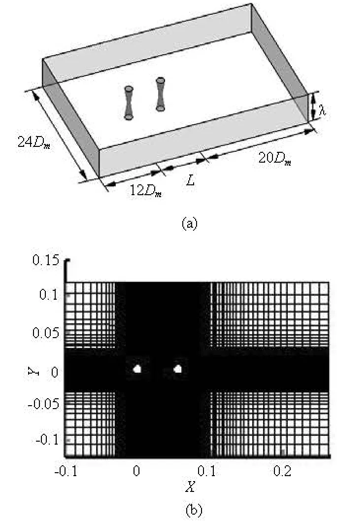
Fig.2 Computational domain and grid distribution
Details of the grid independence tests and the validation of the numerical models are listed in Table 1. Because of many available numerical simulations and experimental researches on circular cylinders, the grid independence tests on circular cylinders are made. As shown in Table 1, the difference of the results between coarse and fine grid distributions of circular cylinders is not significant. The results of wavy cylinders are also very good. So the coarser grid distribution model is adopted in the present simulations on the flow past two cylinders to save computing time.
3. Results and discussions
3.1Flow patterns
The flow patterns and the near weak vortex structures around the cylinders show a strong relationship with the instantaneous pressure distribution and the force characteristics. Hence, in order to have a better understanding of the characteristics of the pressure and the force on the cylinders, it is very important to have a clear picture of the effect ofL/Dmon the vortex structures around the cylinders. The vortex shedding frequency characteristics of the cylinder, represented by Strouh al numberSt=fDm/Um, w her e the vortexsheddingfrequencyfisobtainedbyFastFourier Transform of the cylinder’s fluctuating lifttime history, is also obtained for revealing the relationship between the vortex shedding frequency and the wake structure.
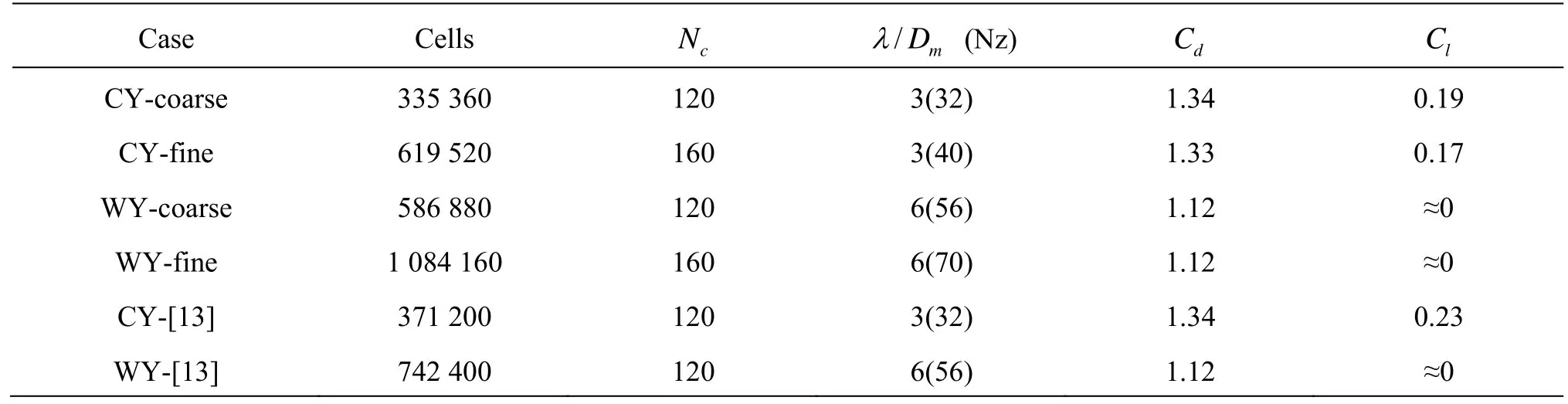
Table 1 Grid independence test of a circular and wavy cylinder atRe=100
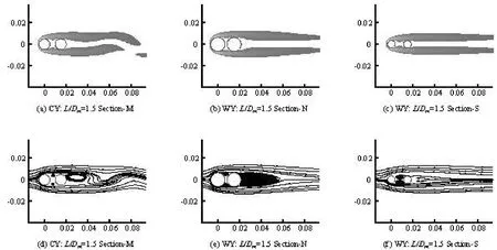
Fig.3 Instantaneous spanwise vortices and time averaged streamline distributions of circular or wavy cylinders atL/Dm=1.5 in thex-yplane. CY: circular cylinder, WY: wavy cylinder
The characteristics of the flow past the two tandem wavy cylinders at low Reynolds numbers are the focus of the present study. As is well known, the flow around two tandem circular cylinders is sensitive to bothReandL/Dm, and the spacing ratio between the cylinders has a strong effect on the flow pattern around the downstream cylinder. The pioneering studies of the tandem configuration by Zdravkovich[6]identified three basic types of wake interference behaviour: (1) single bluff-body behaviour, also referred to as the ‘‘extended-body regime’’ by Xu and Zhou[7]and Zhou and Yiu[8], at small /mL D, where the two cylinders are sufficiently close to each other to act as if a single structure, (2) shear layer reattachment behaviour, also referred to as the ‘‘reattachment regime’’by Xu and Zhou[7]and Zhou and Yiu[8], at intermediateL/Dm, where the separated free shear layers from the upstream cylinder reattach onto the surface of the downstream cylinder and vortices may form in the gap between the cylinders. The reattachment regime can be subdivided into two basic flow regimes based on the Strouhal number[7]and the wake flow structure and the vortex dynamics[8], (3) Karman vortex shedding from each cylinder, also referred as the‘‘co-shedding regime’’ by Xu and Zhou[7]and Zhou and Yiu[8], at large /mL D.
Figure 3 shows the typical instantaneous spanwise vortices and the time averaged stream line distributions for two circular cylinders and two wavy cylinders in tandem arrangements at a small center-to-
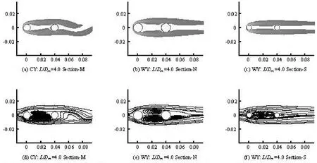
Fig.4 Instantaneous spanwise vortices and time averaged streamline distributions of circular or wavy cylinders atL/Dm=4.0 in thex-yplane

Fig.5 Instantaneous spanwise vortices and time averaged streamline distributions of circular or wavy cylinders atL/Dm=5.5 inx-yplanes
center spacing ratio ofL/Dm=1.5. For circular cylinders with such smaller spacing ratio ofL/Dm=1.5, as would be expected, the whole downstream cylinder is almost in the recirculation zone of the upstream cylinder and no reattachment happens to the downstream cylinder and the two bodies behave like a single lengthened bluff body with vortex formation far behind the downstream cylinder. And the free shear layers look symmetrical, named the symmetric in the gap (SG) flow pattern by Carmo et al.[9,10], between the cylinders. The downstream cylinder, in some respects, can be considered to behave in a manner similar to a short splitter plate[8]. As a result, the value ofStis less than the corresponding single cylinder case (Stis close to 0.1279 for tandem cylinders, whileStis close to 0.16 for a single circular cylinder). For wavy cylinders withL/Dm=1.5, similar flow patterns can also be observed but without vortex formation behind the downstream wavy cylinder. The downstream wavy cylinder is fully enveloped by the free shear layers from the upstream cylinder and the free shear layers never roll up into small vortices be-hind the downstream wavy cylinder. On the contrary, the free shear layer behind the downstream wavy cylinder looks symmetrical. Because of the symmetrical flow pattern and the fact that no shedding occurs, the Strouhal number of the tandem wavy cylinders is close to zero.
Increasing the spacing ratio toL/Dm=4.0, as shown in Fig.4, two symmetrical unstable free shear layers from the upstream circular cylinder can be observed in the space between the two tandem circular cylinders and it was named as the AG (alternating in the gap) flow pattern by Carmo et al.[9,10]. The free shear layers of the upstream cylinder roll up into vortices and reattachment in front of the downstream circular cylinder surface in addition to a more regular vortex shedding formed behind the downstream circular cylinder. But no mature alternative vortex shedding occurs behind the upstream circular cylinder. Such a flow pattern indicates thatL/Dm=4.0 is in the critical spacing ratio regime for two tandem circular cylinders. This result agrees with the results obtained by Alam et al.[17]and Sharman et al.[18]. But for tandem wavy cylinders withL/Dm=4.0, unlike circular cylinders, the free shear layers from the upstream wavy cylinder are still symmetrical and stable, and there is no regular vortex shedding formed behind the downstream wavy cylinder. The two tandem wavy cylinders also behave like a single lengthened bluff body, as is observed at the smaller spacing ratio.
When the spacing ratioL/Dmcontinues to increase, reaching such a large spacing ratio asL/Dm= 5.5, as shown in Fig.5, the downstream circular cylinder leaves the recirculation zone of the upstream one gradually and the interaction between two circular cylinders becomes weaker. It was named as the wake in the gap (WG) flow pattern by Carmo et al.[9,10]. There is an ample spacing between the tandem circular cylinders for the development of a mature wake vortex behind the upstream circular cylinder, as a result, the two circular cylinders now act as two isolated cylinders but they interact with each other further downstream. While, for the two tandem wavy cylinders at the spacing ratio ofL/Dm=5.5, there is no mature wake vortex formed between the tandem wavy cylinders. The downstream wavy cylinder is still in the recirculation zone of the upstream cylinder and the two bodies behave like a single lengthened bluff body, as shown in Fig.5. The free shear layers behind the downstream wavy cylinder are still very stable.
Figure 6 shows the time averaged streamlines distributions for wavy cylinders atL/Dm=12.0 and 13.0 in thex-yplane. It can be seen that atL/Dm= 12.0, the streamlines between the tandem wavy cylinders are not distorted, that is to say, no mature wake vortex between the upstream and downstream cylinders. But one can see that the free shear layers have already attached on the front face of the downstream cylinder. IncreasingL/Dmto 13.0, the streamlines are found distorted significantly. That means that there are mature wake vortices behind the upstream wavy cylinder and the vortex begin to impact on the downstream cylinder.
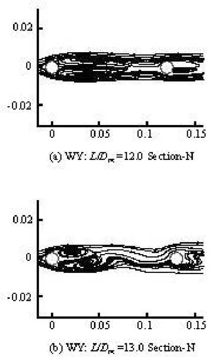
Fig.6 Instantaneous spanwise vortices and time averaged streamline distributions of wavy cylinders atL/Dm=12.0 and 13.0 inx-yplanes
3.2Strouhal numbers and shedding frequencies
The Strouhal numbersSt=fDm/Unhave a close relationship with the flow patterns around the tandem cylinders and the power spectra of the fluctuating lift.
Figures 7 show the power spectra of the fluctuating lift and the Strouhal numbers of both the tandem circular and wavy cylinders withL/Dmin the range from 1.5 to 5.5. One can see that the power spectra of the fluctuating lift of the wavy cylinders have no obvious peak point as in the case of the circular cylinders. Typically for the upstream wavy cylinder at the spacing ofL/Dm=1.5, a very low Strouhal number of 0.0009 is obtained for the upstream wavy cylinder due to the effect of the additional oncoming flow motion on the wavy surface of the wavy cylinder in the spanwise direction. And due to the smaller spacing ofL/Dm=1.5, as shown in Fig.3, the vortex shedding from the upstream cylinder is inhibited by the downstream cylinder. So the value of St is less than those in the corresponding single cylinder case, which is consistent with the result of Lam et al.[16]for tandem wavy cylinders in turbulent flows. The valueofStfor the upstream and downstream circular cylinders, at the same spacing ratio, is almost the same. IncreasingL/Dmto 4.0, because of the reattachment of the free shear layers of the upstream circular cylinder on the downstream circular cylinder, the value ofStfor the upstream circular cylinder is less than that for the circular cylinder atL/Dm=1.5. Further increasing the spacing ratio to 5.5, the Strouhal number of the upstream circular cylinder increases significantly and goes close to the value for the single cylinder. This also explains the fact that the tandem circular cylinders behave like a single cylinder at a large spacing ratio. In the meantime, the Strouhal number for the upstream wavy cylinder has no obvious change. This is just consistent with the characteristics of the flow pattern for the tandem wavy cylinders. It should be noted that for the circular cylinders atL/Dm=5.5 with two power spectral peaks, only the main peak values of the shedding frequencies which play the major role on the vortex shedding are plotted for comparison.
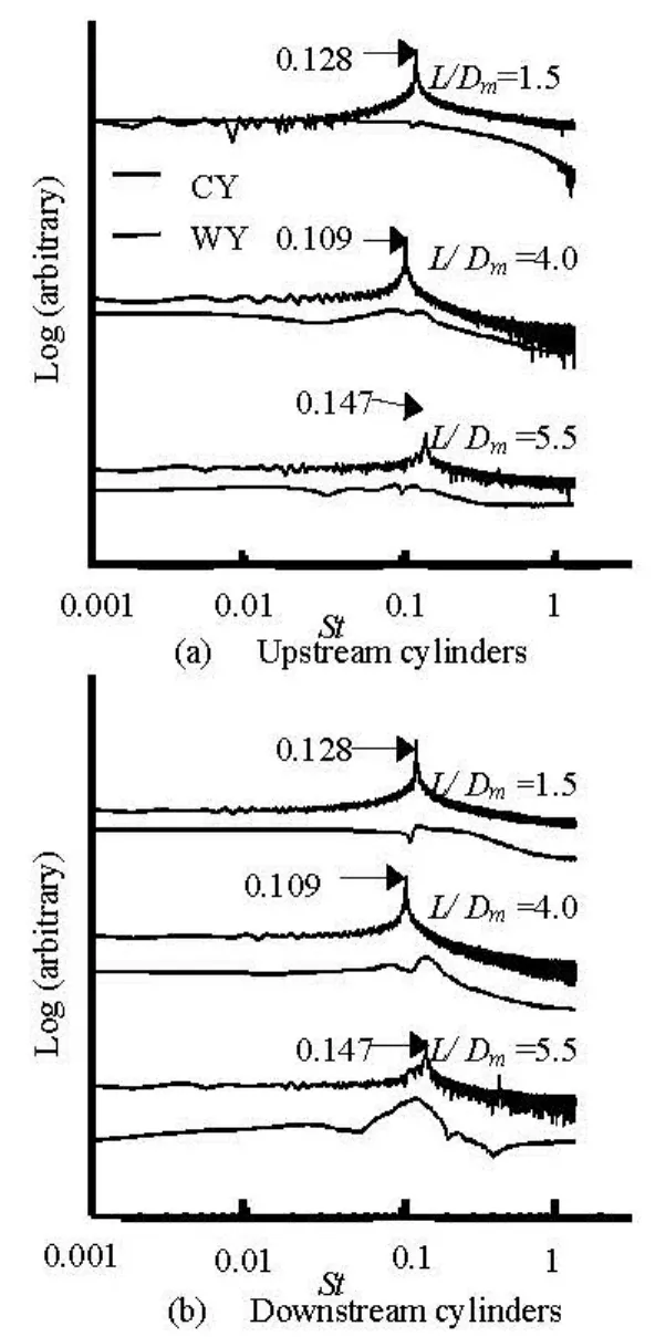
Fig.7 Power spectra of fluctuating lift of the circular and wavy cylinders
3.3Pressure characteristics
The pressure coefficient on the cylinder surface is defined asCP=2(p-p∞)/(ρU?), wherepis the circumferential static pressure on the cylinders andp∞is the oncoming flow static pressure.CPis the time-averaged mean pressure coefficient andCp′ is the time-averaged fluctuating pressure coefficients (root-mean-square value rms). Figure 8 shows the distributions of the time-averaged mean pressure coefficients and the time-averaged fluctuating pressure coefficients in the middle section of the circular cylinders (section-M) and in two different sections of the wavy cylinders (section-N and section-S) atL/Dm=1.5. For the upstream cylinder, it can be seen that the difference in the pressure coefficientsCpandCp′ around the cylinder is not significant. This may imply that there is no significant drag reduction and suppression of the cylinder’s vibration for the upstream wavy cylinder[12]. While, for the downstream cylinder, very little variation ofCpandCp′ can be observed since the upstream free shear layers have wholly enveloped the downstream one. And the value ofCp′ for the downstream circular cylinder is slightly larger than that for the wavy cylinder, due to the vortex formed far behind the downstream circular cylinder, as shown in Fig.3.
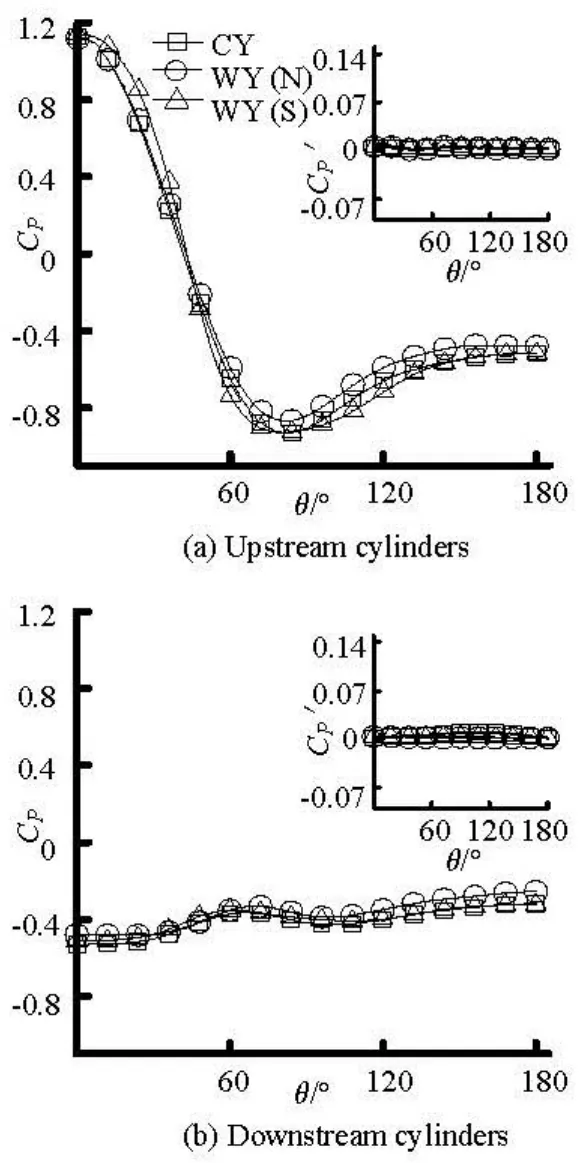
Fig.8 Pressure distributions on the cylinder surfaces atL/Dm=1.5. CY (M): circular cylinder in section-M, WY(N): wavy cylinder in section-N, WY(S): wavy cylinder in section-S
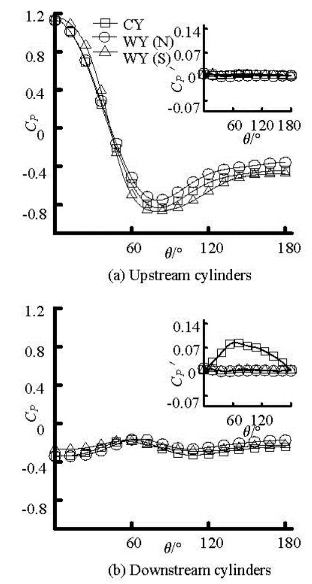
Fig.9 Pressure distributions on the cylinder surfaces atL/Dm=4.0
Figure 9 shows the distributions of the circumferential mean pressure coefficientCpand the fluctuating pressure coefficientCp′ for the cylinders at the critical spacing regime ofL/Dm=4.0. There is negligible difference in the mean pressure coefficientsCparound the upstream cylinder and the fluctuating pressure coefficientaround the downstream cylinder. For the upstream wavy cylinder, the base pressure coefficient (Cpatθ=180o) at section-N is greater than that of the corresponding upstream circular cylinder. This means that the drag force on the upstream wavy cylinders is smaller than that of the upstream circular cylinders[12]. The differences in the back pressure coefficients for the circular and wavy cylinders of the upstream cylinders would result in reduction of the drag force for the upstream wavy cylinders. For the downstream circular cylinder, a peak value?is observed at θ slightly over 60o. This is the result of the upstream free shear layers impinging on the downstream circular cylinder at that position. The peak in′ distribution occurs at or very near the separation point of the shear layer in the case of a laminar separation. Due to the vortex shedding forming behind the downstream circular cylinder, which can be seen in Fig.4,′ on the surface of the downstream circular cylinder is larger than the corresponding downstream wavy cylinder. The phenomena mentioned above also indicate that the spacing ratioL/Dm=4.0 is the critical spacing for tandem circular cylinders.
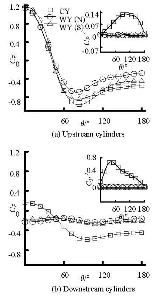
Fig10 Pressure distributions on the cylinder surfaces atL/Dm=5.5
The distributions of the mean pressure coefficientCpand the fluctuating pressure coefficient′ for the tandem cylinders with a large spacing ratio ofL/Dm=5.5 are shown in Fig.10. It can be seen that, unlike tandem wavy cylinders, the distributions ofCpand′ are similar to those for a single cylinder at the same flow conditions for both the upstream and downstream circular cylinders. The flow patterns for the two tandem circular cylinders also show that they act as two isolated cylinders at such a spacing ratio. And a significant reduction of the drag force as well as the suppression of fluctuating lift occur for the tandem wavy cylinders because of the evident differences in the back pressure coefficients and the fluctuating pressure coefficient′. Owing to the continuous impingement of the mature upstream vortices on the downstream cylinder, a peak value offor the downstream circular cylinder can be seen atθaround 45o.
3.4Force characteristics
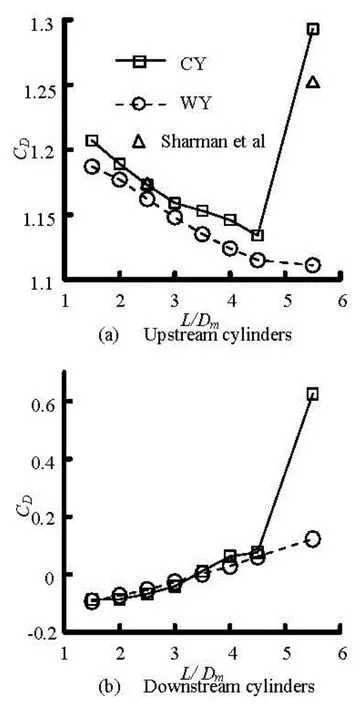
Fig.11 Mean drag coefficients
The three definitions for the different flow patterns and the time-averaged circumferential pressure distributions of the cylinders are consistent with the force characteristics on the cylinders. In the present calculations, the drag coefficientCDand the lift coefficientCLare defined asCD=2FD/(ρUDmλ) andCL=2FL/(ρUDmλ), respectively, whereρis the fluid density,FDandFLare the total drag force and the total lift force. The mean drag coefficients() of both wavy and circular cylinders with various spacing ratiosL/Dmare shown in Fig.11.of the upstream wavy cylinders is slightly smaller than that of the upstream circular cylinders at spacing ratioL/Dm<4 because of the similar flow patterns and pressure coefficient distributions. For the large spacing ratioL/Dm=5.5, owing to the mature wake vortex behind the upstream circular cylinder,of the upstream circular cylinder is significantly larger than that of the wavy cylinder. Howeverof the downstream wavy cylinder takes a slightly higher value than that of the corresponding circular cylinder at spacing ratioL/Dm<4. This is partly due to the effect of the reattachment free shear layers from the upstream wavy cylinder to the downstream wavy cylinder in section-S. The lowerof the downstream cylinder indicates that the downstream cylinder is completely shielded by the upstream cylinder when the spacing is within the critical spacing ratio. Because of the mature wake vortex formed behind the upstream circular cylinder impinging on the downstream circular,CDof the downstream cylinder assumes a significant rising.
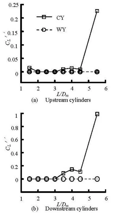
Fig.12 Fluctuating lift coefficients (rms value)
Figure 12 shows the fluctuating lift coefficient′ (rms value) for the tandem cylinders. For both upstream and downstream wavy cylinders, owing to the symmetrical and stable flow patterns, the fluctuating lift coefficientare close to 0 at different spacing ratios. While for circular cylinders, because of the mature wake vortex formed behind the upstream cylinder, there is a significant jump at the spacing ratioL/Dm=5.5. All these results confirm that the wavy cylinders (λ/Dm=6 anda/Dm=0.15) are a suitable choice for drag reduction and vibration suppression control for multiple cylinder structures in the laminar flow condition. And such beneficial effect is gradually evident with the increasing spacing ratioL/Dmof the cylinders.
4. Conclusion
In the present investigations, the laminar flows around two wavy cylinders (λ/Dm=6 anda/Dm= 0.15) in the tandem arrangement with a constant Reynolds number of 100 are calculated through the three-dimensional numerical simulations based on the finite volume method. And in this paper, some valuable data, such as the drag, the lift, the pressure, the velocity field, the vortex shedding frequency and theflow pattern, are discussed in detail in comparison with a corresponding circular cylinder at the same arrangement. The force coefficients obtained by the three-dimensional numerical simulations show good agreement with the experimental measurements and other published results. It is found that, unlike the quite quasi-two-dimensional flow pattern of the circular cylinders’ wake vortex structures, the wake vortices of the wavy cylinders show a periodic repetition along the spanwise direction. Compared with the tandem circular cylinders atL/Dm=1.5-5.5, the tandem wavy cylinders behave like a single lengthened bluff body without showing the so-called three basic flow patterns. The flow patterns of the tandem wavy cylinders show a very symmetrical and stable distribution until the spacing ratio is increased toL/Dm=12.0. The critical spacing ratio for the transition from the narrow gap flow pattern to the vortex impingement flow pattern around the circular cylinders is found to beL/Dm=4.0. WhenL/Dm<4.0, owing to the similar flow patterns and pressure coefficient distributions, the effect of the drag reduction as well as the suppression of the fluctuating lift for the tandem wavy cylinders is not significant as compared with circular cylinders. WhileL/Dm>4.0, which is when the flow pattern transits to the vortex impingement for circular cylinders, a significant reduction of the drag force as well as the suppression of the fluctuating lift can be seen for the tandem wavy cylinders atRe= 100.
[1] WILLIAMSON C. H. K. Vortex dynamics in the cylinder wake[J]. Annual Review of Fluid Mechanics, 1996, 28: 477-539..
[2] WANG Jia-song. Flow around a circular cylinder using a finite-volume TVD scheme based on a vector transformation approach[J]. Journal of Hydrodynamics, 2010, 22(2): 221-228.
[3] LIN J. C., YANG Y. and ROCKWELL D. Flow past two cylinders in tandem: Instantaneous and averaged flow structure[J]. Journal of Fluids and Structures, 2002, 16(8): 1059-1071.
[4] DENG Jian, REN An-lu and ZOU Jian-feng. Three-dimensional flow around two tandem circular cylinders with various spacings atRe=200[J]. Journal of Hydrodynamics, Ser. B, 2006, 18(1): 48-54.
[5] JIANG Ren-jie, LIN Jian-zhong. Wall effects on flows past two tandem cylinders of different diameters[J]. Journal of Hydrodynamics, 2012, 24(1): 1-10.
[6] ZDRAVKOVICH M. M. The effects of interference between circular cylinders in cross flow[J]. Journal of Fluids and Structures, 1987, 1(2): 239-261.
[7] XU G., ZHOU Y. Strouhal numbers in the wake of two inline cylinders[J]. Experiments in Fluids, 2004, 37(2): 248-256.
[8] ZHOU Y., YIU M. W. Flow structure, momentum and heat transport in a two-tandem-cylinder wake[J]. Journal of Fluid Mechanics, 2006, 548: 17-48.
[9] CARMO B. S., MENEGHINI J. R. and SHERWIN S. J. Possible states in the flow around two circular cylinders in tandem with separations in the vicinity of the drag inversion spacing[J]. Physics of Fluids, 2010, 22(5): 054101.
[10] CARMO B. S., MENEGHINI J. R. and SHERWIN S. J. Secondary instabilities in the flow around two circular cylinders in tandem[J]. Journal of Fluid Mechanics, 2010, 644: 395-431.
[11] SUMNER D. Two circular cylinders in cross-flow: A review[J]. Journal of Fluids and Structures, 2010, 26(6): 849-899.
[12] LAM K., LIN Y. F. Large eddy simulation of flow around wavy cylinders at a subcritical Reynolds number[J]. International Journal of Heat and Fluid Flow, 2008, 29(4): 1071-1088.
[13] LAM K., LIN Y. F. Effects of wavelength and amplitude of a wavy cylinder in cross-flow at low Reynolds numbers[J]. Journal of Fluid Mechanics, 2009, 620: 195-220.
[14] LAM K., LIN Y. F. and ZOU L. et al. Experimental study and large eddy simulation of turbulent flow around tube bundles composed of wavy and circular cylinders[J]. International Journal of Heat and Fluid Flow, 2010, 31(1): 32-44.
[15] LAM K., LIN Y. F. and ZOU L. et al. Investigation of turbulent flow past a yawed wavy cylinder[J]. Journal of Fluids and Structures, 2010, 26(7-8): 1078-1097.
[16] LAM K., LIN Y. F. and ZOU L. et al. Numerical simulation of flows around two unyawed and yawed wavy cylinders in tandem arrangement[J]. Journal of Fluids and Structures, 2012, 28(1): 135-151.
[17] ALAM M. M., MORIYA M. and TAKAI K. et al. Fluctuating fluid forces acting on two circular cylinders in a tandem arrangement at a subcritical Reynolds number[J]. Journal of Wind Engineering and Industrial Aerodynamics, 2003, 91(1-2): 139-154.
[18] SHARMAN B., LIEN F. S. and DAVIDSON L. et al. Numerical predictions of low Reynolds number flows over two tandem circular cylinders[J]. International Journal for Numerical Methods in Fluids, 2005, 47(5): 423-447.
10.1016/S1001-6058(13)60420-5
* Project supported by the National Natural Science Foundation of China (Grant No. 11172220).
Biography: ZOU Lin (1970-), Female, Ph. D., Associate Professor

- 水动力学研究与进展 B辑的其它文章
- A one-dimensional polynomial chaos method in CFD–Based uncertainty quantification for ship hydrodynamic performance*
- Numerical analysis of cavitation within slanted axial-flow pump*
- Numerical simulation of hydro-elastic problems with smoothed particle hydrodynamics method*
- Analytic solutions of the interstitial fluid flow models*
- Experimental study of shell side flow-induced vibration of conical spiral tube bundle*
- A streamline approach for identification of the flowing and stagnant zones for five-spot well patterns in low permeability reservoirs*