
Directive Emission Derived from A Meta-surface with Complete Bandgap of Surface Resonances
2013-07-25 06:37CAOYangLIUYuanyunYUXingWUBinghengGUHaoFENGHongquanLIHongqiang
发光学报 2013年12期
CAO Yang ,LIU Yuan-yun,YU Xing,WU Bing-heng,GU Hao,FENG Hong-quan,LI Hong-qiang
(1.Shanghai Radio Equipment Institute,Shanghai 200090,China;2.Shanghai Key Laboratory of Electromagnetic Environmental Effects for Aerospace Vehicle,Shanghai 200090,China;3.School of Physics Science and Engineering,Tongji University,Shanghai 200092,China)*Corresponding Author,E-mail:caoyang85@163.com
1 Introduction
Structured metal surfaces support electromagnetic surface modes bound to the metal/dielectric interface,giving rise to remarkable optical phenomena including extraordinary optical transmission(EOT)through subwavelength hole arrays[1-6].These modes are called surface plasmon polaritons(SPPs)[7]at visible and near-infrared frequencies,and characterized by strongly enhanced local field at the interface.In the microwave regime,metals can be treated as plasmon-free perfect conductors.However,with the assistance of localized surface resonances,a structured perfect metal surface can support mimicking surface plasmons and design artificial ones with almost arbitrary dispersion in frequency and in space[8-10]. With these plasmon-like local resonances,there still exists EOT in terahertz[11]and microwave region[12].
Surface mode bandgap engineering is very crucial to light manipulation by plasmonic materials and metamaterials.It has been recently reported that a metal plate perforated with a triangular array of air holes possesses complete bandgap of surface resonances and presents beam collimation effect in a certain frequency range covering the bandgap[13].As the complete surface resonances bandgap suppresses any surface resonances with nonzero in-plane wave vectors,it can be utilized to design directional antennas.
In this paper,we theoretically and experimentally investigate the microwave EOT through a thin aluminum plate perforated with a triangular array of air holes.Modal expansion method(MEM)[14-16]is employed to calculate the transmission spectra under plane wave incidence and extract the dispersion of surface resonances on the meta-surface.A complete bandgap is found at 10.20 ~10.94 GHz for all polarizations and all in-plane wave vectors.It is verified by parametric study of holes size that the triangular lattice is predominant to the formation of the complete bandgap.A dipole antenna positioned near the meta-surface radiates directionally at low band edge and other frequencies within the bandgap,which can be applied to realize a new kind of surface wave antenna with high directivity.
2 Model Description
As shown in Fig.1(a),the sample is fabricated on an aluminum plate with a thickness oft=2 mm and a lateral size of 1 000 mm×1 000 mm.The lattice constant of the triangular array isp=30 mm.The diameter of holes isd=15 mm.The front surface of the sample plate and the irreducible Brillouin zone of the triangular lattice are schematically illustrated in Fig.1(b)and Fig.1(c).
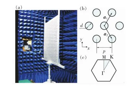
Fig.1 Schematic of the model system.(a)A photo of the experimental setup.(b)The front surface of the sample plate.(c)The irreducible Brillouin zone of the triangular lattice.
Angle-dependent transmission spectra and radiation patterns are measured in microwave chamber with Agilent 8722ES network analyzer.The sample plate is on a rotary table which is controlled by computer with a finest angular resolution of 0.1°.
3 Complete Bandgap ofSurface Resonances
Transmission spectra under different incident angles are calculated by MEM.Fig.2 shows the dispersion of surface resonances extracted from transmission spectra by tracing the peak frequencies as a function of in-plane wave vector[1].The even-mode surface resonances are marked by circular dots,while the odd-mode surface resonances are represented by gray dashed lines.It is noted that the evenmode surface resonances possess abandgap at 10.20 ~11.52 GHz for TM polarization,which fully covers the TE polarization bandgap at 10.20 ~10.94 GHz.Thus the complete bandgap for all polarizations and all in-plane wave vectors has a width of 740 MHz,which is marked by the shadowed region in Fig.2.
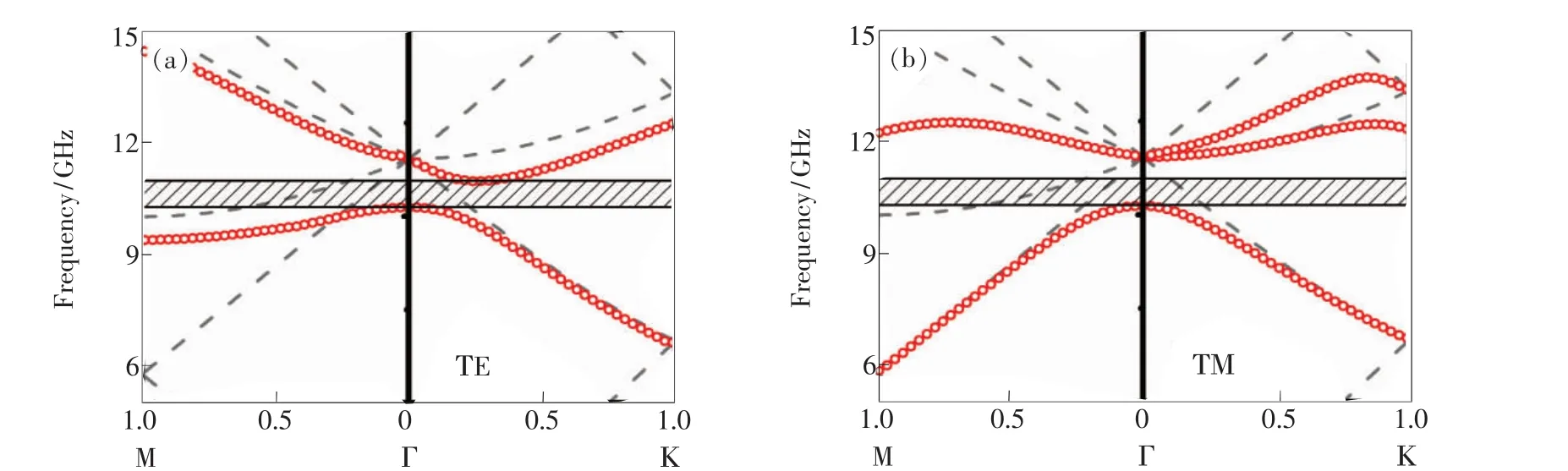
Fig.2 Dispersion diagrams for TE(a)and TM(b)polarized surface resonances for the sample with a triangular array in evenmode(circular dots)and odd-mode(dashed lines).The complete bandgap is marked by the shadowed region.
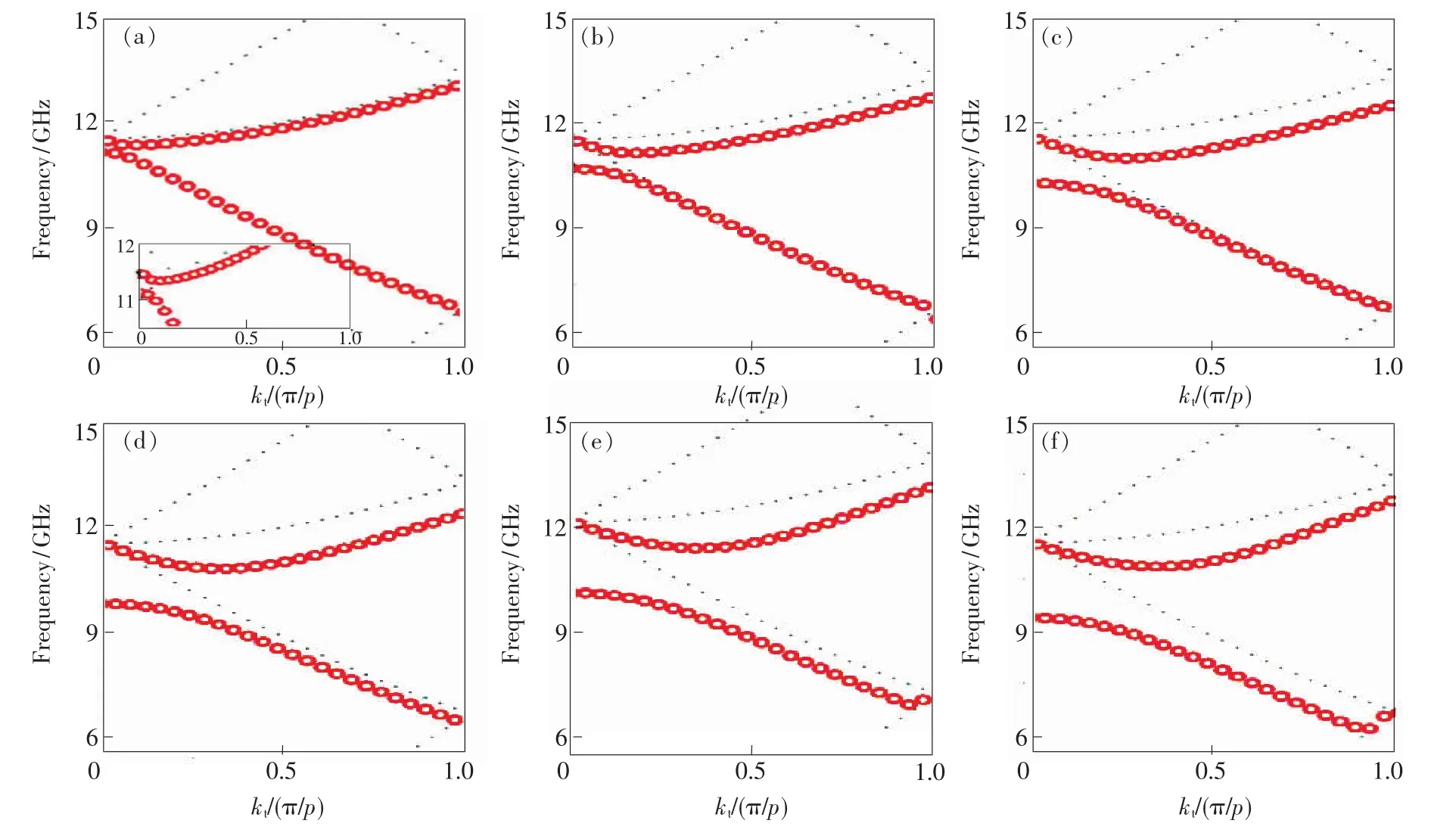
Fig.3 Dispersion diagrams for TE polarized surface resonances along ΓΚ direction for different holes size.(a)d=11 mm.(b)d=13 mm.(c)d=15 mm.(d)d=17 mm.(e)d=19 mm.(f)d=21 mm.
4 Directive Emission from The Meta-surface
To demonstrate the directive emission from the meta-surface,we adopt a dipole antenna working at 10 GHz for the measurements.It is positioned along thexdirection and 2 mm apart from the surface of perforated aluminum plate.
Directive emission is attainable within the frequency range of 10.20 ~ 10.94 GHz inside the bandgap.The measured half power bandwidths are 5.6°inE-plane and 6.2°inH-plane with an optimal return loss about-10 dB at the lower band edge 10.20 GHz.Blue and green circular dots in Fig.4 present the measured polar charts at 10.20 GHz.For verification,we perform FDTD simulations to calculate the radiation patterns from a dipole close to a model plate with a lateral size of 300 mm×260 mm.The calculated half power bandwidths are 6.8°inE-plane and 7.1°inH-plane,shown as red and black lines in Fig.4,which coincide with the measurements.
5 Conclusion
In summary,we find that a complete bandgap of surface resonances exists on a meta-surface arranged with a triangular array of air holes.It is proved that the triangular lattice is predominant to the formation of the complete bandgap,and the bandgap always exists during the variation of holes size.Directive emission from a dipole antenna positioned near the meta-surface,with half power beamwidth of 5.6°inE-plane and 6.2°inH-plane,is observed in the complete bandgap.The findings are helpful in realizing beam collimator and high directive antennas with ultra thin structure.
[1]Ebbesen T W,Lezec H J,Ghaemi H F,et al.Extraordinary optical transmission through sub-wavelength hole arrays[J].Nature,1998,391(6668):667-669.
[2]Ghaemi H F,Thio T,Grupp D E,et al.Surface plasmons enhance optical transmission through subwavelength holes[J].Phys.Rev.B,1998,58(11):6779-6782.
[3]Martin-Moreno L,Garcia-Vidal F J,Lezec H J,et al.Theory of extraordinary optical transmission through subwavelength hole arrays[J].Phys.Rev.Lett.,2001,86(6):1114-1117.
[4]Liu J,Chen B X,Yang H M.Ion-exchange single-mode stripe waveguide for excitation of surface plasma wave[J].Opt.Precision Eng.(光学 精密工程),2011,19(10):2342-2348(in Chinese).
[5]Gay G,Alloschery O,De Lesegno B V,et al.The optical response of nanostructured surfaces and the composite diffracted evanescent wave model[J].Nat.Phys.,2006,2(4):262-267.
[6]Li W,Wang G Z,Yang F,et al.3-D finite element simulation for measurement of micro-torque of dental implant by SAW devices[J].Opt.Precision Eng.(光学 精密工程),2013,21(7):1713-1718(in Chinese).
[7]Raether H.Surface Plasmons on Smooth and Rough Surfaces and on Gratings[M].Berlin:Springer-Verlag,1988.
[8]Pendry J B,Martin-Moreno L,Garcia-Vidal F J.Mimicking surface plasmons with structured surfaces[J].Science,2004,305(5685):847-848.
[9]De Abajo F J G,Saenz J J.Electromagnetic surface modes in structured perfect-conductor surfaces[J].Phys.Rev.Lett.,2005,95(23):233901-1-4.
[10]Hibbins A P,Evans B R,Sambles J R.Experimental verification of designer surface plasmons[J].Science,2005,308(5722):670-672.
[11]Qu D X,Grischkowsky D,Zhang W L.Terahertz transmission properties of thin,subwavelength metallic hole arrays[J].Opt.Lett.,2004,29(8):896-898.
[12]Beruete M,Sorolla M,Campillo I,et al.Enhanced millimeter-wave transmission through subwavelength hole arrays[J].Opt.Lett.,2004,29(21):2500-2502.
[13]Cao Y,Wei Z Y,Wu C,et al.Collimation effect inside complete bandgap of electromagnetic surface resonance states on a metal plate perforated with a triangular array of air holes[J].Opt.Exp.,2012,20(23):25520-25529.
[14]Sheng P,Stepleman R S,Sanda P N.Exact eigenfunctions for square-wave gratings:Application to diffraction and surfaceplasmon calculations[J].Phys.Rev.B,1982,26(6):2907-2916.
[15]Lalanne P,Hugonin J P,Astilean S,et al.One-mode model and Airy-like formulae for one-dimensional metallic gratings[J].J.Opt.A:Pure Appl.Opt.,2000,2(1):48-51.
[16]Wei Z,Fu J,Cao Y,et al.The impact of local resonance on the enhanced transmission and dispersion of surface resonances[J].Photon.Nanostruct.,2010,8(2):94-101.
猜你喜欢
初中生学习指导·中考版(2022年4期)2022-05-12
中学生数理化(高中版.高考理化)(2021年5期)2021-07-16
太空探索(2016年6期)2016-07-10
中国照明(2016年5期)2016-06-15
合成化学(2015年9期)2016-01-17
筑路机械与施工机械化(2015年11期)2015-07-01
筑路机械与施工机械化(2015年8期)2015-01-11
航天返回与遥感(2014年1期)2014-07-31
筑路机械与施工机械化(2014年4期)2014-03-01
筑路机械与施工机械化(2014年3期)2014-03-01
- 发光学报的其它文章
- 《发光学报》入选“2012年中国国际影响力优秀学术期刊”