
Ice accretion simulation in supercooled large droplets regime
2013-11-08 06:17BAIJunqiangLIXinHUAJunWANGKun
空气动力学学报 2013年6期
BAI Jun-qiang,LI Xin,HUA Jun,2,WANG Kun
(1.College of Aeronautics,Northwestern Polytechnical University,Xi’an 710072,China;2.Chinese Aeronautical Establishment,Beijing 100012,China)
0 Introduction
Aircraft aerodynamic surfaces are subject to ice accretion when flying through clouds of supercooled water droplets,ice accretion on the wing or on the tail wing can lead to serious degradation of the aerodynamic performance,such as an increase in drag,a decrease in the stall angle,altered moment characteristics of the aircraft and a decrease in lift.More importantly,ice accretion on propellers or engine nacelles can cause dangerous accident when the ice accretion breaks free.Traditionally,the design of de-icing and anti-icing systems is based on the impingement limits corresponding to Mean Volumetric Diameters(MVD)of 40μm or less,which is currently defined in Appendix C of the Federal Aviation Regulation(FAR)25regulations.SLD (MVD>40μm)induce severe icing conditions,cause water film run back on longer distances and freeze beyond the areas protected by the anti-icing system,when the de-icing system is activated,the dangerous ridge ice accretion can occur on the wing behind the leading edge de-icing system.In fact,in two relatively recent aircraft accidents (ATR-72commuter at Roselawn,IN,in 1994and Embraer-120twin turboprop at Detroit in 1997)the primary cause has been attributed to ice ridges due to SLD[1]. A research program on aircraft in-flight icing conducted byMeteorological Service of Canada out of St.John’s and Ottawa showed that SLD occurred 41%of the time during in-flight icing conditions experienced near Ottawa and 73%near St.John’s,so these dangerous conditions are quite frequent[2].
It is very clear that the design of anti-icing and de-icing system based on theMVDof 40μm is insufficient,and an extension of numerical approach to account for SLD effects is needed.The problem is such an extension is difficult for the SLD regime violates some assumptions made by Bourgault et al[3].The first one is SLD do not travel at the freestream velocity because of their largeMVDs,SLD no longer enjoy a stable velocity,so an additional velocity component needs to be introduced in the initial velocity.The second one is SLD are prone to deform under the influence of shear forces,resulting in an oblate disk shapes.The last one is the splashing and rebound effects may lead to partial deposition of the impinging droplet mass.
Many researchers have done lots of work to take into account the effects of terminal velocity,droplet deformation,splashing and rebound.One of the detailed experimental studies was performed by Stow who reported on the impact of water drops on a dry surface[4].Khan and Richardson derived an expression to take into account the effects of terminal droplet velocity[5].Yarin and Weiss proposed a splashing model as a type of kinematic discontinuity[6].Bai and Gosman did a lot of work on rebound model[7].In china,many people have done research on numerical simulation of ice accretion,such as Yi Xian,Wei Dong,Wang Jiangfeng et al[8-10],but few people did research related to SLD regimes,Jianping Hu and Zhenxia Liu did a research on SLD impact behaviors on Aero-engine Strut in 2011[11].
In this study,an Eulerian droplet tracking method together with models for splashing and rebound are described.First of all,the splashing and rebound model calibration is needed.A recent study performed by Papadakis facilitates the calibration of the model[12].The experiment was carried on a NACA23012airfoil of 1.8288span over a large range of droplet diameters,MVDof 111μm was employed to conduct the calibration work.To examine the accuracy of the model,the splashing model was then used along with the rebound model to generate ice shapes on a NACA0012airfoil,the dataset chosen was reported by Potapczuk in 2003[13].To establish the model’s applicability to arbitrary geometries,flow conditions and droplet size distributions,a three-element airfoil consists of a slat,a main element and a flap was chosen to evaluate the effects of SLD on the impingement results and predicted ice accretion[14-15].
1 Formulation and numerical method
1.1 Governing equations for gas phase
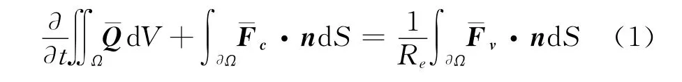
The flow field for air can be obtained by solving the Reynolds-Averaged Navier-Stokes (N-S)equations.Numerical approach is based on the finite volume form of the integral equations.In a domain of a volumeΩwith boundary∂Ω,the equation can be written in the integral form:
The vector of the conserved variables,the convective flux term,and the viscous flux term are given as follows,respectively.

The Cell-centered finite volume method is employed to solve the N-S equations,and the Lower-Upper Symmetric Gauss-Siedel (LU-SGS)algorithm for time marching,Roe Flux Difference Splitting scheme for the spatial discretization of the convective flux is implemented into codes.The treatment of the far field boundary condition is based on the introduction of Riemann invariants for a one dimensional flow normal to the boundary.Chi andShih[16]suggested that Spalart-Allmaras (S-A)is proper for simulating ice accretion.The N-S equations are closed by the S-A model with thermally perfect gas and temperature-dependent properties,see details in Reference[17].
1.2 Governing equations for droplets
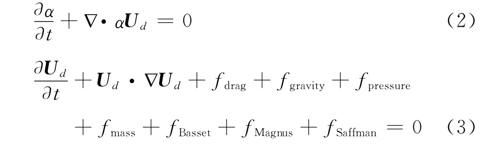
The continuity equation and momentum equations for droplets are a set of partial differential equations,one of the source terms for the momentum balance will have to be the drag force,since it is the main force for the droplet phase.The equations for mass and momentum conservation of the droplet phase are[18-19]:
The other source term considered besides the drag forcefdragare gravity force,pressure gradient force,mass force,Basset history force,Magnus force and Saffman force.
The drag fore is modeled using the drag coefficientCD:
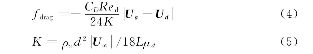
WhereRedis the droplets Reynolds number,Kis an inertia parameter,Lis reference length,dis the droplet diameter,ρw,U∞,μddenote the density of water,freestream velocity and molecular viscosity coefficient respectively.
Droplets having large diameter are prone to deform under the influence of shear forces,resulting in the increase in aerodynamic drag at SLD conditions[20]:
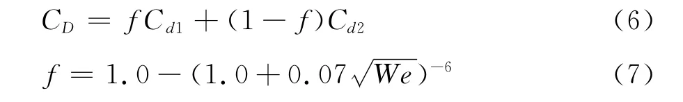
Weber number is:

Cd1andCd2represent the drag coefficients of a spherical particle and oblate disk,respectively.σdis the droplet surface tension.
The force due to gravity and buoyancy is:
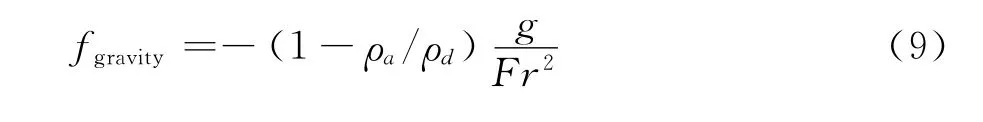
Froude number is expressed as[21]:

The Saffman force describes a lift force for small particles,it is more important for small particles than for the larger particles that are being studied.The Basset force models the effect of the change in drag as a function of time which is used to model the flow of gas bubbles,this effect is unimportant for present study,since the viscosity of air is much less than that of droplets.Saffman and Basset forces can be safely ignored based on calculation in LEWICE.For large droplets with big inertia,Magnus force is negligible.The ratio of mass force to the drag force,is of the order of 10-4in icing conditions,since ice accretion involves no shock wave,so the pressure gradient force can be neglected reasonably.
The finite volume method is applied to discretize the governing equations,the convective term is discretized using the QUICK(Quadratic Upwind Interpolation of Convective Kinematics)scheme,and the deferred correction method is used to ensure the diagonal dominance in the discretized equations.In order to guarantee the stability of the iterative solution of algebraic equations,the source term is disposed linearly,the Alternating Direction Implicit(ADI)iteration method is utilized to solve the algebraic equations.In the Eulerian method,the setting of the wall boundary condition is very important in the calculation of collection efficiency,apermeable wall boundary condition is applied to simulate the droplets’impingement onto the wall[22].
2 SLD model
2.1 Terminal velocity of droplets
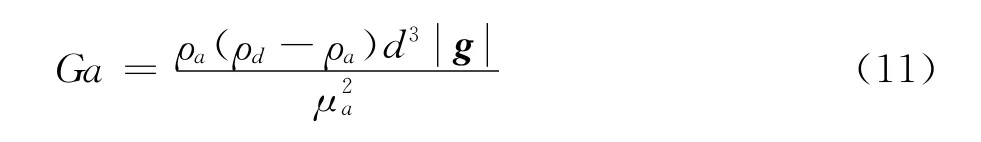
Khan and Richardson used a dimensionless Galileo number defined as a function of physical properties of the droplet and gas phase to account for the terminal velocity[5],
Terminal Reynolds number is:

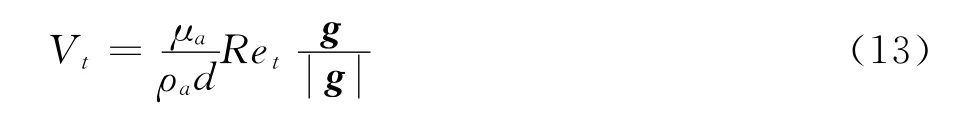
The corresponding terminal velocity can be obtained from terminal Reynolds number:
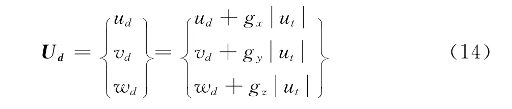
Once the terminal velocity corresponding to a givenMVDis determined,the initial velocity may be changed accordingly(three dimensional case):
2.2 Interactions between droplet and ice accreting surface
Bai and Gosman collected a number of results from literature and tried to identify some threshold levels in terms of dimensionless numbers for impact phenomenon[7].They proposed several mechanisms of wall-droplet interactions,four of them within the operational envelope of in-flight icing,Weber number and Laplace number dominate the behaviors of droplets when impact occurs(Fig.1 ),
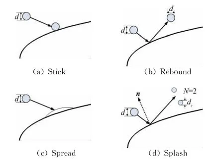
Fig.1 Schematic of droplet-wall interaction mechanisms图1 水滴和物面相互作用示意图
Stick,We<2
Rebound,2<We<10
Spread,10<We<1320La-0.183
Splash,We>1320La-0.183
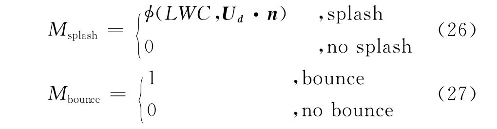
Stick and spread have no mass loss,so they are accounted for automatically in governing equations,rebound and splashing mechanisms are required to incorporate into droplet governing equations.
The model for mass-loss due to splashing in SLD conditions by Honsek is used[23],the mass-loss coefficient is expressed as:
Kywis defined by Yarin and Weiss[6]:

With the Ohnesorge number defined as:
Trujillo determined the number of secondary droplets after splashing,the following relation for the number of secondary droplets[24]is introduced:
Kdryis a function of the non-dimensional surface roughnessksnd,

Cosali number[25]is similar tokyw:

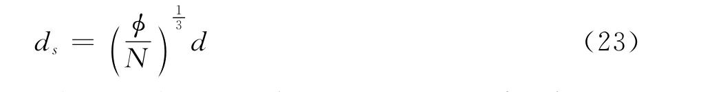
When splashing occurs,the normal and tangential components of secondary droplet velocities are determined by functions based on the experimental data reported by Mundo[26],
The average size of secondary droplets can be determined by:
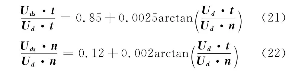
About rebound,the components of velocities follow the expressions below:
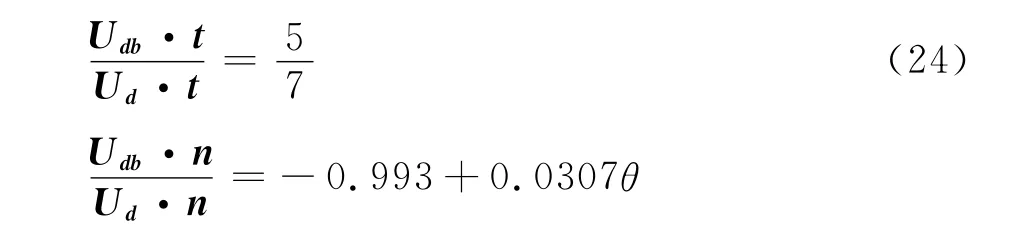

Whereθ=90-arctan
For an Eulerian method,the splashing and rebound phenomenon cause mass loss,this phenomenon is implemented by defining a splashing boundary condition and a rebound boundary condition,which means adding a source term to the flux in the mass and momentum equations at the wall boundary,the source terms for mass equation are:
The source terms for momentum equations are:
With source termsMandIincluded,the following droplet governing equations are obtained:
Wherei=1,2,…,Nbinindicates the droplet bin.
3 Collection efficiency
The collection efficiency shows the distribution of liquid on ice accreting surface,with the solution of droplet volume fraction,α,and the distribution of velocity,the collection efficiencyβcan be obtained with the following expression:
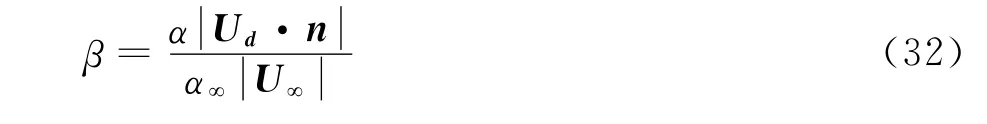
Wherenis unit vector normal to wall,U∞andα∞are the velocity and the droplet volume fraction of far field.
4 Icing model
The icing model is based on the model proposed by Messinger[27],the icing model consists of mass and energy conservation equations,for each control volume,the conservation equation of droplet mass can be described as follows,
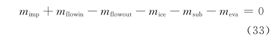
Wheremimpis the flux of impinging droplets,mflowinis the total mass flux entering the control volume from the previous control volume,mflowoutis the total mass flux flow out of the control volume,miceis ice accumulation in the control volume,msubis the flux due to ice sublimation in control volume,mevais the flux caused by water evaporation in control volume under consideration.
The improved thermal conservation equation can be expressed as the following,
WhereQcondis conductive heat through the ice accreting surface,Qimpis the heat carried by impinging droplets,Qevais the heat transfer induced by water evaporation,Qiceis the freezing heat stored in accreted ice,Qconvis convective heat,Qairis aerodynamic heating by airflow,Qsubis heat transfer caused by ice sublimation,Qflowinis the heat added into the present control volume from previous control volume,Qflowoutis the heat transfer out of the control volume,further information may be found in Reference[28].
5 Results
5.1 Model calibration with NACA23012
Papadakis performed experiment with differentMVDsfor a NACA23012airfoil at angle of attack equals to 2.5°,one case ofMVDequals 111μm was selected to carry on the calibration work,the selected case and the corresponding conditions are shown in table 1 .In order to get more accurate results,droplet size distribution of LangmuirDis employed for selected case.The splashing and rebound model mentioned above are implemented into present code,it is easier for Eulerian method to implement re-injection phenomenon than Lagrangian method does.The catching efficiency with splashing and rebound effects is compared with the catching efficiencywithout the effects as well as experimental results.The catching efficiency calculated is shown in Fig.2,a dramatic improvement is observed when the SLD model is employed.Due to the SLD effects,the catching efficiency decreases almost everywhere,especially near the impingement limitation as shown in Fig.2.It should be noted that over-predicted decrease occurs near leading edge and impingement limitation.Anyway,close agreement with experimental data can be obtained by taking into account the SLD effects.
Table 1 Test conditions for model calibration表1 模型验证计算条件
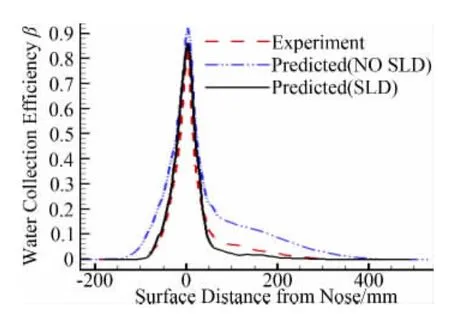
Fig.2 Water collection efficiency of NACA23012图2 NACA23012翼型水滴收集率
The Liquid Water Content(LWC)can be obtained easily since the full field of the droplets can be provided by Eulerian method,the calculatedLWCfor selected case is shown in Fig.3,for this case,there is apparent difference in theLWCwith and without SLD effects,especially near the leading edge,showing a region of increasedLWCconcentration.The reason for this is once the splashing effect occurs near leading edge,the splashed secondary droplets are re-injected into a smaller bin corresponding to the diameter closest to the secondary droplet diameter obtained from the splashing model.
From the above discussion,the proposed mathematical model may be considered mathematically consistent and physically representative.
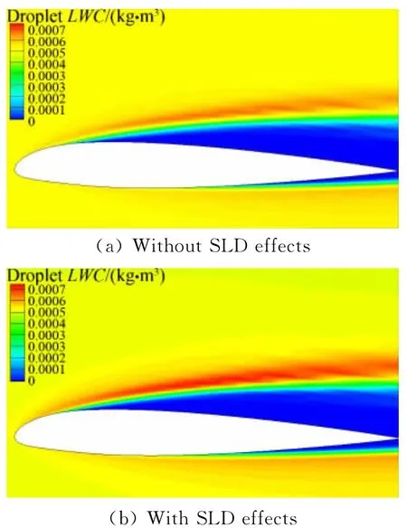
Fig.3 Liquid water content distribution of NACA23012图3 NACA23012翼型液态水含量分布云图
5.2 Ice accretion on NACA0012
The splashing model is then used along with the rebound model to generate ice shape on a NACA0012airfoil,the selected case is Run 1-23which was reported by Potapczuk[13],the calculate conditions are shown in table 2 .The same as NACA23012,Langmuir D distribution is used here.The comparison shows a slight decrease in the overall shape when the splashing model is activated,as illustrated in Fig.4 d,the calculation captures the overall size and shape of the experimental ice shape,whereas the calculation is unable to reproduce the detail of the ice shape surface nor is it able to depict the small structures aft of the main ice shape.The using of the SLD model decreases the amount of ice accretion almost everywhere,especially near the aft limits of the ice shape.
For the calculated ice shape,corresponding water collection efficiency is shown in Fig.4 c,collection efficiency decreases after accounting for SLD effects,especially near icing limit whereas unapparent decrease near leading edge.Since breakup occurs only in regions of high velocity gradient,so splashing phenomenon dominates near the leadingedge,while rebound phenomenon dominates near the icing limit.This explains why catching efficiency decreases more severely near icing limit,for the mass-loss coefficient equals to 1when rebound occurs,when it comes to splashing,the mass-loss coefficient is less than 1.
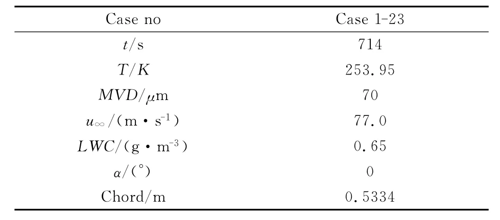
Table 2 Parameters for ice accretion on NACA0012表2 NACA0012冰形预测计算条件
Fig.4 The results of Case 1-23图4 算例Case 1-23结果
Fig.4 bshows theLWCdistributions for the SLD effects around the airfoil,near the suction and pressure side of the airfoil,there are two symmetry shadow zones in which droplet volume fraction nearly equals to zero,the calculation with SLD effects have smaller shadow zone than the calculation without SLD effects.Particularly,SLD effects which are the splashed and rebounded phenomenon due to the droplet-wall interaction are observed as a result ofLWCdistributions,Fig.4 bdemonstrates that SLD effects tend to enhance theLWCconcentration around the airfoil.
5.3 Ice accretion on three-element airfoil
In this section,a high lift airfoil section is selected to address the needs of large transport aircraft,it is an advance high lift system which designed in the early 1990′s.The three element airfoil consists of a slat,a main element and a flap with 36 inches chord.For this case,only the landing configuration is considered in this investigation,for the landing configuration the slat deflection is 30°leading edge down and the flap deflection is 30°trailing edge down,the definition of deflection of the highlift components is set with respect to the main element wing reference plane.The gap and overlap are defined to depict the slot size between the main element and the high lift components.Gap is the minimum distance between the leading edge of the downstream element and the trailing edge of the upstream element,for the flap,the gap is 0.457inches and for the slat it is 1.062inches.Overlap is the horizontal distance from the leading edge of the downstream element and the trailing edge of the upstream element,the overlaps for the flap and slat are 0.09 and-0.9inches respectively.Test parameters are in table 3,the temperature for the ice accretion is 260.65K,LangmuirDdistribution is used to computethe overall impingement distribution.
Table 3 Parameters for ice accretion on three-element airfoil表3 三段翼冰形预测计算条件
Fig.5 Three-element high lift system图5 三段翼示意图
TheLWCdistribution and water collection efficiency are shown in Fig.6 and Fig.7 respectively,around the airfoil,some shadow zones appear near the pressure side of the slat and flap,the suction side and the trapped vortex area of the main element.Droplets splashing,rebound and re-impingement had relatively greater effects on the flap element compared to the slat and main element,for concentration zones(Fig.6 b)are observed near the leading edge of the flap and the pressure side of the three-element airfoil,which are thought to be contributed by the splashed droplets.As shown in Fig.7,all elements experience significant mass loss due to droplet splashing and rebound process,which means SLD effects can not be ignored.Fig.7 also shows that accounting for SLD effects has resulted in a better agreement with the experimental impingement distributions for all the elements,especially for slat and flap elements.The collection efficiency near the trailing edge of the flap is over-predicted slightly while an under-prediction collection efficiency is found in the main element,this is very likely due to the sensitivity of the droplet rebound model and splashing model that resulted in the mass flux being over or underestimated for the models have not been validated quantitatively.
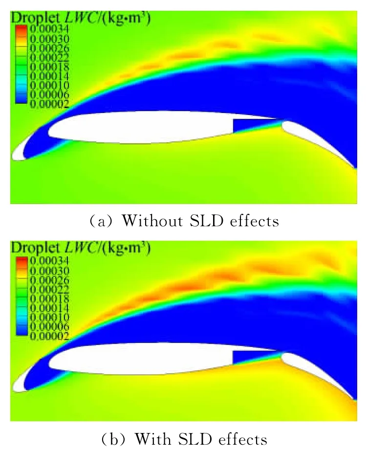
Fig.6 Liquid water content distribution图6 三段翼液态水含量分布云图
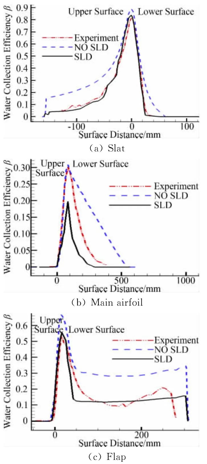
Fig.7 Water collection efficiency图7 三段翼水滴收集率
For the icing shape calculated from the catching efficiency with and without SLD effects,shown in Fig.8,a decrease of the ice thickness can be observed downstream of the leading edge compared with that of without SLD effects.For all the elements,there are significant changes when compared to those calculated without SLD effects,so the SLD effects can not be negligible.
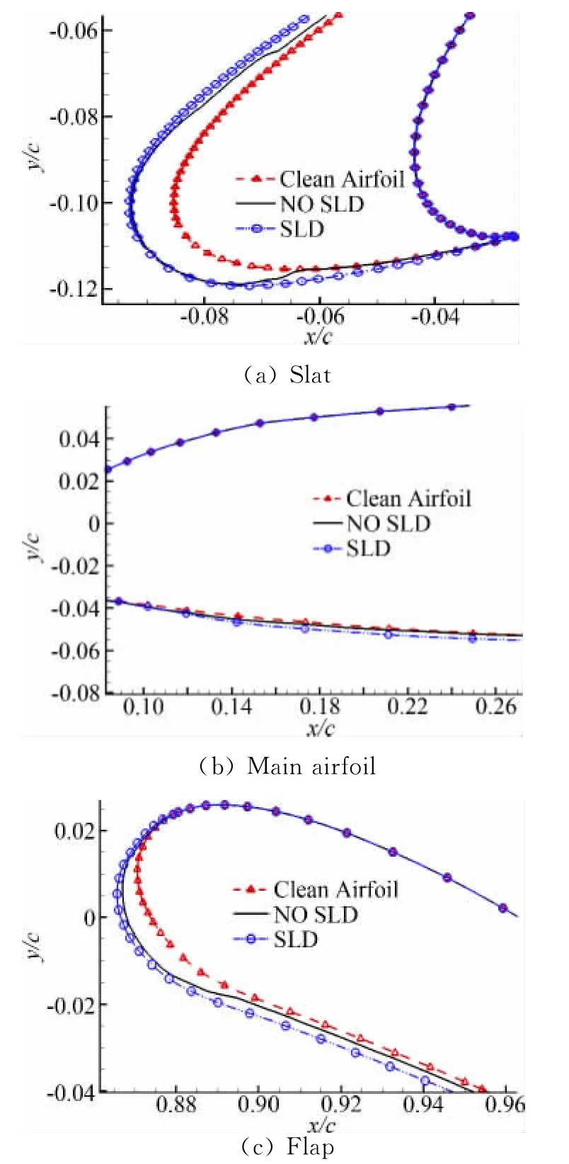
Fig.8 Predicted ice shape图8 冰形预测结果
6 Conclusion
A suitable mathematical model for the dropletwall interactions in an Eulerian method has been proposed and successfully calibrated against experimental data on the collection efficiency of NACA23012airfoil forMVDof 111micrometers,the SLD model was then used to generate ice shape on a NACA0012airfoil.At last an assessment of SLD effects on the simulation of droplet impingement and ice accretion prediction on a three-element airfoil has been presented.SLD effects tend to enhance theLWCconcentration around the airfoil and cause reduction of collection efficiency near the leading edge.Droplets splashing occurred in all three elements with different degree of intensity,the main and slat elements experienced mainly droplet splashing while the flap element experienced both splashing and re-impingement on the pressure side of the element.
SLD effects include droplet splashing,rebound and re-impingement,the splashing and rebound effects are accounted for by adding source terms into the governing equations of droplet,the re-impingement effect is carried on by re-injecting secondary droplets into the droplet bin corresponding to the diameter closest to the secondary droplet diameter obtained from the splashing model.The good agreement between experimental and numerical data shows that the SLD model is feasible and effective,but the experimental and numerical results still have slight disagreement,which is possibly caused by the sensitivity of the rebound model and splashing model which have only been validated qualitatively due to the lack of quantitative data and the accuracy of re-impingement approach,in the future, more works should be done on the improvement of SLD model.
Acknowledgement:
The authors would like to thank Professor Tom I-P Shih,head of school of Aeronautics and Astronautics,Purdue University,for giving so much help.
[1]MARWITZ J,POLITOVICH M,BERSTEIN B,et al.Meteorological conditions associated with the ATR72 aircraft accident near Roselawn[J].BulletinoftheA-mericanMeteorologicalSociety,1997,78(1):41-52.
[2]ISAAC G A,et al.Recent canadian research on aircraft in-flight icing[J].CanadianAeronauticsandSpace Journal,2001,47(3):1-9.
[3]BOURGAULT Y,HABASHI W G,DOMPIERRE J,et al.An Eulerian approach to supercooled droplets impingement calculations[R].AIAA-97-0176,1997.
[4]STOW C D,STAINER R D.The physical products of a splashing water drop[J].JournaloftheMeteorological SocietyofJapan,1997,55(5):518-532.
[5]KHAN A R,RICHARDSON J F.The resistance to motion of a solid sphere in a fluid[J].ChemicalEngineeringCommunications,1987,62:135-150.
[6]YARIN A L,WEISS D A.Impact of drops on solid surfaces:self-similar capillary waves,and splashing as a new type of kinematic discontinuity[J].Journalof Fluidmechanics,1995,283:141-173.
[7]BAI C,GOSMAN A D.Development of methodology for spray impingement simulation[R].SAE Technical Report 950283,1995.
[8]YI X,ZHU G L,WANG K C.Numerically simulating of ice accretion on airfoil[J].ACTAAerodynamica Sinica,2002,20(4):428-433.(in Chinese)
[9]DONG W,ZHU J,ZHOU Z X,et al.Heat transfer and temperature analysis of an anti-icing system for an aero-engine strut under icing condition[R].AIAA-2012-2753,2012.
[10]WANG J F,XIA J,TIAN S L.Numerical simulation of ice accretion on airfoil based on unstructured dynamic grids[J].ACTAAeronauticaetAstronauticaSinica,2009,30(12):2269-2274.(in Chinese)
[11]HU J P,LIU Z X,ZHANG L F.Supercooled large droplet impact behaviors on an aero-engine strut[J].ACTAAeronauticaetAstronauticaSinica,2011,32(10):1778-1785.(in Chinese)
[12]PAPADAKIS M,RACHMAN A,WONG S C,et al.Water im-pingement experiments on a NACA 23012airfoil with simulated glaze ice shapes[R].AIAA-2004-0565,2004.
[13]POTAPCZUK M G.Ice mass measurements:implications for the ice accretion process[R].AIAA-2003-387,2003.
[14]VALAREZO W O,DOMINIK C J,MCGHEE R J,et al.Multi-element airfoil optimization for maximum lift at high reynolds numbers[R].AIAA-91-3332,1991.
[15]PAPADAKIS M,HUNG K.E,VU G T,et al.Experimental investigation of water droplet impingement on airfoils,finite wings,and an S-Duct engine inlet[R].NASA TM-2002-211700,2002.
[16]CHI X,ZHU B,SHIH T I P,et al.CFD analysis of the aerodynamics of a business-jet airfoil with leadingedge ice accretion[R].AIAA-2004-0560,2004.
[17]SU W.Aerodynamic optimization design based on computational fluid dynamics and surrogate model[D].Xi′an:Northwestern Polytechnical University,2007.(in Chinese)
[18]RAIMUND H,WAGDI G H.Fensap-ice:Eulerian modeling of droplet impingement in the SLD regime of aircraft icing[R].AIAA-2006-465,2006.
[19]IULIANO E,MINGIONE G,PETROSINO F.Eulerian modeling of SLD physics towards more realistic aircraft icing simulation[R].AIAA-2010-7676,2010.
[20]CLIFT R,GRACE J R,WEBER M E.Bubbles,drops and particles[M].New York:Academic Press,1978.
[21]WILLIAM B W,MARK G P.Semi-empirical modeling of SLD physics[R].AIAA-2004-412,2004.
[22]CAO Y,ZHANG Q,SHERIDAN J.Numerical simulation of rime ice accretions on an aerofoil using an Eulerian method[J].TheAeronauticalJournal,2008,112:243-249.
[23]HONSEK R,HABASHI W G,AUBE M S.Eulrian modeling of in-flight icing due to supercooled large droplets[J].JournalofAircraft,2008,45(4):1290-1296.
[24]TRUJILLO M F,MATHEWS W S,LEE C F,et al.Modeling and experiments of impingement and atomization of a liquid spray on a wall[J].Internationaljournalofengineresearch,2000,1(1):87-105.
[25]COSSALI G E,COGHE A,MARENGO M.The impact of a single drop on a wetted solid surface[J].ExperimentsinFluids,1997,22(6):463-472.
[26]MUNDO C,SOMMERFELD M,TROPEA C.Dropletwall collisions:experimental studies of the deformation and breakup process[J].InternationalJournalofMultiphaseFlow,1995,21(2):151.
[27]MESSINGER B L.Equilibrium temperature of an unheated icing surface as a function of air speed[J].JournaloftheAeronauticalSciences,1953,20(1):29-42.
[28]SUN Z G,ZHU C X,FU B.Study on thermodynamic characteristics of ice-layer accretion for airfoils[J].HeatMassTransfer,2012,48:427-438.
猜你喜欢
成都信息工程大学学报(2021年2期)2021-07-22
成都信息工程大学学报(2021年2期)2021-07-22
数学小灵通(1-2年级)(2020年9期)2020-10-27
当代贵州(2019年41期)2019-12-13
军事文摘·科学少年(2018年4期)2018-09-29
奥秘(创新大赛)(2018年6期)2018-08-24
电子技术与软件工程(2018年10期)2018-07-16
速读·中旬(2018年4期)2018-04-28
读写算·教研版(2016年10期)2016-06-08
读写算·教研版(2016年6期)2016-03-28