
Low-noise optimization method for gearbox in consideration of operating conditions*
2014-03-09 03:32QingTAOJianxingZHOUWenleiSUNJinshengKANG2SchoolofMechanicEngineeringXinjiangUniversityUrumqi830046China
机床与液压 2014年24期
Qing TAO,Jian-xing ZHOU,Wen-lei SUN,Jin-sheng KANG2 School of Mechanic Engineering,Xinjiang University,Urumqi830046,China
2 School of Engineering and Design,Brunel University,Uxbridge,Middlesex,UB8 3PH,UK
Low-noise optimization method for gearbox in consideration of operating conditions*
Qing TAO†1,2,Jian-xing ZHOU1,Wen-lei SUN1,Jin-sheng KANG21School of Mechanic Engineering,Xinjiang University,Urumqi830046,China
2School of Engineering and Design,Brunel University,Uxbridge,Middlesex,UB8 3PH,UK
This paper presents a comprehensive procedure to calculate the steady dynam ic response and the noise radiation generated from a stepping-down gearbox.In this process,the dynam ic modelof the cylindricalgear transm ission system is builtwith the consideration of the timevarying m esh stiffness,gear errors and bearing support,while the data of dynam ic bearing force is obtained through solving the model.Furthermore,taking the data of bearing force as the excitation,the gearbox vibrations and noise radiation are calculated by numerical simulation,and then the time history of node dynam ic response,noise spectrum and resonance frequency range of the gearbox are obtained.Finally,the gearbox panel acoustic contribution at the resonance frequency range is calculated.Based on the conclusions from the gearbox panelacoustic contribution analyses and the mode shapes,two gearbox stiffness im proving p lans have been studied.By contrastive ana lysis o f gearbox noise radiation,the effectiveness of the improving plans is confirmed.This study has provided a useful theoreticalguideline to the gearbox design.
Gear reducer,Gearbox,Vibration,Noise,Panelacoustic contribution
*Project supported by The National Natural Science Foundation of China(grant No.51465056),Xinjiang Science and Technology Major Programs(grant No.2011301100),and the Science and Technology Projects Support the Xinjiang(grant No.2013911032)
† Qing TAO,PhD.E-mail:xjutao@qq.com
1.Introduction
Gear train has been widely used in many industrial fields,with many advantages,i.e.high efficiency,tight structure,and stable speed ratio etc..When the gear reducer is running,the gearbox vibration is generated,due to the effect of the gear pair dynamic mesh force,which not only affects the stability of the transmission system,but also generates noise.In addition,excessive noise produced by a gear reducer causes operating crew fatigue,stressed,and possible hearing damage.In order to ensure a quiet,smooth,and safe operation of a gear transmission system,it is necessary to understand mechanisms of the dynamic response and the noise radiation of the gear reducer,meanwhile its high reduction ratio ismaintained.
With the increasing demand for quieter gear transmission systems,a large amount ofwork was reported in the literatures on analyzing the vibration and noise of the gearbox.Mohamed et al.built the gearbox vibro-acoustic system by using a three dimensional finite-element(FE)approach,and the acoustic response of the system was evaluated[1].Velex and Maatar computed the dynamic responses tomesh stiffness variations for gears[2].Their results showed the impact ofmesh stiffness variation on dynamic response and tooth loads.Jean et al.developed an experimental and numerical study of dynamic phenomena involving gear impacts with one loose gear inside an automotive gearbox[3].Barthod et al.dealt with the rattle noise,caused by the fluctuation of the engine torque under special conditions,which could causemultiple impacts inside the gearbox[4].Kato et al.simulated the vibration and noise radiation of a single-stage gearbox by combining finite-element(FE)vibration analysiswith boundary element noise analysis[5].The results of this analysis were well agreed with the corresponding measured data.Spur and helical gearswere tested in the NASA gear-noise rig to compare the noise produced by different gear designs[6].The useful conclusions about the effect of the gear design parameters on gearbox radiated noise were obtained.Choy et al.presented method to predict both the vibration and noise generated by a gear transmission system under normal operation conditions[7],and the application of the method is demonstrated by comparing the numerical and experimental results for the gear noise test rig.Yanyan et al.confirmed that the gear pair is themain excitation of the gear reducer and reduced the gearbox noise through matching the precision grade and stiffness of the gears[8].Kahraman and Blankenship investigated contact ratio effects experimentally using a backto-back gearbox rig.The dynamic transmission error(DTE)amplitudes of spur gear pairs with varying contact ratios were measured.The measurements were performed for excitation at and around the torsional natural frequency of the gear pair.The gear mesh frequency was used as a form of torsional excitation,with the limitation that excitation is dependent on rotational speed[9].Sneˇzana etal.found that the noise emission of gear units(gearboxes)depends both on the disturbances(gearmeshing,bearing operation,etc)and on the insulating capabilities and modal behavior of the housing.Natural vibrations of the housing walls can be prevented or intensified depending on design parameters[10].Tuma reviewed practical techniques and procedures employed to quiet gearboxes and transmission units[11].
In this study,a comprehensive procedure to predict the noise radiation of the gear reducer is presented.In the procedure,a 4 DOFs dynamic model is built,and then taking the bearing force as the excitation,vibrations and noise radiation of the gearbox are studied.According to the results of the panel acoustic contribution analysis on the resonant frequency band of the gearbox and the mode shapes,effective methods to reducing vibration and noise are suggested.
2.Analysis procedure of noise radiation
Gear errors and fluctuations in mesh stiffness can cause excitation during gearmeshing.This excitation propagates from the gear shafts to the bearing,excites the gearbox,and generates gear reducer noise which is radiated from the surface of the gearbox.In order to deal with both gear transmission system dynamic characteristics and gearbox dynamic characteristics,a novel prediction method of gearbox noise radiation is proposed.
As illustrated in Figure 1,the developedmethod consists of three separate steps:dynamic bearing force calculation by solving the gear transmission system dynamic model,gearbox vibration analysis by using finite elementmethod(FEM),and boundary element analysis(BEA)of the sound field.In this method,a commercial software,LMS.Virtual.lab,is used to analyze the sound radiation for the gear reducer.The input data are fundamental performance parameters of the gear reducer,which consist of the gearbox shape,material,gear error,bearing stiffness and so on.The output data are vibrations and noise analysis results,which consist of dynamic responses,frequency spectrum for noise,panel acoustic contribution and so on.The low-noise gearbox is designed according to the conclusion of panel acoustic contribution and gearbox dynamic characteristics.

Figure 1.Analysis procedure of gear reducer noise radiation
3.Calculation on gearbox excitation
In a power transmission gear train,the gear pair assembly remains one of themajor noise and vibration sources in the system.The vibrations of the gear transmission system are generated due to the fluctuation of the dynamic meshing force,which is affected by the time-varyingmesh stiffness and errors.
3.1.Gear transm ission system excitation
The gear system parameters are given in Table 1.The variation of themesh stiffness for the gear pair is obtained by using static finite element analysis,in which FEM Contact Algorithm is adopted.

Table 1.The gear system parameters
Since the gear rotation is continuous,the gear meshing stiffness is periodic at themesh frequency,a completemesh cycle is divided into several steps,the rotational angle and position of the gears at every step can be calculated according to gear mesh theory.Then the calculation of themesh stiffness is repeated at every gear engaging position.The time-varying mesh stiffness function is formed by cubic spline interpolation,as shown in Figure 2(a).As the number of tooth pairs in contact changes,abrupt changes in the gear pair stiffness occur(the mesh of spur gears with two tooth pairs in contact is roughly twice as stiff aswhen one tooth pair is in contact).

Figure 2.The transmission system excitation
Vibrations of gear pairs are largely affected by the amplitude and phase of deviations of the tooth profile from the true involute one,which is induced by gear manufacturing and installing errors.Meanwhile,with the effect of the gear errors on the instantaneous contact ratio,the collision and impact occur during the gear pair is running[12].As a result,gear errorsmust be included in the gear transmission system model.Generally,the deviations are assumed to be small enough so that tooth contacts remain on the theoretical line of action.Error function,represent the sum of pitch,profile,pressure angle and run out errors,is supposed as displacement excitations along the tooth profile as a sine wave in the model.The harmonic function is used to simulate the gear error variation which is shown in Figure 2(b).The error function iswritten as

Where,eris error amplitude,Tmis the mesh cycle,w is the angular velocity of the driving gear,φ is the phase angle.
3.2.Gear transm ission system s dynam ic model
The proposed dynamic model of the gear pair is shown in Figure 3,which represents the driving gear(subscript p)meshing with driven gear(subscript g).Namely,Kpyand Kgydenote bearing stiffness of the driving gear and driven gear,Kmdenotes time-varying mesh stiffness.The angular displacements θpandθgof the driving gear and the driven gear are in the reversed direction,in the same time,the transverse displacements Ypand Ygin the direction ofmeshing line are also considered.
The angular displacements and the transverse displacements of the gearswill affectmeshing state of the gear pair,so the displacement is transformed to action line.The displacement on the action line is written as:


Therefore,dynamic mesh force Fpgis defined as


Figure 3.The dynamicmodel of the system
According to the Newtonmechanics law,following differential equations of the gear system are set up,which contain the effects of time-varying mesh stiffness and error excitation.Total number of degree of freedom for themodel is 4.

Here,Tpis the input torque,Tgis the load torque,Ipis the rotational inertia of driving gear,Igis the rotational inertia of driven gear.
The equation of motion is given in the matrix form as

Where,Mis themassmatrix,C is the dampingmatrix,K(t)is the stiffnessmatrix,X is the vector of the displacement,P(t)is the vector of the load.
3.3.Dynam ic bearing force
The dynamic bearing force is shown in Figure 4.Dynamic bearing force presents periodic fluctuations and themajor components at4-times,5-times and 6-times themesh frequency(333 Hz).
4.Analysis of gearbox vibration and noise radiaton
In order to predict the noise of the transmission system during operation,vibration of the gearbox must be accurately computed.The finite element model of the realistic character gearbox is built up by using the commercial software ANSYS and shown in Figure 5.The model consisted of 146238 elements and 38634 nodes.Thematerial of the gearbox is cast steel,whose elastic modulus E=207 GPa,Poisson ratioν=0.3,density ρ=7 800 kg/m3.The bolt holes in the bottom of the gearbox are fixed,due to the gearbox connected with the base through the holes.For the convenience of applying dynamic load,a node is created in the center of the bearing bore,then the center node is coupled with the node on the inside surface of the bearing bore and the dynamic load is applied.

Figure 4.The dynamic bearing force
The Lanczosmethod is used in themodal analysis of the gearbox.Eight modes in the frequency range from 0 to 3 000 Hz,as shown in Figure 6,are chosen to represent the vibration of the gearbox.The vibration of the bottom half gearbox is not as intense as the upper half,because there are bolt constraints and the support of the stiffeners on the bottom of the gearbox.

Figure 5.The gear box FE-model

Figure 6.Themode shapes of the gearbox
5.The effects of rotation speed on the vibration and noise
With change of the rotational speed,not only the gear pairmeshing state will change,but also the frequency of the various harmonicswill change at the same time.In order to study the effects of the rotation speed,the dynamic bearing force,gearbox vibration and noise radiation are calculated when the rotation speed within the range of 500 r/min and 3 000 r/min.
Increasing the input speed steadily from 500 r/min to 3 000 r/min,a family of vibration and noise spectrum is obtained.Thus,two waterfall diagrams have been created,as shown in Figure 7(fm denotesmesh frequency,fb2 and fb4 denote the second and forth nature frequency of the gearbox).
Figure 7.The waterfall of the gearbox dynamic response
The spectralmap illustrates how the various harmonics fall along radial lines and can,thus,be separated from the constant frequency components due to excessive amplification by a structural resonance.The excitation consists of harmonic componentswhose frequency is a multiple of the corresponding gear’s rotational speed,so themajor components of response fall along radial lines.Meanwhile,the gearbox produces violent vibration near 1 664 Hz in different rotational speed,since the 2-times themesh frequency in 2 500 r/min,3-times themesh frequency in 1 600 r/min,4-times themesh frequency in 1 250 r/min,5-times themesh frequency in 1 000 r/min are equal to the fourth natural frequency,the same phenomenon occurs near the second and third natural frequency.So itmeans that the second,third and fourth natural frequency are sensitive to the dynamic bearing force.
The gearbox noise spectralmap in dB is shown in Figure 8.Note that the frequency components of the gearbox noise spectrum are not intense at low speed,as the rotational speed increases,noise radiation was gradually strengthened.The distribution of sound pressure and dynamic response are consistent under various speeds,the resonant frequency band is produced at the range of 670 Hz,1 300 ~1 700 Hz,3 000~4 000 Hz,which are near the gearbox natural frequency.So in order to reduce the gearbox vibration and noise radiation,the vibration at the resonant frequency band should be reduced during the gearbox design stage.

Figure 8.The waterfall figure of the gearbox noise
6.Gearbox panel acoustic contribution
The vibration and noise of the gearbox are sensitive to the shape and structure of its housing.It is necessary to determine the noise contribution of each

Where P*is the conjugate complex number of the sound pressure for the point,R is its real part.If the phase difference between the panel sound pressure and the overall sound pressure is less than 900,the overall sound pressurewill increasewith the raise of the panel vibration velocity,and the contribution coefficient is defined as positive,otherwise,it is negative.The radiating noise can be reduced effectively,if vibration of the panelswhose acoustic contributions are positive and values are large can be reduced.Each closed surface of the gearbox is defined as a panel,and the partwhose radiation area is too small is neglected,such as the area of corner cutting.The whole gearbox outer surface is divided into 16 panels,as shown in Figure 9.panel in the resonance region,which provide forceful basis as the gearbox structure is improved.
In order to quantify the noise proportion of each plate to thewhole structure,we introduce the concept of panel acoustic contribution coefficient,which is the ratio of the noise pressure produced by vibration of the panels to the overall noise pressure[13].
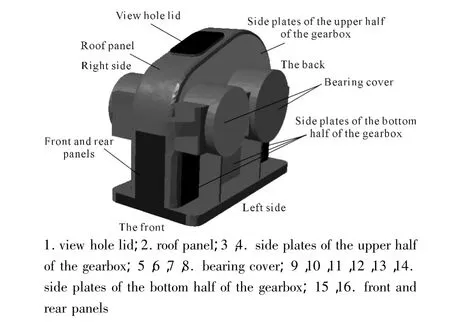
Figure 9.The gear box panel definition
The panel acoustic contribution coefficient is shown in Figure 10,noted that the contributions of the roof panel and the front and rear panels are greater than other panels when the excitation frequency is 1 665 Hz.When the excitation frequency is 667 Hz,the contributions of the roof and side plates of the upper half of the gearbox are bigger.Further analysis indicates that the noise ismainly caused by the panels of the upper half of the gearbox.Reducing of vibration intensity of the panel 2,3,4,15,16 is important to noise control of the gear reducer.

Figure 10.The gear box panel contribution
7.Gearbox im provement
In order to reduce the intensity of vibration of the upper half of the gearbox and make the gearbox natural frequency avoid the 2-times and 5-times the mesh frequency,two low-noise design plans are proposed.The first plan is increase the thickness of the side plates of the bottom half of the gearbox with 4 mm.Another one,the gearbox stiffnesswas strengthened by using ribs on the side plates,as shown in Figure 11.The natural frequency is shown in Table 2.

Table 2.The gear box natural frequencies/Hz
The frequency-noise spectra of the gearbox pre and post improvement is shown in Figure 12,where curve a,b,and c represent the distribution of sound pressure level for the originalmodel and the improved models,respectively.As can be seen,the differences in mesh frequency doubling are considerable.The noise of improved gearbox is reduced obviously when the excitation frequency is below 1 700 Hz.The sound pressure level is reduced about 12 dB at 665 Hz and about9 dB at 1 332 Hz in magnitude.

Figure 11.Improved gearbox
With comparative analysis of the two low -noise design plans,the effect of increasing gearbox thickness and ribs on reducing noise and vibration is almost the same,but the plan 1 will increase more weight and take up more interior room,so it is preferable to provide stiffening ribs on the gearbox.

Figure 12.The frequency spectrum for noise
8.Conclusion
A procedure for predicting the vibration and noise of gear reducer is developed,in which both gear transmission system dynamic characteristics and gearbox dynamic characteristics are considered.The dynamic bearing force is taken as the excitation,the gearbox vibrations and noise radiation are calculated by using FEM/BEM.The resonant frequency band of the gearbox is obtained.Then the low—noise gearbox was designed base on the result ofmodal analysis and acoustic panel contribution analysis.It is feasible to reduce the noise radiation of the gearbox through increasing the structural stiffness of the gearbox and reducing the vibration of the panelswhose acoustic contribution coefficients are positive and values are large.
[1] Mohamed SA,Slim B.An acoustic-structural interaction modeling for the evaluation of a gearbox-radiated noise[J].Mechanical Sciences,2008,50:569-577.
[2] Velex P,Maatar M.Amathematicalmodel for analysing the influence of shape deviations and mounting errors on gear dynamic behaviour[J].Journal of Sound and Vibration 1996,191(5):629-603.
[3] Jean L D,Sylvie LM.Gear impactand idle gear noise:Experimental study and non-linear dynamic model[J].Mechanical System and Signal Processing,2009,23:2608-2628.
[4] Barthod M,Hayne B.Experimental study of dynamic and noise produced by a gearing excited by a multi-harmonic excitation[J].Applied Acoustics,2007,68:982-1002.
[5] Kato M,Inoue K,Shibata K,etal.Evaluation of sound power radiated by a gearbox[C]//Proc.Inter Gearing’94,1994.
[6] Fred BO,Dnnis P,et al.Influence of gear design parameters on gearbox radiated noise[C]//Proc.1994 International gearing conference,1994.
[7] Choy F K,Qian W,et al.Vibration and noise analysis of a gear transmission System[C]//29th Jiont Propulsion Conference and Exhibit,1993.
[8] Yanyan Z,Zhen G.Analysis and Control of Gearbox Noise[J].China Mechanical Engineering,1994,2(5):55-57.
[9] Kahraman A,Blankenship GW.Effect of involute contact ratio on spur gear dynamics[J].Journal of Mechanical Design Des,1999,121:112-118.
[10] Snežana iri Kosti ,Milosav Ognjanovi .The Noise Structure of Gear Transmission Units and the Role of Gearbox Walls[J].FME Transactions,2007,35:105-112.
[11] Tuma J.Gearbox Noise and Vibration Prediction and Control[J].International Journal of Acoustics and Vibration,2009,14(2):1-11.
[12] Lin Tengjiao,Jiang Renke.Numerical Simulation of Dynamic Response and Shock Resistance of Marine Gearbox[J].Journal of Vibration and Shock,2007,26(12):14-17.
[13] SYSNOISE Rev.5.6,Theoretical Manual[Z].Numerical Integration Technologies,Belgium.
工况下齿轮变速箱的低噪声优化方法研究*
陶 庆†1,2,周建星1,孙文磊1,康金胜2
1.新疆大学机械工程学院,乌鲁木齐 830046
2.布鲁内尔大学,英国伦敦 UB8 3PH
提出了一种综合方法能够计算来自变速箱稳定的动态响应和噪声辐射。该方法在考虑时变啮合刚度、齿轮误差和轴承箱体的情况下建立圆柱齿轮传动系统的动力学模型,通过求解数学模型获得动态轴承力的数据。此外,以轴承负载力的数据为激励,数值模拟计算出变速箱的振动和噪声辐射,随着节点动态响应时间的变化,获得了变速箱的噪声频谱和共振频率范围。最后,计算了变速箱面板的共振的频率范围。基于变速箱面板声学贡献分析和振型的结论,对两个齿轮箱的刚度进行了改善。对比分析齿轮箱噪声辐射,确认该方法能有效降低噪声的产生,对变速箱的设计提供了有用的理论指导。
减速器;齿轮箱;振动;噪声;面板声学贡献
TH113.1
10.3969/j.issn.1001-3881.2014.24.005
2014-08-10
猜你喜欢
山东冶金(2022年3期)2022-07-19
家庭影院技术(2020年6期)2020-07-27
家庭影院技术(2019年1期)2019-01-21
家庭影院技术(2018年11期)2019-01-21
家庭影院技术(2018年10期)2018-11-02
车迷(2017年12期)2018-01-18
制造技术与机床(2017年4期)2017-06-22
风能(2016年12期)2016-02-25
人间(2015年8期)2016-01-09
汽车实用技术(2015年8期)2015-12-26

- 机床与液压的其它文章
- Development of remotemonitoring system for hydraulic power station
- Study on the precision ultrasonic densimeter*
- Recognition of license plate based on Fourier Descriptors
- Strong robust control strategy of form ing process in com plex work-pieces with p lastic cement*
- Discussion of conversion detection correlations between gas and hydraulic oil in machine oil pump