
Drag Reducing and Increasing Mechanism on Triangular Riblet Surface*
2014-04-24 10:53FengBeibei封贝贝ChenDarong陈大融WangJiadao汪家道YangXingtuan杨星团
Feng Beibei(封贝贝),Chen Darong(陈大融) Wang Jiadao(汪家道),Yang Xingtuan(杨星团)
1.Key Laboratory of Advanced Reactor Engineering and Safety of Ministry of Education,Institute of Nuclear and New Energy Technology,Tsinghua University,Beijing,100084,P.R.China;2.The State Key Laboratory of Tribology,Tsinghua University,Beijing,100084,P.R.China
1 Introduction
Riblet surface on fluid drag reduction has been a field of intensive research due to its significant impact on energy saving and drag reduction.There are many engineering applications in aeronautics,marine,ground vehicles,and in pipelines as well those can be greatly benefited from any significant amount of drag reduction.Aiming at maximizing the net drag reduction,considerable efforts have been devoted to the theoretical understanding of drag reduction mechanism and the development of an optimum shape of riblets.Suzuki et al[1-2]thought the mean velocity profile in viscous sublayer would be modified,which played a significant role on reducing the drag,and measured the velocity field in triangular riblet region.While Vukoslavcevic et al[3-4]used hot-wires in their measurements.Static pressure distribution in the riblet grooves should generate exclude additional forces in the streamwise direction[5].Vortices induced in the riblet grooves(called the″Second Vortex″theory in some references)are considered the most important factor to analyze the mechanism of the turbulent drag reduction over riblet surfaces[6].Thanks to the experiments and simulations carried out by many laboratories,the development of optimum shape of riblets is available,including different cross-section shapes,i.e.,triangular,rectangular,trapezoidal,sawtooth,and scalloped ones[7-11].Luchini et al[12]suggested that riblet surface can hamper the lateral component of the near-wall flow,and wall shear stress.Choi et al[13]supported this view by experimental investigations.Wang[14]studied experimentally the flow velocity and turbulent characteristics on riblet surface to explore the drag reduction mechanism in water tunnel.Yu et al[15]developed a numerical method to study drag reduction mechanism on a symmetric V-groove spaced triangular and valley curvature riblet surface.But,most of the researches merely focused on the reduction of surface friction drag[15].For the riblet surface,the pressure drag resulting from the deviation of static pressure has an important effect on the drag of friction in high-speed air flow.However,numerical techniques have still lagged experimental studies due to the lack of computational resources,especially for the numerical simulation of drag reduction on riblet surface in high-speed air flow.
The objective of the present study is to propose a simple and accurate numerical treatment for the flow characteristics inside the riblet grooves through computational simulation which was often adopted to study the flow characteristics for high-speed air flow[16],and to analyze drag reducing and increasing mechanism on triangular riblet surface.The proposed method in this paper is to avoid the heavy computational effort needed in mapping techniques and the excessive grid clustering near the riblet surface as well.In addition,the method is intended to be used for perpetual computations for different geometrical parameters while the Mach number ranging from Ma=0.05to Ma=0.95.For this purpose,a finite volume code is modified to reconstruct the cells near the riblet and a second-order upwind discretization is used in calculation at the newly constructed surfaces.The reliability of the method is judged by comparing the results with those of experiments[17].The underlying changes along with mach number inside riblet grooves are presented to explain the mechanism of drag reduction and increase.
2 Numerical Approach
Numerical simulations based on k-εturbulence model are conducted to study the flow characteristics in thin triangular riblet grooves.The k-εturbulence model is proved to be a useful tool for the understanding of mass transfer and Reynolds stress in momentum equation in turbulence boundary layer of high-speed air flow[18]compared with the k-ωturbulence model which is based easily on the method of the near wall function[19].The flow characteristic is described by the distributions of velocity field,mass transfer,static pressure and Reynolds shear stress.
2.1 Treatment of cut cell
The challenge in the present study is to treat an infinitesimal body whose thickness is less than the nominal grid sizes.Schematic description of the problem is shown in Fig.1.Such tiny riblets can be represented in rectangular coordinate system.To avoid the heavy computational effort followed by mapping techniques and the excessive grid clustering near the riblets surfaces as well,a modified calculation unit is adopted to simulate the flow characteristics inside riblet grooves,as shown in Fig.1.
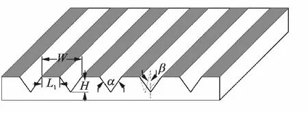
Fig.1 Riblet configuration described by five variable parametres
With the inclusion of the riblet surface and smooth surface inside the domain,the calculation unit is shown in Fig.2.Force analysis focuses on four different parts of the riblet surface compared with a smooth surface.Furthermore,the flow characteristic parameters on every part of the riblet surface can also be obtained.

Fig.2 Transverse view of numerical grids
A transverse view of the numerical grid in the vicinity of riblets is shown in Fig.2for the thin triangular riblet surface.
2.2 Computational details
The computational domain has a dimension of 120μm×100μm,which is relatively larger than the minimal riblet groove unit.The riblets are described with four geometrical parameters despite of their various geometry.In this paper,nineteen cases with certain geometry have been studied while Mach number ranging from Ma=0.05to Ma=0.95with interval of 0.05.Renormalisation group(RNG)k-εturbulent model is used with consideration of pressure gradient.To avoid the false diffusion effect,quadratic upstream interpolation for convective kinetics(QUICK)format is used in the numerical method.No-slip boundary conditions on the channel wall are adopted.Calculation range of geometric parameterαis set from 60°to 120°,and riblet depth dfrom 10μm to 100μm,respectively.Moreover,computational domain field covers

Equation solver adopts Fluent 6.3.26,pressure based and Green-Gauss node based cases.The fluid medium is air,with standard initial conditions(101 325Pa,25°C).Convergence standard is 10-6for continuity equation,others 10-5.
The calculating object has 16 875cells,34 025faces,and 17 151nodes in the directions.Uniform meshes are used in every calculation cases.To obtain credible results,grid-independent verification is conducted to study the effect of grid size on distribution of wall static pressure and shear stress through comparision of four groups of meshes with densities of 50 625,60 241,68 527and 76 257,respectively.Results indicate that the distribution of wall static pressure and shear stress almost remains the same when computational grid is encrypted from 68 572 to 76 257,with deviation of 0.8%wall static pressure and 1.5%wall shear stress.Thus,the computational grid with density of 68 572is adopted in this paper.
The number of grid points near the wall and inside the grooves is much larger than that of the slowly-changed flow region.The no-slip boundary condition is adopted in simulation cases.The turbulent flow is assumed fully developed over the riblets so that the inlet/outlet boundary conditions are simply assigned in the directions.The fluid material is defined as compressible gas.The Courant number is 1 000,which is already fully convergent with high efficiency after 100iterations.
In the case with Ma=0.2,the residual value for each variable degrades below 10-3,judging that the calculation is fully convergent.The residual value curves of monitored parameters are presented in Fig.3.
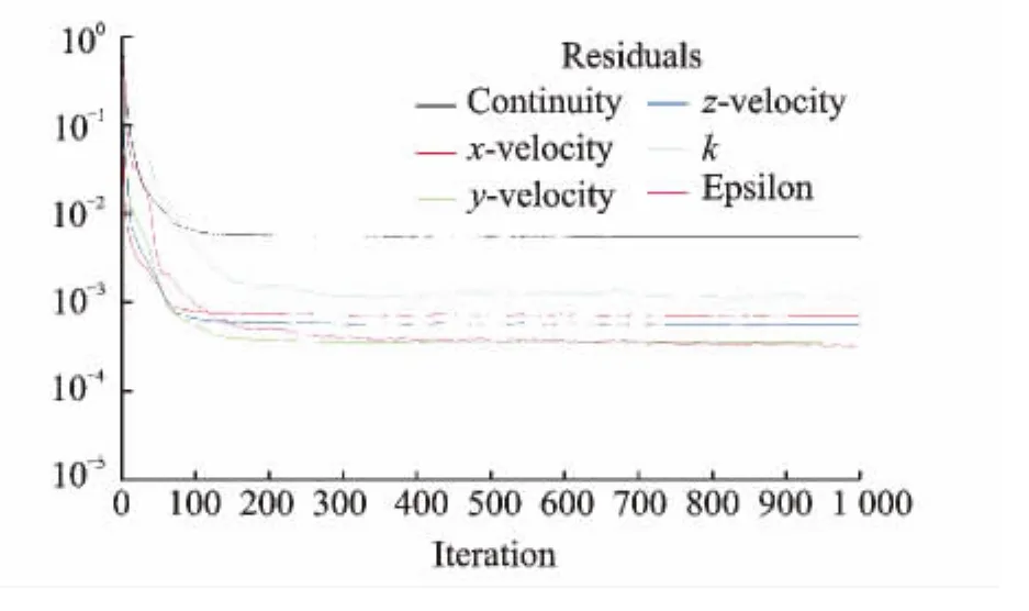
Fig.3 Residual monitors of continuity,x-velocity,yvelocity,energy and nut(convergence criterion)
3 Results and Discussion
3.1 Force analysis
Force on riblet surface is analyzed in detail.Viscous force and pressure force are considered as the two main forces applied on the surface.On a smooth surface,pressure drag is zero because no microvortical structure generates on the smooth surface,which will cause deviation of static pres-sure on the front and rear ends of the riblets.Viscous force is now the total force,and due to the strong shear on the smooth surface,skin friction is totally composed of viscous force.On riblet surfaces,an obvious phenomena is that microvortex will be induced in riblet grooves,which greatly degrades the strong wall shear.And,viscous force resulting from the shearing at solid-vapor interface is correspondingly decreasing,which is the main factor of drag-reduced riblet surfaces.Meanwhile,pressure drag is caused by the deviation of static pressure,high pressure at the front end of riblets,and low pressure zone at the rear end of riblets.Besides,it is related to the induced microvortex in riblet grooves.Microvortex affected by the riblet geometry will have an influence on static distribution and pressure drag.Especially,in high-speed air flow the microvortex formed in riblet grooves significantly affects the skin friction,whose characteristics are also closely related to viscous force and pressure force.It is thus necessary to study the microvortex on riblet surfaces.
Taking the flow Mach number Ma=0.8for instance,flow of microvortex is shown in Fig.4.The microvortex center leans to the front end of riblet,resulting in high pressure zone in this area.When Ma=0.8,the average line speed of microvortex is estimated to be 42.8—57.0m/s approximately.High-speed rotation of microvortex is due to energy and momentum transfer at the turbulence boundary layer.And the linear speed and wall shearing are greatly degraded compared with those of a smooth surface,thus causing viscous drag reduction.Table 1shows the force on smooth surface and riblet surface when Ma=0.8.On smooth surface,pressure force is zero when there is no static pressure distribution deviation and viscous force is about 1.6×10⁻²N.So,total force on a smooth surface is equal to viscous force with the value of 1.6×10⁻²N.On the riblet surface,pressure force is about 2.5×10⁻²N due to the static pressure distribution deviation,and viscous force is about 13.1×10⁻²N,which is obviously degraded.It can be found that the total force is less than that of smooth surface.Riblet structure significantly degrades the surface force.
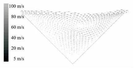
Fig.4 Microvortex induced in riblet grooves

Table 1 Force analysis on riblet surface 10-2 N
3.2 Drag reducing and drag increasing cases
The code is validated by simulation using a certain geometry riblet surface and compared with the smooth surface.Wall friction generates from the intense shear when high-speed air flows over the wall.Joseph and Ke[20-21]emphasized that the fluid speeds in the drag reducing regime were comparable to the speed of shear wave propagation.On riblet surface,the Reynolds shear stress drops owing to the effect of vortices induced inside riblet grooves as shown in Fig.4.The valleys in Fig.5(a)and Fig.6(a)show the degraded zone of Reynolds shear stress to nearly zero which is the dominant factor resulting in drag reduction.Meanwhile,on riblet surface an additional force will generate in the streamwise direction since the dissipation of static pressure exists inside the grooves.Besides,a low pressure zone and a high pressure zone occur on the riblet surface.The pressure differences bring forth additional forces which is significantly related to Mach number as well as the shape and size of riblets.The balance of drag reduction due to degradation of Reynolds shear stress and additional force resulted from zone located at the front end is about 4.9kPa.The additional force relies on the pressure difference which shows significantly inconsistency in both drag reducing and drag increasing cases.
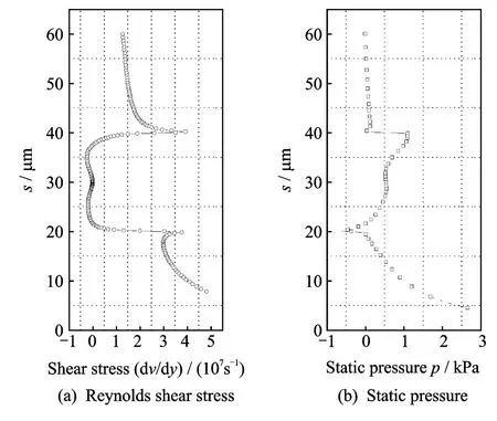
Fig.5 Dissipation of Reynolds shear stress and static pressure on riblet surface when Ma=0.2(Drag reducing case)
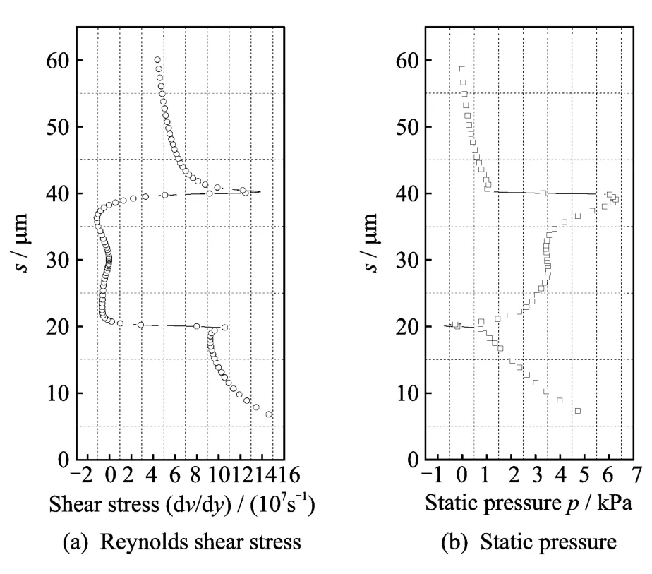
Fig.6 Dissipation of Reynolds shear stress and static pressure on riblet surface when Ma=0.8(Drag increasing case)
3.3 Reynolds shear stress
Reynolds shear stress is plotted in Fig.5(a)for the drag reducing case where the stress is suppressed due to vortices induced in riblet grooves as shown in Fig.4.Reynolds shear stress is greatly weakened compared with that on the smooth surface both in drag reducing and drag increasing cases.The curve valley of Reynolds shear stress is identical and the curve shifts up when close to the end of grooves.Accordingly,wall friction will decrease resulting in drag reduction in the case of optimized riblet surface.
3.4 Static pressure and pressure drag
Distribution of static pressure is modified over thin triangular riblet surface.High pressure zone and low pressure zone at several locations of riblet grooves are verified,which results in the exclude additional forces on riblet surface.The force generates from the deviation of static pressures on the front and rear ends of a riblet groove.
Fig.7illustrates the distribution of wall static pressure on smooth surface and riblet surface when Ma=0.8.Regardless of Mach number,it would be almost the same distribution as that of static pressure.In the simulation,the value of center pressure of high pressure zone located at the rear end of groove is 19.0kPa,while the value of low pressure on triangular riblet surface is 4 943Pa.Consequently,pressure differences would lead to the wall friction up and down.

Fig.7 Dissipation of wall static pressure on smooth surface and riblet surface when Ma=0.8
Moreover,dissipation of Reynolds shear stress and static pressure in drag reducing and increasing cases are shown in Figs.5,6.In spite of Ma,Reynolds shear stress is obviously degraded.But pressure difference shows exponential growth along with Ma.The gap between peak and valley of static pressure on riblet surface is increased and the additional pressure drag is bigger than the decreased wall friction due to the degradation of shear stress.
The pressure values on riblet surface increase significantly with the growth of Ma,as shown in Fig.8.

Fig.8 Growth of maximum static pressure in the center of high-pressure zone when Ma=0—0.95
The increase of static pressure with Mafits an exponential function,which can be described as follows

where yis the maximum static pressure and xthe Mach number.A drag increasing trend,especially of the pressure drag,exists due to the significant growth of static pressure along with Ma.In different simulation cases,the distribution of static pressure remains the same,especially the exponential growth of center static pressure.It is independent of riblet geometry.The coefficients A1,t1,y0however are closely related to the riblet geometry.Different riblets affect the distribution of static pressure,which is the main reason to optimize the configuration parameters of riblets.Distribution of static pressure and pressure drag will change when the shape and size of riblets vary.
4 Conclusions
Research on viscous drag reduction becomes more and more important nowadays due to the shortage of fossil fuel and its high prices.Riblet surface,as one of successful and reliable passive techniques on drag reduction and increase,is investigated numerically in this paper.The accurate numerical treatment based on k-εturbulence model for thin triangular riblet surface at high-speed air flow is proved to be an efficient method to study the characteristics of flow and drag reducing and increasing mechanism.Several typical simulation cases are adopted to explore drag reducing and increasing mechanism through flow alteration analysis.Microvortex induced in riblet grooves will greatly reduce the viscous force and correspondingly pressure force resulting from the deviation of static pressure occurs,which leads to drag increase.In this paper,force analysis on riblet surface is performed and compared with smooth surface.With the triangular riblets aligned on the surface,the shear stress will be significantly decreased and leads to an obvious valley on the curve of distribution of wall shear stress.Accordingly,drag reduction would result from the decreased shear stress.The additional force generating from deviation of static pressure on the front and rear ends of the riblet groove will lead to pressure drag increase,showing exponential growth with Mach number.
The proposed numerical method in this paper is useful and efficient for triangular riblet surface on drag reducing and increasing mechanism and flow structure analysis.
[1] Suzuki Y,Kasagi N.Turbulent drag reduction mechanism above a riblet surface[J].AIAA Journal,1994,32(9):1781-1790.
[2] Garcia-Mayoral R,Jimenez J.Drag reduction by riblets[J].Philosophical Transactions of the Royal Society A:Mathematical,Physical and Engineering Sciences,2011,369(1940):1412-1427.
[3] Vukoslavcevic P,Wallace J M,Balint J L.Viscous drag reduction using streamwise-aligned riblets[J].AIAA Journal,1992,30(4):1119-1122.
[4] Park S R,Wallace J M.Flow alteration and drag reduction by riblets in a turbulent boundary layer[J].AIAA Journal,1994,32(1):31-38.
[5] Okamo Toshiki,Yoshisaki Takashi,Kobayashi Masato.Drag reduction in pipe flow with riblet[J].Nippon Kikai Gakkai Ronbunshu,B Hen/Transactions of the Japan Society of Mechanical Engineers Part B,2002,68(668):1058-1064.
[6] Zhang H Y,Yang H X,Li G.Numerical study of turbulent drag reduction over riblet surface[C]∥Pro-ceedings of the International Offshore and Polar Engineering Conference.Vancouver,Canada:[s.n.],2008:441-445.
[7] EL-Samni O A,Chun H H,Yoon H S.Drag reduction of turbulent flow over thin rectangular riblets[J].International Journal of Engineering Science,2007,45(2/8):436-454.
[8] Jimenez Javier.Turbulent flows over rough walls[J].Annual Review of Fluid Mechanics,2004,36:173-196.
[9] Peet Yulia,Sagaut Pierre.Theoretical prediction of turbulent skin friction on geometrically complex surfaces[J].Physics of Fluids,2009,21(10):105105.
[10]Bechert D W,Bruse M,Hage W,et al.Experiments on drag-reducing surfaces and their optimization with an adjustable geometry[J].Journal of Fluid Mechanics,1997,338:59-87.
[11]Gruneberger Rene,Hage Wolfram.Drag characteristics of longitudinal and transverse riblets at low dimensionless spacings[J].Experiments in Fluids,2011,50(2):363-373.
[12]Luchini P,Manzo F,Pozzi A.Resistance of a grooved surface to parallel flow and cross flow[J].J Fluid Mech,1991,228:87-109.
[13]Choi K S.Breakdown of the Reynolds analogy over drag-reducing riblets surface[J].Applied Scientific Research(The Hague),1993,51(1/2):149-154.
[14]Wang Jinjun,Lan Shilong,Miao Fuyou.Drag reduction characteristics of turbulent boundary layer flow over riblets surfaces[J].Shipbuliding of China,2001,4:1-5.(in Chinese)
[15]Yu Lei,Yang Xudong.Numerical analysis of turbulent drag reduction using riblets[J].Aeronautical Computing Technique,2009,39(1):56-59.(in Chinese)
[16]Fang Yihong,Liu Yifang,Ye Xinfu.Existence of shocklets in supersonic boundary layer and its relation with 3-D disturbance[C]∥2nd WSEAS International Conference on Fluid Mechanics and Heat and Mass Transfer.Corfu Island,Greece:[s.n.],2011:152-157.
[17]Joseph D D,Renardy Y.Fundamentals of two-fluid dynamics:Mathematical theory and applications[M].New York:Springer-Verlag,1993.
[18]Sheikhy Nasrin,Bahrami Milad,Rahimi Asghar B.Analyzing the cross section effect of hypersonic flow past a conical body via perturbation method[C]∥Proc IASME/WSEAS Int Conf Fluid Mech Aerodyn.Moscow,Russia:[s.n.],2009:182-187.
[19]Beghidja A,Gouidmi H,Benderradd R.Study of the interaction shock wave boundary layer with the K-ω turbulence model[J].WSEAS Trans Inf Sc Appl,2006,3(5):921-926.
[20]Joseph D D,Christodoulou C.Independent confirmation that delayed die swell is a hyperbolic transition[J].J Non-Newtonian Fluid Mech,1995,48(3):225-235.
[21]Ke Feng,Liu Yingzheng,Jin Chunyu,et al.Experimental measurements of turbulent boundary layer flow over a square-edged rib[J].Journal of Hydrodynamics,2006,18(Suppl 3):461-464.(in Chinese)
猜你喜欢
金山(2022年4期)2022-04-09
阅读(书香天地)(2021年11期)2021-03-08
意林·全彩Color(2019年9期)2019-10-17
知识就是力量(2019年4期)2019-04-20
百科探秘·航空航天(2017年3期)2017-07-12
百科探秘·航空航天(2017年5期)2017-07-10
中国建筑装饰装修(2017年2期)2017-06-05
晚报文萃(2015年11期)2016-01-11
恋爱婚姻家庭(2015年8期)2015-07-21
飞碟探索(2012年5期)2012-09-22
 Transactions of Nanjing University of Aeronautics and Astronautics2014年1期
- Transactions of Nanjing University of Aeronautics and Astronautics的其它文章
- Lattice Boltzmann Flux Solver:An Efficient Approach for Numerical Simulation of Fluid Flows*
- Experimental Investigation on Flow and Heat Transfer of Jet Impingement inside a Semi-Confined Smooth Channel*
- Flapping Characteristics of 2DSubmerged Turbulent Jets in Narrow Channels*
- Critical Length of Double-Walled Carbon Nanotubes Based Oscillators*
- Identification of Time-Varying Modal Parameters for Thermo-Elastic Structure Subject to Unsteady Heating*
- Optimal Delayed Control of Nonlinear Vibration Resonances of Single Degree of Freedom System*