
Performance of Dual-throat Supersonic Separation Device with Porous Wall Structure
2014-07-18 11:56额日其太,韩景,段然等
Performance of Dual-throat Supersonic Separation Device with Porous Wall Structure
Eriqitai (额日其太)1,*, HAN Jing (韩景)2, DUAN Ran (段然)1and WU Meng (吴盟)1
1School of Energy and Power Engineering, Beihang University, Beijing 100191, China2China Huanqiu Contracting & Engineering Corporation, Beijing 100029, China
In this paper, a dual-throat supersonic separation device with porous wall has been proposed to solve the starting problem of supersonic separator, and the feasibility of the proposed device has been tested numerically and experimentally. Its flow characteristics have been investigated and the effect of some important parameters including nozzle pressure ratio (RNP), inlet temperature and swirl intensity were examined. In the device, the supersonic flow state and strong centrifugal acceleration of 240000g can be obtained, which are necessary for the condensation and separation of water vapor. The supersonic region in the device enlarged and the shock wave shifted downstream along with the increasing RNP. The separation performance was improved with the increasing RNPand the inlet temperature. The best separation performance in this study was obtained with ΔTd=28 K.
supersonic separation, cyclone gas/liquid separation, porous wall, dual-throat
1 INTRODUCTION
Supersonic separator is a unique combination of known physical processes, aerodynamics, thermodynamics and fluid-dynamics, to make a revolutionary gas conditioning process to separate heavy hydrocarbon and water vapor from natural gas after glycol and turbo-expander [1-4]. It combines expansion, cyclone gas/liquid separation and re-compression in a compact static device with similar thermodynamics to a turboexpander. The device, operated without rotating parts and chemicals, ensures a simple and environmentally friendly separation, with a high reliability and availability, suitable for de-manned operation [5, 6].
To date, the reports on the supersonic separation technology are very limited and mainly focus on gas separation process of high-pressure natural gas flow (with inlet pressure more than 3.5 MPa) from gas fields. Two generations of TwisterTMSupersonic Separator [7-11] have been developed which include adiabatic cooling of gas mixture in a supersonic nozzle and separation of liquid phase. The first generation of TwisterTMdevice is shown in Fig. 1, in which the separation of liquid phase is performed by passing the gas-liquid mixture around a wing section by a deflection of the flow from a simple linear flow. As a result, centrifugal forces arise due to the deflection, leading to the separation of liquid drops. A disadvantage of this known method is its low efficiency, because under the deflection of the supersonic gas flow, shock waves occur, which raise the temperature of the gas, and lead to the unwanted vaporization of part of condensed drops back into the gaseous phase. To overcome this disadvantage, the second generation of TwisterTMsupersonic separator was designed. As shown in Fig. 2, there is a swirling device with guide vanes upstream the nozzle to create swirling velocity component, and no shock waves occur. Another improvement of the second generation separator is that the Laval nozzle cross-section is changed from circular shape to annular shape, so the maximum settlement distance becomessmaller with the same cross-sectional area of throat. A disadvantage of this separator is its large viscous loss especially when it is applied to low flow rate of gas well [12], because the radius difference of the two circles becomes smaller when the flow rate is decreased.

Figure 1 Artist impression of the first generation of TwisterTMdevice

Figure 2 Artist impression of the second generation of TwisterTMdevice

Figure 3 Schematic diagram of dual-throat supersonic separation1—inlet; 2—swirling generator; 2-1—vanes for swirl generator; 3—Laval nozzle; 3-1—converging section of Laval nozzle; 3-2—first throat; 3-3—diverging section of Laval nozzle; 4—supersonic diffuser; 4-1—converging section of supersonic diffuser; 4-2—second throat; 4-3—diverging section of supersonic diffuser; 5—wet outlet; 6—dry outlet
Alfyorov et al. [13, 14] designed an 3-S separator intended to improve the efficiency. According to his method, the nozzle cross-section is of circular shape, and there is a supersonic diffuser at the end of the working section in order to increase the pressure recovery. This separator had been tested several times. Compared to Joule-Thomson valve and turbo-expander, it could save 10%-20% compressor power for the same extraction level, and extract more C3+from natural gas. Under certain conditions, especially with small concentrations of heavier hydrocarbons, it could separate liquid components that the Joule-Thomson valve could not separate. Although it has been proved to be effective for high-pressure natural gas processing, the separation performance is much worse when it is applied for low pressure gas mixture (inlet-pressure less than 1 MPa) [15]. The reason is the starting problem caused by the Dual-throat in the 3-S separator, throat of the nozzle and throat of the supersonic diffuser, when inlet pressure is low.
In this paper, the use of porous wall to solve the starting problem is proposed. The dual-throat supersonic separation device with porous wall structure has been designed, its flow characteristics are investigated numerically and experimentally, and some important parameters including the inlet pressure, temperature and swirling intensity are investigated.
2 SOLUTION TO THE STARTING PROBLEM WITH POROUS WALL STRUCTURE
2.1 The starting problem
As mentioned, there is a supersonic diffuser in 3-S separator to make air decelerate from supersonic to subsonic velocities. The efficiency of the supersonic diffusers used to accomplish this deceleration has an important impact on the performance of the separator. The loss occurring in the shock associated with the transition from supersonic to subsonic flow is of the most interest in the supersonic diffuser designing. As shown in Fig. 3, an isentropic deceleration from supersonic velocity to subsonic may be visualized as follows: The converging section of supersonic diffuser in which supersonic flow exists gradually contracts, reducing the Mach number (Ma) to unity at a point known as the second throat. If a normal shock occurs exactly at this minimum area point and the flow then becomes subsonic, the diverging section of supersonic diffuser would permit subsonic diffusion to decelerate. In practice, completely isentropic deceleration involving a normal shock at the second throat cannot be realized. This is because after Laval nozzle connected with the high pressure source, the establishment of supersonic flow in the Laval nozzle is preceded by a shock travelling downstream from the first throat. Due to the emergence of the shock, the airflow total pressure dropped, so that the flow capacity of the supersonic diffuser decreases. The second throat area according to the isentropic flow designed will not be able tomake the shock pass through the divergent section of the Laval nozzle into the supersonic diffuser. The shock is located in the divergent section of Laval nozzle where the Mach number is high, so the loss of total pressure caused by shock is large. This flow state is called unstarting. If the shock travels downstream from the Laval nozzle into supersonic diffuser and stops at a position of divergent section of supersonic diffuser, the state is called unstarting.
2.2 Solution to the starting problem
For efficient operation, supersonic diffuser should operate in a started mode. In recent years, supersonic inlet/diffuser research been carried out both experimentally and computationally. The traditional solution is enlarging the area of the second throat, so that the flow capacity of the supersonic diffuser increased, and the normal shock travelled downstream from the diverging section of the Laval nozzle into supersonic diffuser. It has been found, however, that a position of the normal shock upstream or at the second throat is unstable and unattainable in practice [16]; and it is observed that the flow beyond the second throat then remains supersonic, and Mach number increasing because of the increasing area; hence, the farther the shock occurs downstream, the higher will be its Mach number. As previously noted, this is to be associated with increased loss. So this solution is not suitable.
Another common solution is a variable-geometry second throat. One-dimensional flow in theory and flows observed in practice all indicated that a diffuser employing a variable-geometry second throat might allow the establishment of flow patterns giving higher energy recoveries than the fixed throat. After the initial shock formed on starting the diffuser had passed through, a flexible wall would allow the second throat to be reduced to such an area that the local Mach number was unity. If the transition to subsonic flow occurred closely downstream of this reduced second throat, it would occur where the channel had considerably smaller area than in the area of a fixed wall. Hence if a position of the transition just downstream of the second throat is stable, loss should be smaller in accordance with the reduction of Mach number. But there is no space for mechanical equipments in supersonic separator to adjust the geometry of the second throat.
In this paper, porous wall structure was proposed to solve the starting problem. Fig. 4 is the pressure contour of numerical simulation while it is unstarting, and the view of pressure field at the 2nd throat is enlarged. As is shown, when it is unstarting, the pressure of converging section of the supersonic diffuser is higher than it of diverging section, so using the porous wall to connect the two areas to increase the flow capacity of the supersonic diffuser is proposed.
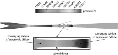
Figure 4 Pressure field while unstarting (RNP=2.25, pin=0.7 MPa, Tin=300 K, γ=70%)
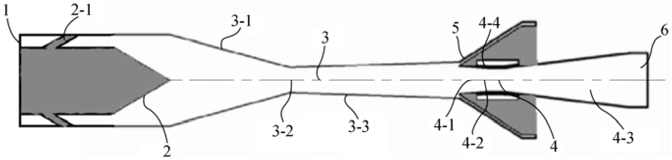
Figure 5 Schematic diagram of Dual-throat supersonic separation with porous wall1—inlet; 2—swirling generator; 2-1—vanes for swirl generator; 3—Laval nozzle; 3-1—converging section of Laval nozzle; 3-2—first throat; 3-3—diverging section of Laval nozzle; 4—supersonic diffuser; 4-1—converging section of supersonic diffuser; 4-2—second throat; 4-3—diverging section of supersonic diffuser; 4-4—porous wall; 5—wet outlet; 6—dry outlet
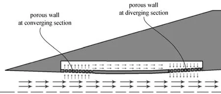
Figure 6 Flow schematic diagram of porous wall structure

Figure 7 Schematic graph of constructed dual-throat supersonic separation with porous wall
Figure 5 shows the schematic diagram of the porous wall proposed for this study. There are two pieces of porous wall in supersonic diffuser, one is located in converging section of the supersonic diffuser, and another one is located in diverging section of the supersonic diffuser. Fig. 6 is the partial enlargement sketch of gas flow condition in the porous wall. As is shown, when it is unstarting, fluid will flow through the porous wall, so that the flow capacity of the supersonic diffuser increased, and the normal shock travelled downstream from the diverging section of the Laval nozzle into supersonic diffuser, so as to achieve starting. After it is started, the difference of the pressure of converging section of the supersonic diffuser and diverging section is smaller, so the flow capacity of the supersonic diffuser decreased. This ingenious structure allows a small size second throat to complete the starting, so the Mach number of the second throat is reduced, which is to be associated with decreased loss.
3 EXPERIMENTAL APPARATUS AND PROCEDURE
3.1 Device
Figure 7 shows the structure of the dual-throat supersonic separation device with porous wall proposed in this study. The device is composed of four key parts including swirling generator, Laval nozzle, supersonic diffuser and porous wall. Comparing with the traditional structure, the swirling generator and diffuser are improved to reduce the energy loss and improve the separation performance. Origin of coordinates is located in Laval nozzle inlet, and the χ-axis is along the flow direction.
3.1.1 Structure of swirling generator
In the traditional structure, the rotation of the two phase flow is generated by a swirling ring setup in the downstream of the diverging nozzle. However, shock waves due to the collision of the swirling ring and high speed flow might increase the energy loss and even destroy the low-pressure and low-temperature environment which is necessary for the condensation of heavy components. To overcome this disadvantage, a novel structure of swirling generator is designed. As shown in Fig. 8, the swirling generator is upstream of the Laval nozzle. It is composed of 12 arced vanes and the height of the swirling generator H=90 mm, the minimum distance between two vanes b=9.5 mm. When the gas flow passes through these channels, it is accelerated and finally enters the nozzle with the tangential velocity component. Its axial velocity is much less than the sound velocity. Thus, shock wavescaused by the swirling generator are completely eliminated [17].

Figure 8 Structure diagram of swirling generator
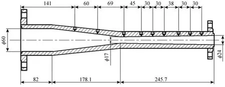
Figure 9 Geometric graph of Laval nozzle (mm)
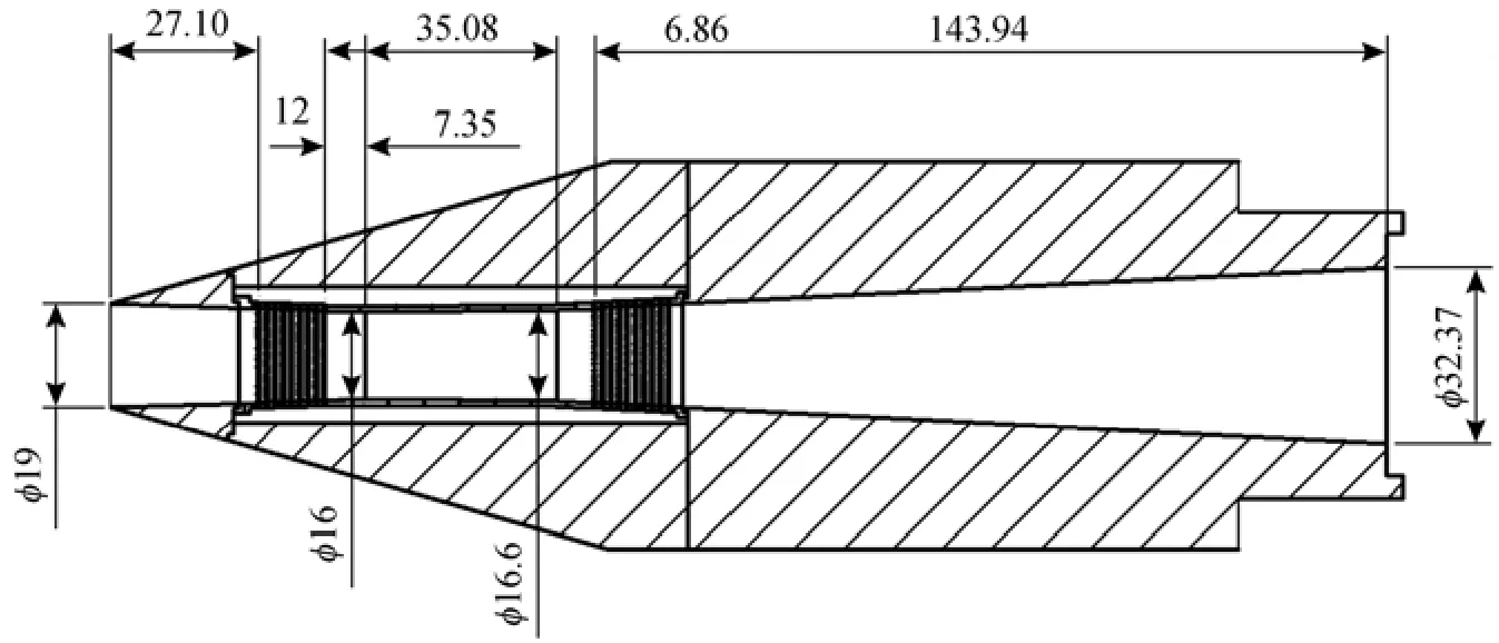
Figure 10 Geometric graph of porous wall (mm)
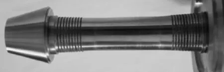
Figure 11 Picture of porous wall
3.1.2 Laval nozzle
The Laval nozzle is a main component of the supersonic swirling separator as heavy components condense and mixture of gas and droplets are separated in this part. The structure parameters of Laval nozzle are determined according to the gas supply ability of gas supply system in the lab, and annotated in Fig. 9.
3.1.3 Porous wall

Figure 12 Schematic diagram of experimental process and apparatus
In this work, porous wall structure was proposed to solve the starting problem as shown in Figs. 10 and 11. There are two pieces of porous wall in supersonic diffuser, one located in convergent section of the supersonic diffuser with 720 holes equally divided into 9 rows, and another one located in divergent section of the supersonic diffuser with 800 holes equally divided into 10 rows. The hole diameter is 1 mm. The width of the connecting channel is 3.8 mm.
3.2 Experimental procedure
To investigate the separation performance of the dual-throat supersonic separation device, an experimental process and a measurement system were set up as shown in Fig. 12. The high pressure air is supplied by a gas compressor with the maximum pressure of 0.7 MPa. The temperature of the high pressure air is adjusted by the electric heater. The micro water droplets generated by an atomizer mixed with the air flow in the mixer. The role of the filter is to remove the big liquid water drops, so that the measurement is not affected. The gas mixture with certain temperature enters the dual-throat supersonic separator, and the water vapor of the wet air condenses in the Laval nozzle. The liquid film on the nozzle wall is discharged together with a small portion of gas from the wet outlet. The dry gas goes out of the device after it passes through supersonic diffuser with porous wall, which is used for the pressure recovery, and then vents into the atmosphere.
3.3 Measurement system
The measurement system consists of instruments measuring the temperature, pressure, and dewpoint temperature.
3.3.1 Measurement of dewpoint temperature
Dew point temperature is representative for the moisture content. At the same temperature, the lower dewpoint temperature indicates that the moisture content is less. The dewpoint temperature is obtained by HMT3307 Humidity and temperature transmitter (Vaisala, Holland) with the measuring range of −60 °C to 60 °C (accuracy ±0.7 °C).
3.3.2 Measurement of static pressure and temperature Except for the inlet and dry outlet, eight pressure measurement points are set on the wall of Laval nozzle along the flow direction shown in Fig. 9. The gauge pressure is obtained by the pressure probes (JYB-KOHAA1, 0.5% FS, ColliHigh, China) with the measuring range of 0-1.0 MPa and a multifunction data acquisition card (PXI-6259, NI, USA). The temperature is obtained by platinum resistor Pt100 with the measuring range of −50 °C to100 °C (accuracy ±1.5 °C).
3.4 Indexes of performance
In order to investigate the separation performance of the designed device and proposed solution, experiments are carried out under various conditions. The removal efficiency of water vapor is the most important index for the evaluation, which is described by the dewpoint depression, ΔTd, between the inlet and dry outlet as defined as follows:

where superscript in and dry represent the inlet and dry outlet respectively. The better performance corresponds to higher ΔTd, and smallerdrydT.
Another important index may be used to evaluate the energy recovery ability which is described by RNPand pressure loss factor σ. They are defined as
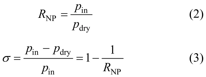
where pinand pdryrepresent the pressure at inlet, dry outlet of the supersonic separator.
3.5 Experimental results
3.5.1 Feasibility of the proposed solution
In order to test the feasibility of the proposed solution, another dual-throat supersonic separation device without porous wall has been designed. The experiment is carried out with RNP=7, pin=0.7 MPa, Tin= 300 K, γ=70% with the two devices. As is shown in Fig. 13, there is no shock wave in Laval nozzle with porous wall, so the proposed solution is feasible.

Figure 13 Comparison diagram of pressure profile (RNP= 2.25, pin=0.7 MPa, Tin=300 K, γ=70%)
3.5.2 Effects of RNP
In order to investigate the effects of RNPto the performance of this device, the static pressure have been measured under twelve different cases of RNP. As seen in Fig. 14, the supersonic region in the device enlarged and the shock wave travelled downstream along with the increasing of the RNP. As seen in Figs. 15 and 16, the dewpoint depression ΔTdincreases along with the increase of RNP, anddrydT decreases along with the increasing of the RNP, so that increasing RNPcan improve the separation performance. The maximum ΔTdand minimumdrydT reach the value of about 25 °C and −11.5 °C, respectively, when RNP= 4.22. This is because that, higher RNPmakes the temperature and static pressure decrease in the supersonic flow. Moreover, higher RNPcauses higher inlet tangential velocity of the gas flow enhancing the centrifugal acceleration, so higher RNPis helpful for separating the droplets. Therefore, increasing RNPimproves the separation performance. But increasing RNPmake the energy loss increase as shown in Eq. (3).
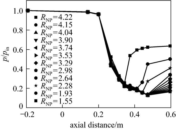
Figure 14 Comparison diagram of pressure profile under different RNP( pin=0.7 MPa, Tin=300 K, γ=70%)
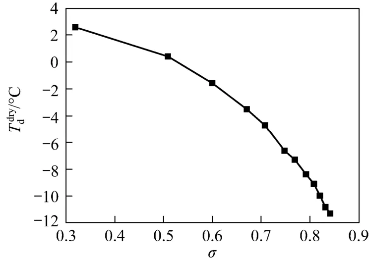
Figure 15 Variation of Tddrywith σ (pin=0.7 MPa, Tin=300 K, γ=70%)
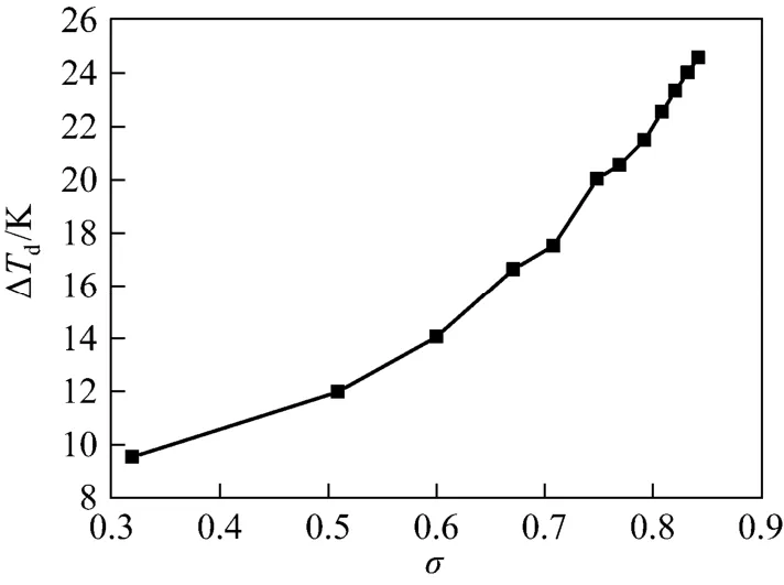
Figure 16 Variation of ΔTdwith σ (pin=0.7 MPa, Tin=300 K, γ=70%)
3.5.3 Effects of Tin
In order to investigate the effects of Tinto the performance of this device, the static pressure and dewpoint temperature have been measured under three different cases of Tin, 283 K (10 °C), 293 K (20 °C) and 303 K (30 °C), respectively.

Figure 17 Comparison diagram of pressure profile under different temperature (RNP=7, pin=0.7 MPa, γ=70%)

Figure 18 Variation of ΔTdwith σ (RNP=7, pin=0.7 MPa, γ=70%)
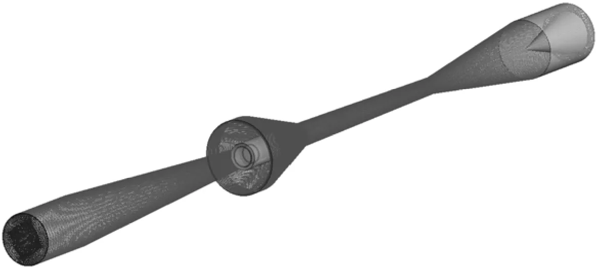
Figure 19 The main grid of the supersonic swirling separator
As seen in Fig. 17, static pressure increases with Tinslightly. In Fig. 18, the dewpoint depression ΔTdincreases along with the increasing Tin. The maximum ΔTdreach the value of about 28 K when Tin=303 K. The influence may be explained by the principle of gas dynamics and gas-liquid equilibrium. The saturated vapor pressure depends on the temperature only. The saturated vapor pressure increases along with the increasing of the Tin, so the moisture content in the mixture at the inlet will increase, thus Tdinwill increase. Because the structures of nozzle and swirling generator are given, the flow field in the nozzle is determined and will not change resulting in a constant pressure and temperature profile in the nozzle. So the saturated content of vapor does not change if the pressure and temperature do not change. Therefore, with the increase of Tin, the inlet content of vapor, the removed content increases, and the separation performances are improved as well.
4 NUMERICAL SIMULATION
Numerical simulation plays an important role in accelerating development cycles and cutting down the cost of experiment. In this paper, the flow characteristics of the dual-throat supersonic separator with porous wall and some important parameters including RNPand swirling intensity are investigated numerically.
4.1 Numerical calculation method
The numerical calculations were carried out with the commercial computational fluid dynamics (CFD) code CFX-5. The shear stress transport (SST) model is chosen as the turbulence model, because the superior performance of this model has been demonstrated in a large number of validation studies [18, 19]. Flow in porous media in ANSYS CFX can be calculated using either a model for momentum loss or a full porous model. The momentum loss model is available in fluid domains, while the full porous loss model is only available in porous domains [20, 21]. In this paper, the momentum loss model is chosen. The porous model is a generalization of the Navier-Stokes equations and of Darcy’s law commonly used for flows in porous regions. So it can be used to model the flows in the porous wall of the supersonic separator where the geometry is too complex to resolve with a grid. The volume porosity γ at a point relates the volume V′available to flow in an infinitesimal control cell around the point, and the physical volume V of the cell:

A grid of the main components including Laval nozzle, supersonic diffuser and porous wall is shown in Fig. 19, and all the nodes are 5.03 million. Pressure inlet with 45° tangential velocity component instead of the subsonic swirler being simulated considering the complexity of the simulation.
Steady-state numerical simulation is specified as the analysis type. Compressible ideal gas is selected as the working medium. Total pressure and total temperature are given as the inlet boundary conditions, and the static atmospheric pressure given for outlet boundary condition. The wall is set to be smooth, no slip, and adiabatic. Criterion of convergence for the calculation is that the normalized residual error is less than 10−5and it does not changes as the iteration goes further.
4.2 Validation of the method
The validity of this method is verified by comparing the wall static pressure ratio of calculation with the experiment result with same conditions (RNP=2.25, pin=0.7 MPa, Tin=300 K, γ=70%). As Fig. 20 shown, the simulation results are largely consistent with the results of experiment, so this method is accurate and feasible.
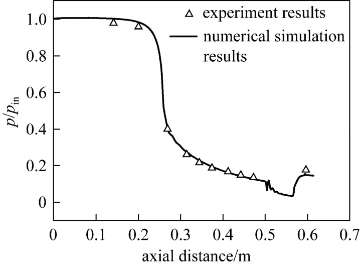
Figure 20 Comparison diagram of pressure profile (RNP= 2.25, pin=0.7 MPa, Tin=300 K, γ=70%)
4.3 The numerical simulation results
4.3.1 The flow state analysis
The simulation is carried out with RNP=2.25, pin=0.7 MPa, Tin=300 K, γ=70%. Fig. 21 is the contour of Mach number without porous wall which shows that there are two normal shocks, one located in Laval nozzle and another located in divergent section of the supersonic diffuser. Fig. 22 is the contour of Mach number with porous wall which shows that the flow speed is reached sonic at the first throat, and then it is accelerated in the diverging part of Laval nozzle, increasing the Mach number to 2.02 in the exit of Laval nozzle, then the supersonic flow contracts gradually in the convergent section of the supersonic diffuser, reducing the Mach number to 1.2 at the second throat, and then accelerates in the divergent section of the supersonic diffuser until an oblique shock make it become subsonic. Compared to without porous wall device shown in Fig. 21, there are no normal shocks but oblique shocks which make total pressure loss small.
Figures 23 and 24 show that the gas flow is maintained in the supersonic state in the diverging part of Laval nozzle, so the low-pressure and low-temperature environment for the condensation has been obtained. There is no shock in Laval nozzle. It is shown that the device accomplishes the start-up, so the porous wall design works effectively. Fig. 24 shows that the lowest temperature is 160 K (−113.5 °C).
Figure 25 is the contour of the centrifugal acceleration distribution, which shows that the biggest centrifugal acceleration is 240000g (approximately 2.35×10⁶m·s−2) which is 24 times that reported in [13]. Fig. 26 is diagram of streamlines, which shows that the flowis highly swirling, providing an advantageous flow field for the drop separation.

Figure 21 Contour of Mach number without porous wall (RNP=2.25, pin=0.7 MPa, Tin=300 K)

Figure 22 Contour of Mach number with porous wall (RNP=2.25, pin=0.7 MPa, Tin=300 K, γ=70%)
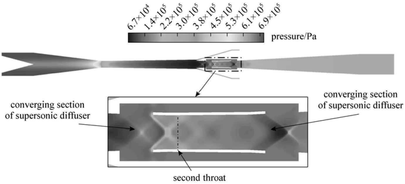
Figure 23 Contour of pressure (RNP=2.25, pin=0.7 MPa, Tin=300 K, γ=70%)
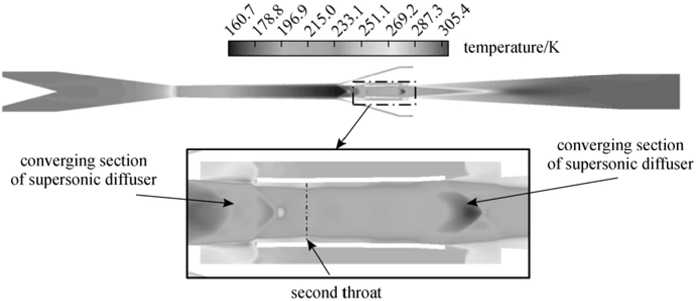
Figure 24 Contour of temperature (RNP=2.25, pin=0.7 MPa, Tin=300 K, γ=70%)

Figure 25 Contour of centrifugal acceleration (RNP=2.25, pin=0.7 MPa, Tin=300 K, γ=70%)
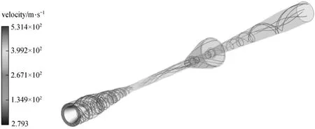
Figure 26 Diagram of streamlines colored with velocity magnitude (RNP=2.25, pin=0.7 MPa, Tin=300 K, γ=70%)
4.3.2 Effects of RNP
Six different cases of RNP, which is defined as the ratio of the total pressure of the inlet to the ambient pressure of the outlet, equal to 7, 4.67, 3.50, 2.37, 2.33 and 1.75 are calculated. The supersonic region in the device enlarged along with the increasing RNP as seen in Table 1, and the maximum Mach number increased as well. This is consistent with the experiment results discussed in Section 3.5.1. As seen in Table 1, when RNP=2.33, the shock position is in the Laval nozzle, so it is unstarting, the mass flow rate of porous wall is 0.041 kg·s−1, while RNP=2.37, the mass flow rate of porous wall reduced to 0.014 kg·s−1, because the shock position is shifted into the divergent section of the supersonic diffuser, the difference of the pressure of converging section of the supersonic diffuser and diverging section became small, so the flow rate decreased and the device achieved the started state. It is consistent with the discussion in Section 2.2. The mass flow rate through the porous wall does not change with the increasing RNPbeyond 2.37, because after it is started, the pressure of converging section and diverging section does not change.
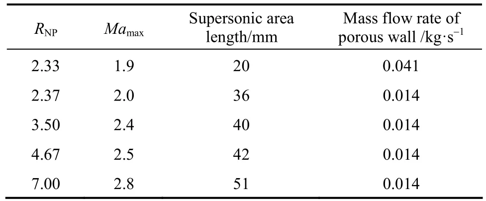
Table 1 Comparison maximum Mach number and supersonic area length of different RNP

Figure 27 Comparison diagram of pressure profile under different RNP(pin=0.7 MPa, Tin=300 K, γ=70%)
Figure 27 shows the variation of wall static pressure with the increase of axial distance under different RNP. The shock was shifted downstream while RNPincreased, and the Mach number upstream the shock increased, so the total pressure loss increased. While RNPless than 2.33, the shock position is in the Laval nozzle, which raise the temperature of the gas, and this leads to the unwanted vaporization of some condensed drops back into the gaseous phase.
5 DISCUSSION ON NATURAL GAS SEPARATION
In order to explore the separation performance of the natural gas, numerical simulations using of natural gas as working fluid are done in this section. The simulation is carried out with RNP=2.25, pin=0.7 MPa, Tin=300 K, γ=70% as the same as it in Section 4.3.1. Figs. 28 and 29 show that, the gas flow is maintained in the supersonic state in the diverging part of Laval nozzle, so the low-pressure and low-temperature environment for the condensation have been obtained. Fig. 30 shows that, the lowest temperature is 189 K (−84.5 °C) which is 20 K higher than it in Section 4.3.1 Fig. 29 is the contour of Mach number which shows that the flow speed reaches sonic at the first throat, and then it is accelerated in the diverging part of Laval nozzle, increasing the Mach number to 1.98in the exit of Laval nozzle. The Mach number is lower than it in Section 4.3.1. The supersonic flow exists gradually contracts in the convergent section of the supersonic diffuser, reducing the Mach number to 1.1 at the second throat, and then decelerates to subsonic after an oblique shock, so the solution of porous wall to the starting problem is also effective while the natural gas is working fluid.
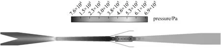
Figure 28 Contour of pressure (RNP=2.25, pin=0.7 MPa, Tin=300 K, γ=70%)
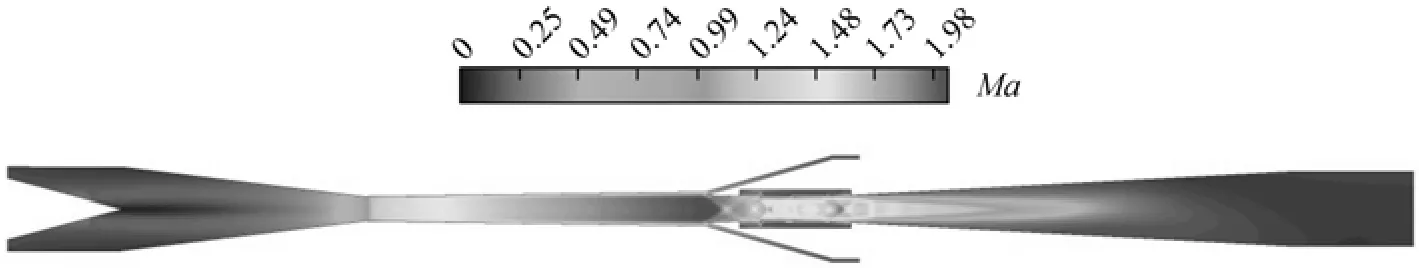
Figure 29 Contour of Mach number (RNP=2.25, pin=0.7 MPa, Tin=300 K, γ=70%)
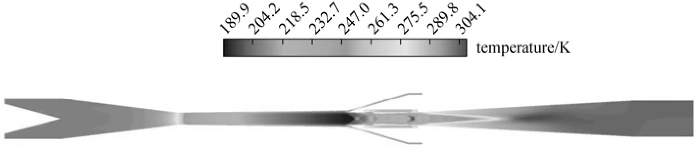
Figure 30 Contour of temperature (RNP=2.25, pin=0.7 MPa, Tin=300 K, γ=70%)
6 CONCLUSIONS
This paper firstly proposes in detail the technique to solve the starting problem of the supersonic separator with two throats by introducing porous wall into the 2nd throat. Numerical simulations and experiments are carried out to test the feasibility of the technique, and results show that because of the porous wall the normal shock wave travelled downstream from the diverging section of the Laval nozzle into supersonic diffuser to achieve the starting.
The numerical calculations were carried out with the CFX-5 using SST model as the turbulence model and momentum loss model as porous model, and the simulation results are largely consistent with the experimental results. Some important parameters including RNP, inlet temperature and swirling intensity are investigated. In the device, the supersonic flow state and strong centrifugal acceleration as 240000g can be obtained, which are necessary for the condensation and separation of water vapor. The supersonic region in the device enlarged and the shock wave travelled downstream along with the increasing RNP. The separation performance is improved with the increase of RNPand inlet temperature. The best separation performance in this study is obtained, with ΔTd=28 K, σ=0.857 when Tin=303 K, pin=0.7 MPa, γ=70%.
In order to investigate the separation performance of the natural gas, numerical simulations using of natural gas as working fluid are done. The solution of porous wall to the starting problem is also effective while the natural gas is working fluid. The experiment is not carried out, but the indoor experiment using with moist air as working medium has a strong reference value.
NOMENCLATURE
A Laval nozzle expanding ratio
Acarea of nozzle throat, mm2
b minimum distance between two blades of swirling generator, mm
g gravity acceleration (=9.81m·s−2)
H height of swirling generator, mm
Ma Mach number (Mach 1=340.29 m·s−1)
nbblade number of swirling generator
pdrydry outlet pressure, MPa
pininlet pressure, MPa
RNPnozzle pressure ratio
T static temperature, K
Tddewpoint, K
Tininlet temperature, K
Tddrydry outlet dewpoint, K
Tdininlet dewpoint, K
ΔTddewpoint depression between inlet and dry outlet, K
V physical volume of the infinitesimal control cell, mm3
V′ volume available to flow in an infinitesimal control cell, mm3
σ pressure loss factor
γ volume porosity of porous wall
REFERENCES
1 Betting, M., “Nozzle for supersonic gas flow and an inertial separator”, US Pat., 6513345 B1 (2003).
2 Brouwer, J.M., Epsom, H.D., Twister, B.V., “Twister supersonic gas conditioning for unmanned platforms and subsea gas processing”, In: Offshore Europe, Society of Petroleum Engineers Inc., United Kingdom (2003).
3 Cao, X.W., Chen, L., Lin, Z.H., Du, Y.J., “Supersonic swirling separators”, Pipeline Technique and Equipment, 27 (7), 1-3 (2008). (in Chinese)
4 Tu, H., Jiang, H., Liu, X.Q., “Application of supersonic separator to natural gas dehydration”, Natur. Gas Ind., (3), 109-111 (2007). (in Chinese)
5 Karimi, A., Abdi, M.A., “Selective removal of water from supercritical natural gas”, In: SPE Gas Technology Symposium, Society of Petroleum Engineers Inc., Calgary, Alberta, Canada, 15 May (2006).
6 Chen, J.X., “Long distance delivery gas hydrate preventive measures and dehydration process”, Ocean Oil, 4 (110), 56-60 (2001). (in Chinese)
7 Okimoto, F., Brouwer, J.M., “Supersonic gas conditioning”, World Oil, 223 (8), 1170-1178 (2002).
8 Okimoto, F., Brouwer, J.M., “Twister supersonic gas condition-studies, applications and results”, In: 82nd Annual GPA Convention, San Antonio (2003).
9 Janssen, J.W.F., Betting, M., “Combined test with improved performance TwisterTMsupersonic separator and the Gasunie cyclone separator”, In: 23rd World Gas Conference, International Gas Union, Amsterdam (2006).
10 Betting, M., Epsom, H., “Supersonic separator gains market accep-tance”, World Oil, 228 (4), 197-200 (2007).
11 Schinkelshoek, P., Epsom, H.D., “Supersonic gas conditioning commercialization of TwisterTMtechnology”, In: 5th GPA Annual Conference, Texas (2008).
12 Han, J., “Research on flow characteristics and separation performance of wet gas in supersonic swirl flow”, MS Thesis, Beihang Univ., China (2012). (in Chinese)
13 Alfyorov, V., Bagirov, L., Feygin, V., Arbatov, A., Dmitriev, L., Rezunenko, V., “Method of and apparatus for the separation of components of gas mixture and liquefaction of a gas”, US Pat., 6372019B1 (2002).
14 Alfyorov,V., Bagirov, L., Dmitriev, L., Feygin, V., Imayev, S., Lacey, J.R., “Supersonic nozzle efficiently separates natural gas components”, Oil Gas J., 103 (20), 53-58 (2005).
15 Liu, H.W., Liu, Z.L., Feng, Y.X., Gu, K.Y., Yan, T.M., “Characteristics of a supersonic swirling dehydration system of natural gas”, Chin. J. Chem. Eng., 13 (1), 9-12 (2005).
16 Matsuo, K., Kim, H.D., “Normal shock wave oscillations in supersonic diffusers”, Shock Waves, 3, 25-33 (1993).
17 Ma, Q.F., Hu, D.P., He, G.P., Hu, S.J., Liu, W.W., Xu, Q.L., Wang, Y.X., “Performance of inner-core supersonic gas separation device with droplet enlargement method”, Chin. J. Chem. Eng., 17 (6), 925-933 (2009).
18 Menter, F.R., “Two-equation eddy-viscosity turbulence models for engineering applications”, AIAA J., 32 (8), 269-289 (1994).
19 Wilcox, D.C., Turbulence Modeling for CFD, DCW Industries, Inc., La Canada, CA, USA (1993).
20 ANSYS Inc., CFX-Slover Modeling Guide, ANSYS Inc. (2009).
21 ANSYS Inc., CFX-Slover Theory Guide, ANSYS Inc. (2009).
2012-09-11, accepted 2012-11-21.
* To whom correspondence should be addressed. E-mail: eriqitai@buaa.edu.cn
 Chinese Journal of Chemical Engineering2014年4期
- Chinese Journal of Chemical Engineering的其它文章
- An Approach to Formulation of FNLP with Complex Piecewise Linear Membership Functions
- Determination and Correlation of Solubility for D-Xylose in Volatile Fatty Acid Solvents*
- Impacts of Power Density on Heavy Metal Release During Ultrasonic Sludge Treatment Process*
- One Step Preparation of Sulfonated Solid Catalyst and Its Effect in Esterification Reaction*
- Effects of Assistant Solvents and Mixing Intensity on the Bromination Process of Butyl Rubber*
- Determination and Correlation of Solubilities of Four Novel Benzothiazolium Ionic Liquids with6PF−in Six Alcohols*