
Industrial-scale Fixed-bed Coal Gasification: Modeling, Simulation and Thermodynamic Analysis*
2014-07-18 12:09HEChang何畅FENGXiao冯霄KhimHoongChuLIAnxue李安学andLIUYongjian刘永健StateKeyLaboratoryofHeavyOilProcessingChinaUniversityofPetroleumBeijing049ChinaHoneychemNanjingChemicalIndustryParkNanjing0047ChinaLiaoningDatangInternational
HE Chang (何畅), FENG Xiao (冯霄),**, Khim Hoong Chu, LI Anxue (李安学)and LIU Yongjian (刘永健),State Key Laboratory of Heavy Oil Processing, China University of Petroleum, Beijing 049, ChinaHoneychem, Nanjing Chemical Industry Park, Nanjing 0047, ChinaLiaoning Datang International Fuxin Coal-To-SNG CO., LTD, Fuxin, China
Industrial-scale Fixed-bed Coal Gasification: Modeling, Simulation and Thermodynamic Analysis*
HE Chang (何畅)1, FENG Xiao (冯霄)1,**, Khim Hoong Chu2, LI Anxue (李安学)3and LIU Yongjian (刘永健)1,31State Key Laboratory of Heavy Oil Processing, China University of Petroleum, Beijing 102249, China2Honeychem, Nanjing Chemical Industry Park, Nanjing 210047, China3Liaoning Datang International Fuxin Coal-To-SNG CO., LTD, Fuxin, China
We have developed a process model to simulate the behavior of an industrial-scale pressurized Lurgi fixed-bed coal gasifier using Aspen Plus and General Algebraic Modeling System (GAMS). Reaction characteristics in the fixed-bed gasifier comprising four sequential reaction zones—drying, pyrolysis, combustion and gasification are respectively modeled. A non-linear programming (NLP) model is developed for the pyrolysis zone to estimate the products composition which includes char, coal gases and distillable liquids. A four-stage model with restricted equilibrium temperature is used to study the thermodynamic equilibrium characteristics and calculate the composition of syngas in the combustion and gasification zones. The thermodynamic analysis shows that the exergetic efficiency of the fixed-bed gasifier is mainly determined by the oxygen/coal ratio. The exergetic efficiency of the process will reach an optimum value of 78.3% when the oxygen/coal and steam/coal mass ratios are 0.14 and 0.80, respectively.
Lurgi gasifier, gasification, syngas, pyrolysis, exergetic efficiency
1 INTRODUCTION
According to the International Energy Outlook 2011 report published by the U.S. Energy Information Administration [1], worldwide total natural gas consumption is expected to expand to 4.78 trillion cubic meters in 2035 from 3.14 trillion cubic meters in 2008. Much of this growth will come from emerging economies like China, where the consumption is forecast to grow at an average rate of 5 percent annually, the highest growth rate worldwide, to a total of 0.30 trillion cubic meters in 2035. Huge market prospects provide exciting opportunities and great challenges for the development of alternative natural gas technology in China, especially the coal to synthetic natural gas (SNG) technology platform [2]. Currently, the typical and recognizable coal gasification technology used in an SNG plant is pressurized gasification of crushed coal in fixed-bed, namely Lurgi gasification, which can handle low-rank coals with high ash, high moisture and stable chemical bonds (e.g. lignite, sub-bituminous and bituminous coals). Since it produces a gaseous fuel with relatively high CH4concentration and a high H2/CO ratio, it is especially suitable for production of SNG as well as other fuels/chemicals (e.g., pipeline gas, methanol, Fischer-Tropsch synoil, dimethyl ether).
Simulation models for fixed-bed gasifiers can provide an effective tool for product composition prediction, thermodynamic analysis and operation optimization. Process modeling software programs, such as Aspen Plus™, are widely used in the simulation of carbonaceous fuel conversion processes. In a number of previous studies, Aspen Plus has been successfully used to simulate an IGCC (integrated gasification combined cycle) plant [3, 4] or a poly-generation system based on Texaco/Shell/Siemens gasification technology [5, 6], coal-to-methanol process, direct coal liquefaction process [7], compartmented fluidized-bed coal gasifier [8], pressurized ash agglomerating fluidized-bed gasifier [9], and coal hydro-gasification process [10]. It is considered to be an excellent process design and simulation tool because of its ability to provide comprehensive property data and simulate a variety of steady-state processes involving many interconnected units.
In a typical fixed-bed gasifier, the relatively low temperature in the upper section of the gasifier, where the coal is dried and pyrolyzed, makes the pyrolysis products, including coal gases and high mass hydrocarbons (tar, phenol, oil, etc.), difficult to decompose or burn. As a result, the pyrolysis products mix with the upflow gases and flow to the other downstream devices where they are recovered as by-products. Therefore, the distribution of the pyrolysis products will affect the composition of syngas. So far, very few studies on this phenomenon have been conducted due to a lack of relevant data [11].
Furthermore, under different gasification conditions (i.e., temperature, pressure, feedstock scale, and coal rank), the coals in fixed-bed gasifiers usually exhibit specific kinetic performance. Because the kinetic/ hydrokinetic data of coal are generally not available in the open literature, most researchers tend to use equilibrium models which are based on a minimization of the Gibbs free energy for process simulation.

Table 1 Proximate and ultimate analysis of raw coal
The equilibrium approach is not ideal because in a fixed-bed gasifier as a countercurrent reactor its axial temperature is not uniform. For example, in the gasification zone of the Lurgi fixed-bed gasifier the axial temperature is in the range of 600-800 °C, while in the combustion zone it can even reach up to 1200 °C in some cases. Li et al. [12, 13] developed an Aspen Plus simulation model of a syngas chemical looping (SCL) gasification process using a multistage equilibrium model. This multistage equilibrium model agreed with the characteristics of chemical reactions and mass transfer in the fixed-bed gasifier. However, it is well known that most gas-solid reactions in practical fixed-bed gasifiers do not approach the ideal chemical equilibrium state. Bhattacharyya et al. [14] proposed a restricted equilibrium gasifier reactor model (RGibbs model in Aspen Plus) to correct the extent of deviation from chemical equilibrium. Restricted equilibrium model is also proposed as a pseudo-equilibrium model [15] or a quasi-equilibrium model [15, 16], which is usually used in simulating fluidized-bed gasifiers and entrained-flow gasifiers.
In this paper, a comprehensive process simulation model using Aspen Plus and General Algebraic Modeling System (GAMS) is developed in order to investigate the steady-state performance of an industrial-scale Lurgi fixed-bed gasifier. The process model is divided into four stages: (1) drying of raw coal in drying zone, (2) coal pyrolysis process, (3) partial oxidation reaction of char in combustion zone, and (4) gas-solid reaction in gasification zone. At each stage, empirical models based on experimental data are used to calculate the gaseous components. Especially, a non-linear programming (NLP) model is formulated for the pyrolysis zone to estimate the product composition including char, coal gases and distillable liquids. A multi-stage model with restricted equilibrium temperature is then developed to study the thermodynamic equilibrium characteristics and calculate the composition of syngas in the combustion and gasification zones. After the model is validated by industrial data, it is used to investigate the thermodynamic performance of the Lurgi fixed-bed gasifier by varying the oxygen/coal ratio and steam/coal ratio.
A number of studies have investigated the thermal efficiency of fixed-bed gasification processes. For example, Juraščík et al. [15], Prins et al. [16, 17], Ptasinski et al. [18] and He et al. [19] evaluated the performance of gasification systems in terms of different thermodynamic efficiency indicators. Their results reveal that the thermal efficiencies of the investigated fixed-bed gasification processes are in a wide range of 55%-90%. Several options ranging from adjusting the gasification design to changing the operating conditions [9, 15, 20, 21] can be used to improve the performance of gasification processes. A major aim of this paper is to estimate the thermal efficiency of the Lurgi fixed-bed gasifier and determine its energy quality and usefulness based on exergy analysis. This thermodynamic analysis is useful for determining the optimum performance of the Lurgi fixed-bed gasifier and the sources of thermodynamic irreversibility. This research therefore offers a detailed framework for the modeling and thermodynamic performance assessment of industrial-scale fixed-bed gasifiers.
2 SIMULATION MODEL
The commercial process simulator Aspen Plus (Version 7.3) is used for simulating the whole gasification process. Additionally, the General Algebraic Modeling System (GAMS) (Version 22.3) is used to model the coal pyrolysis process. Table 1 lists the component attributes of the coal examined in this study. The MIXCINC stream class is chosen as global stream class. Because both coal and ash are treated as non-conventional components in the Aspen Physical Property System, the two built-in models, HCOALGEN and DCOALIGT, are selected to calculate their density and enthalpy, respectively. As for the conventional components, Peng-Robinson equation of state with Boston-Mathias α-function (PR-BM) is used to calculate their physical properties.
Figure 1 depicts the Aspen Plus simulation model. According to the actual gasification process, four Aspen Plus blocks are used to simulate the gasifier: drying zone, pyrolysis zone, combustion zone and gasification zone. The release of moisture bound to the coal into the gas phase of the drying zone is estimated using the built-in FORTRAN calculator of Aspen Plus. The characteristics of the pyrolysis, combustion and gasification zones will be described in Sections 2.1 and 2.2.
The basic assumptions of the model are:
(1) The gasification process is at steady state and the mixing of gas-solid in each reaction zone is perfect.
(2) Ash is inert and does not participate in any chemical reactions.
(3) The char contains only fixed carbon (graphite), and the char conversion rate is set to 98% in the C-ASH unit in Fig. 1.
(4) The pressure loss is not taken into account in the simulation; the heat loss of the whole process is assumed to be 5% of the heat value of coal fed to the gasifier.

Figure 1 Aspen Plus simulation model for the Lurgi fixed-bed gasifier processdrying, pyrolys—yield reactor; SEP-1, SEP-2, C-ASH—separator; M-PRO, MIX-FD—mixer; PAR-OXI—stoichiometric reactor; WGS—equilibrium reactor; COMB—multiple Gibbs reactors/separators; HRSG—heat recovery; PYRGAS—coal gases from pyrolysis reaction; CW—cooling water; LPS—low pressure steam; ST-JAC—jacket steam; STE—steam; OXY—oxygen; UC—unconverted carbon
2.1 Coal pyrolysis process
In the pyrolysis process, three different kinds of products [see Eq. (1)] can be obtained as follows: (1) char is defined as un-distillable material which remains in the form of solid and is assumed to only consist of fixed carbon in this study, (2) coal gases are defined as those components lighter than C6, i.e. CO, CH4, H2, H2O, CO2, etc., and (3) the term ‘liquids’refers to distillable liquids (high-mass hydrocarbons), including tar, phenol, naphtha and oil, whose molar mass is larger than C6. Notice that the liquids components have indefinable compositions and are liquid-like at ambient conditions.

The pyrolysis process is an important step for coal gasification since it strongly influences the distribution of volatile products. Some researchers, in an effort to avoid accounting for the complex chemical-physical reactions, generally use a simple Aspen Plus yield reactor (RYield) with a built-in FORTRAN procedure to model the pyrolysis process, where the total yield of volatiles content is decomposed into simple substances [Cs, Ss, H2, N2, Cl2, and O2] according to the proximate analysis of raw feedstock [8, 22-24]. Nevertheless, the above approach will cause a deviation from practical results that are often observed in the Lurgi gasifier. The gases and solids in the Lurgi gasifier are in countercurrent movement and are at relatively low operational temperature in the pyrolysis zone as well, and so it is not easy to decompose the high-mass hydrocarbons. Yoon et al. [25], Adanez and Labiano [26] and Baliban et al. [27] pointed out that the data obtained from pyrolysis experiments can serve as a guide in predicting the product composition of coal pyrolysis. In this work, the amount of each pyrolysis product is based on typical literature data, as shown in Table 2. The ultimate analysis of distillable liquids is obtained from our laboratory. As listed in Table 3, the tar, phenol, naphtha and oil components are represented by C7H10, C6H6O, C9H10and C8H11, respectively, since these conventional components are available in the Aspen Plus Physical Property Database and their C/H ratios and molar mass are similar to those of the high-mass hydrocarbons.

Table 2 Typical coal pyrolysis data [5, 28]
It should be noted that the quoted data are taken from diverse sources with experimental operatingconditions such as the gasifier pressure, temperature and coal type that are quite different from those of the industrial-scale Lurgi gasifier examined in this study. Accordingly, an approximate mathematical model is used here to gain a more useful insight into the initial composition of high-mass hydrocarbons and to obtain more accurate flow rates for the final vapor products of the pyrolysis process. A description of the mathematical model is given below.
Firstly, the sets of all atomic species Epyr,iand vapor products Cpyr,jare defined as follows:
Sets

Table 3 Ultimate analysis of distillable liquids

where e and c denote each atomic and gaseous species in the pyrolysis reaction, respectively.
Subject to
(1) Atomic C balance:


The terminology is defined in the Nomenclature.
In Eq. (11), two new coefficients, namely R and L, are used to represent the composition ratio constraint relationships between the expected pyrolysis yields and typical experimental pyrolysis yields (listed in Table 2). Using GAMS to solve the above model gives optimumpyr,jCN values and the final overall pyrolysis reaction is shown in Eq. (12).

2.2 Modeling of combustion zone and gasification zone
The gasification process is mainly heterogeneous reactions between carbon and gasifying agents from the viewpoint of chemical reaction. Generally, the rate of a heterogeneous reaction is controlled by not only the chemical reaction kinetics but also the diffusion rates of reactants. For the Lurgi gasifier, both the operational temperature (<1000 °C) and output syngas cooling temperature (<250 °C) are lower than other commercial gasifiers (Texaco, Shell and Siemens,etc.), which make the syngas composition away from equilibrium. On the other hand, for the RGibbs reactor in Aspen Plus, the syngas composition is calculated by minimizing the Gibbs free energy under the assumption of complete chemical equilibrium. A more realistic approach is to use a restricted equilibrium gasifier model which restricts the extent of chemical equilibrium by specifying the certain molar extent or temperature approach for the reactions under study. In this work, the temperature approaches to equilibrium listed in Table 4 are used to specify the number of degrees above the system temperature at which the chemical equilibrium for these reactions are computed. Note that both gasification and combustion zones are modeled as adiabatic reactors (heat duty=0 kJ·s−1), and the temperature approach for the water gas shift reaction (WGS, R4 in Table 4) is assumed for the combustion zone, while a set of linearly independent chemical reactions (R1, R2 and R3 in Table 4) is specified for the gasification zone.

Figure 2 Sequential modular simulation diagram of fixed-bed gasification model

Table 4 Restricted equilibrium reactions in the gasifier [14, 29]
For a fixed-bed gasifier, there are no obvious boundaries between the combustion and gasification reaction zones. In fact, the same reactions can be observed in both zones. However, most researchers still define the boundary between the two zones at the point where oxygen is totally exhausted. Following this convention, the char partial combustion reaction (R5 in Table 4) and water gas shift reaction (R4) are assumed to occur in the combustion zone where the feed oxygen will be totally consumed, as shown by the stoichiometric block of combustion zone in Fig. 1.
In the gasification zone, a series of interconnected continuously stirred tank reactor (CSTR) reactors, each is followed by a separator block, is used to simulate the countercurrent fixed-bed reactor based on the adiabatic RGibbs model in Aspen Plus. The model configuration diagram is illustrated in Fig. 2. As shown in the figure, the solid flow entering stage k is the solid product from stage k+1, whereas the gas flow entering stage k is the gaseous product of stage k−1. Such a model configuration can satisfy the mass transfer and thermodynamic restrictions imposed on a countercurrent fixed-bed reactor. With a large number of RGibbs blocks, the characteristics of the countercurrent gasification zone can be approximated to a high degree of accuracy. Simulating the gasification zone by using an infinite number of RGibbs blocks is however not feasible. As can be seen in Fig. 3, it is found that a four-stage model configuration can simulate the gasification zone with good accuracy with most of the char converted to syngas. Note that reasonable initial values and proper selection of tear streams in recycle loops are necessary to ensure a rapid convergence of the iterative calculation.

Figure 3 Char conversion and syngas production profiles in the gasification zone of a countercurrent fixed bed reactor
3 THERMODYNAMIC PERFORMANCE INDICATORS
To describe the thermodynamic efficiencies of coal conversion and syngas production in a fixed-bed gasifier, two different exergetic efficiencies ψ1and ψ2are defind as shown in Eqs. (13) and (14).


flow of syngas, medium pressure steam, low pressure steam, oxygen and unconverted char and feed coal, respectively. The syngas and low pressure steam (recovered from HRSG in Fig. 1) are regarded as desired outputs in the efficiency parameter ψ1, while the unconverted char is also seen as a useful product in the efficiency parameter ψ2.
To determine the chemical exergy of raw coal, char and syngas, a correlation of literature data is used [16, 30]:

where VLHis the lower heating value of fuel given by VLH=0.943×VHHwhere VHHis the higher heating value; NaC, NaHand NaOare the mole fractions of carbon, hydrogen and oxygen in the fuel, respectively. Additionally, the chemical exergy of high-mass hydrocarbons is assumed to be equal to that of benzene (C6H6).
The physical exergy of pure substance is given by:

where H and S are enthalpy and entropy at given temperature and pressure, and H0and S0are the values of these parameters at ambient temperature and pressure (298.15 K and 1.01×10⁵Pa). The two bracketed terms on the right most hand side of Eq. (14) can be calculated from the Aspen Plus Physical Property Database using the AVAILMX function.
4 RESULTS AND DISCUSSION

Table 5 Comparison of industrial gasification data and modeling results
4.1 Model validation
To validate the gasifier model, Table 5 compares some industrial data obtained from a coal-to-SNG plant to model predictions at the following operating conditions: pressure=4.04×10⁶Pa, coal feed=40 t·h−1, oxygen input=5.23 km3·h−1, and steam input= 32 t·h−1. Overall, the modeling results are in satisfactory agreement with the industrial data, as indicated by the relative error analysis in Table 5.
4.2 Thermodynamic analysis
Figure 4 depicts the exergy distributions of gases and char as a function of oxygen/coal ratio. The steam/coal ratio is fixed at 0.75 kg·kg−1. At point A1, the exergy of raw coal is transformed into the exergy of char (13.5 MJ·kg−1) and gas products (4.1 MJ·kg−1) by the pyrolysis process (without gasifying agent). In the presence of oxygen and steam, the char is gasified/ oxidized to form the components of syngas (CO, H2and CH4), resulting in a continuous increase of thetotal exergy of gas products. At point B1, the char is exhausted and the total exergy of gas products reaches its peak at point C1, as indicated by the gas (ch+ph) line. When the oxygen/coal ratio is higher than 0.14 kg·kg−1(point C1), the gas products (CO, H2and CH4) are combusted by excess oxygen at high temperature, causing the total exergy output of char and gas products to drop. This is due to the fact that the decrease in the chemical exergy of gaseous products is not fully compensated by the increase in their physical exergy. The carbon deposition boundary is an important optimum point of operating conditions for most coal gasifiers with oxygen/steam input. The exergetic efficiency ψ1reaches a value of 76.9% when the oxygen/coal ratio equals 0.14 kg·kg−1, as can be seen in Fig. 5. Thus, it can be surmised that the carbon deposition boundary point is located at or near point C1[31]. Both ψ1and ψ2begin to decrease when the oxygen/coal ratio is higher than 0.14 kg·kg−1(see Fig. 5).
Steam/coal ratio is another important operating variable that can influence the composition of syngas. Fig. 6 shows the effect of this ratio on the exergy distributions of reactants/products. The oxygen/coal ratio is fixed at 0.14 kg·kg−1. It is interesting to observe that increasing the steam/coal ratio gives trends of exergy distribution that are similar to those depicted in Fig. 5. However, Fig. 6 reveals that the exergy of gas products enjoys a faster rate of increase from point A2to B2but endures a slower rate of increase within the range of B2-C2. The faster rate of increase can be attributed to the fact that more oxygen is available within the range of A2-B2, producing a larger amount of syngas. On the other hand, the slower rate of increase within the B2-C2range is attributable to the fact that the main reactions, water gas shift reaction and Boundouard reaction, are endothermic and exhibit relatively slow chemical reaction rates. Thus, increasing the steam/ coal ratio within the B2-C2range exerts only a minor influence on the exergetic efficiency, as indicated by ψ1in Fig. 7. Most of the char is consumed when point C2is reached (see Fig. 6). As a result, there is hardly any change in ψ1with increasing steam/coal ratio beyond point C2, as shown in Fig. 7. As can be seen in Fig. 7, the exergetic efficiency of the gasifier (ψ1) reaches a value of 78.3% at a steam/coal ratio of 0.80 kg·kg−1(point C2) and an oxygen/coal ratio of 0.14 kg·kg−1.

Figure 4 Effect of oxygen/coal ratio on exergy distributions for Lurgi gasifier (pressure: 4.04×10⁶Pa; steam feed: 30 t·h−1; coal feed: 40 t·h−1)

Figure 5 Effect of oxygen/coal ratio on exergy efficiency ψ1and ψ2

Figure 6 Effect of steam/coal ratio on exergy distributions for Lurgi gasifier (pressure: 4.04×10⁶Pa; oxygen feed: 5.6 t·h−1; coal feed: 40 t·h−1)
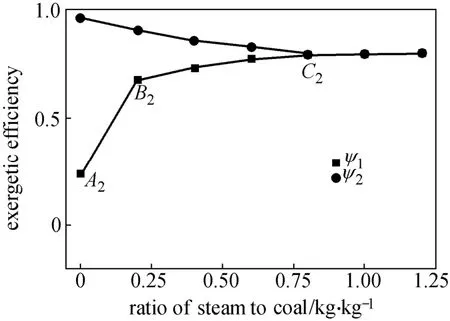
Figure 7 Effect of steam/coal ratio on exergy efficiency ψ1and ψ2
5 CONCLUSIONS
A steady state restricted equilibrium model is developed for a commercial-scale Lurgi fixed-bed gasifier and its thermodynamic performance is also investigated. The major contributions of this work include the utilization of GAMS to solve a non-linear programming (NLP) formulation developed for fitting experimental information for the pyrolysis reaction and the use of a multi-stage model with restricted equilibrium temperature to determine how many RGibbs blocks are needed in the gasification zone ofthe fixed-bed gasifier. The process model comprises four main parts: (1) coal drying in drying zone, (2) coal pyrolysis process in pyrolysis zone, (3) partial oxidation reaction in combustion zone, and (4) gas-solid reactions in gasification zone.
As noted above, the stoichiometric-based NLP formulation of the pyrolysis process is used to predict the composition of volatile products in the fixed-bed gasifier. Using the typical coal pyrolysis data and composition of distillable liquids, this NLP formulation does not require detailed information about the gasifier type, coal rank as well as operational temperature/ pressure. A four-stage Aspen Plus RGibbs model with restricted equilibrium temperature is then developed to study the thermodynamic equilibrium characteristics and calculate the composition of syngas in the combustion and gasification zones. Note that the restricted equilibrium temperature reported in public literature is mainly dependent on the coal gasifier type and the associated syngas cooling system.
Model predictions generally agree with industrial data. The model is used to perform comprehensive thermodynamic analysis by evaluating the effects of two important operating parameters, namely oxygen/coal ratio and steam/coal ratio. For a given coal feed rate, the exergetic efficiency is mainly determined by the oxygen/coal ratio and to a lesser extent by the steam/coal ratio. Under given conditions of reactor pressure (4.04×10⁶Pa) and coal feed rate (40 t·h−1), the exergetic efficiency reaches a value of 78.3% at oxygen/coal and steam/coal mass ratios of 0.14 and 0.80, respectively.
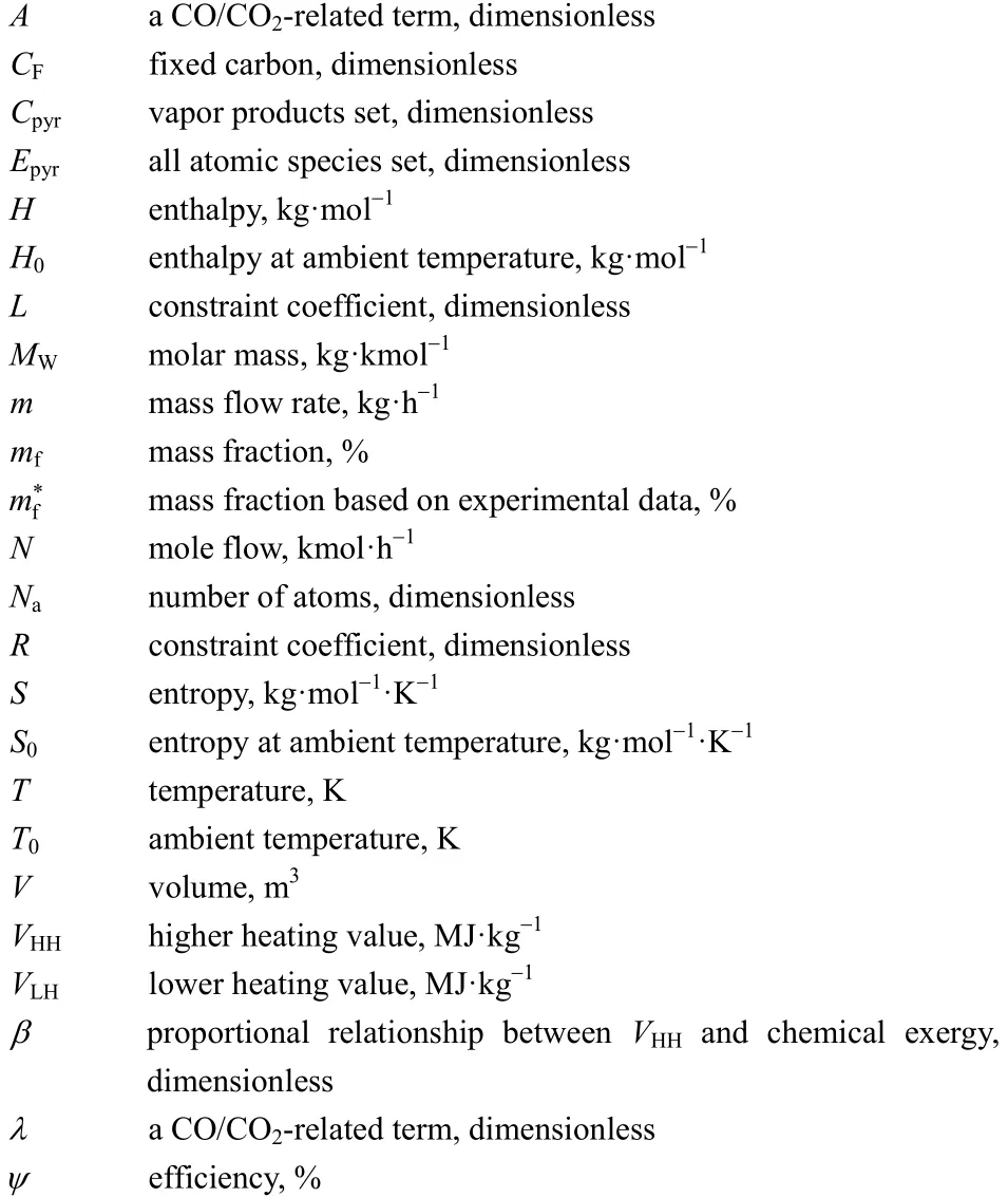
NOMENCLATURE

REFERENCES
1 “International Energy Outlook 2011”, U.S. Energy Information Administration, DOE/EIA-0484, 2011 [2014-01-20], http://www.eia.gov/ pressroom/presentations/howard_09192011.pdf.
2 Ma, L., Liu, P., Fu, F., Li, Z., “Integrated energy strategy for the sustainable development of China”, Energy, 36, 1143-1154 (2011).
3 Emun, F., Gadalla, M., Majozi, T., Boer, D., “Integrated gasification combined cycle (IGCC) process simulation and optimization”, Comput. Chem. Eng., 34, 331-338 (2010).
4 Pérez, F.M., Bojarski, A.D., Velo, E., Puigjaner, L., “Conceptual model and evaluation of generated power and emissions in an IGCC plant”, Energy, 34, 1721-1732 (2009).
5 Zhou, L., Hu, S., Li, Y., Zhou, J.H., “Study on co-feed and co-production system based on coal and natural gas for producing DME and electricity”, Chem. Eng. J., 136, 31-40 (2008).
6 He, C., Feng, X., “Evaluation indicators for energy-chemical systems with multi-feed and multi-product”, Energy, 43, 344-354 (2012).
7 Barker, R.E., Begovich, J.M., Clinton, J.H., “ASPEN modeling of the tri-state indirect- liquefaction process”, Oak Ridge National Laboratory, ORNL/TM-86 (1983).
8 Yan, H.M., Rudolph, V., “Modeling a compartmented fluidized bed coal gasifier process using ASPEN Plus”, Chem. Eng. Commun., 183, 1-38 (2000).
9 Liu, Z., Fang,Y., Deng, S., Huang, J., Zhao, J., Cheng, Z., “Simulation of pressurized ash agglomerating fluidized bed gasifier using ASPEN PLUS”, Energ. Fuel., 26, 1237-1245 (2011).
10 Yan, L., He, B., Ma, L., Pei, X., Wang, C., Li, X., “Integrated characteristics and performance of zero emission coal system”, Int. J. Hydrogen Energ., 37, 9669-9676 (2012).
11 Hobbs, M.L., Radulovic, P.T., Smoot, L.D., “Modeling fixed-bed coal gasifiers”, AIChE J., 38, 681-702 (1992).
12 Li, F., Zeng, L., Velazquez-Vargas, L.G., Yoscovits, Z., Fan, L.S.,“Syngas chemical looping gasification process: Bench-scale studies and reactor simulations”, AIChE J., 56, 2186-2199 (2010).
13 Li, F., Zeng, L., Fan, L.S., “Biomass direct chemical looping process: Process simulation”, Fuel, 89, 3773-3784 (2010).
14 Bhattacharyya, D., Turton, R., Zitney, S.E., “Steady-state simulation and optimization of an integrated gasification combined cycle power plant with CO2capture”, Ind. Eng. Chem. Res., 50, 1674-1690 (2011).
15 Juraščík, M., Sues, A., Ptasinski, K.J., “Exergy analysis of synthetic natural gas production method from biomass”, Energy, 35, 880-888 (2010).
16 Prins, M.J., Ptasinski, K.J., Janssen, F.J.J.G, “From coal to biomass gasification: Comparison of thermodynamic efficiency”, Energy, 32, 1248-1259 (2007).
17 Ngo, S.I., Nguyen, T.D.B., Lim, Y.I., Song, B.H., Lee, U.D., Choi, Y.T., Song, J.H., “Performance evaluation for dual circulating fluidized-bed steam gasifier of biomass using quasi-equilibrium three-stage gasification model”, Appl. Energ., 88, 5208-5220 (2011). 18 Ptasinski, K.J., Prins, M.J., Pierik, A., “Exergetic evaluation of biomass gasification”, Energy, 32, 568-574 (2007).
19 He, C., Feng, X., Chu, K.H., “Process modeling and thermodynamicanalysis of Lurgi fixed-bed coal gasifier in an SNG plant”, Appl. Energ., 111, 742-757 (2013).
20 Duret, A., Friedli, C., Maréchal, F., “Process design of Synthetic Natural Gas (SNG) production using wood gasification”, J. Clean. Prod., 13, 1434-1446 (2005).
21 Doherty, W., Reynolds, A., Kennedy, D., “The effect of air preheating in a biomass CFB gasifier using ASPEN Plus simulation”, Biomass Bioenerg., 33, 1158-1167 (2009).
22 Zhang, Y., Xiao, J., Shen, L., “Simulation of methanol production from biomass gasification in interconnected fluidized beds”, Ind. Eng. Chem. Res., 48, 5351-5359 (2009).
23 Nikoo, M.B., Mahinpey, N., “Simulation of biomass gasification in fluidized bed reactor using ASPEN PLUS”, Biomass Bioenerg., 32, 1245-1254 (2008).
24 Ramzan, N., Ashraf A., Naveed S., Malik, A., “Simulation of hybrid biomass gasification using Aspen Plus: A comparative performance analysis for food, municipal solid and poultry waste”, Biomass Bioenerg., 35, 3962-3969 (2011).
25 Yoon, H., Wei, J., Denn M.M., “A model for moving-bed coal gasification reactors”, AIChE J., 24, 885-903 (1978).
26 Adanez, J., Labiano, F.G., “Modeling of moving-bed coal gasifiers”, Ind. Eng. Chem. Res., 29, 2079-2088 (1990).
27 Baliban, R.C., Elia, J.A., Floudas, C.A., “Toward novel hybrid biomass, coal, and natural gas processes for satisfying current transportation fuel demands (1) Process alternatives, gasification modeling, process simulation, and economic analysis”, Ind. Eng. Chem. Res., 49, 7343-7370 (2010).
28 Suuberg, E.M., Peters, W.A., Howard, J.B., “Product composition and kinetics of lignite pyrolysis”, Ind. Eng. Chem. Proc. Des. Dev., 17, 37-46 (1978).
29 Stefano, J.M., “Evaluation and modification of ASPEN fixed-bed gasifier models for inclusion in an integrated gasification combined-cycle power plant simulation”, U.S. Department of Energy Office of Fossil Energy, DE/85013693 (1985).
30 Janajreh, I., Raza, S.S., Valmundsson, A.S., “Plasma gasification process: Modeling, simulation and comparison with conventional air gasification”, Energ. Convers. Manage., 65, 801-809 (2013).
31 Tay, D.H.S., Ng, D.K.S., Kheireddine, H., El-Halwagi, M.M., “Synthesis of an integrated biorefinery via the C HO ternary diagram”, Clean Technol. Environ. Policy, 13, 567-579 (2011).
2012-10-15, accepted 2013-08-03.
* Supported by the National Basic Research Program of China (2012CB720500) and the National Natural Science Foundation of China (U1162121).
** To whom correspondence should be addressed. E-mail: xfeng@cup.edu.cn
 Chinese Journal of Chemical Engineering2014年5期
- Chinese Journal of Chemical Engineering的其它文章
- Effect of Adsorbent Diameter on the Performance of Adsorption Refrigeration*
- Filtering Surface Water with a Polyurethane-based Hollow Fiber Membrane: Effects of Operating Pressure on Membrane Fouling*
- A Facile Route for Synthesis of LiFePO4/C Cathode Material with Nano-sized Primary Particles*
- High-Thermal Conductive Coating Used on Metal Heat Exchanger*
- Kinetics of Forward Extraction of Boric Acid from Salt Lake Brine by 2-Ethyl-1,3-hexanediol in Toluene Using Single Drop Technique*
- Soft Sensor Model Derived from Wiener Model Structure: Modeling and Identification*