
A Contraction-expansion Helical Mixer in the Laminar Regime*
2014-07-24 15:40LIANGDongandZHANGShufen张淑芬
关键词:淑芬
LIANG Dong (梁 栋) and ZHANG Shufen (张淑芬)
State Key Laboratory of Fine Chemicals, Dalian University of Technology, Dalian 116024, China
A Contraction-expansion Helical Mixer in the Laminar Regime*
LIANG Dong (梁 栋) and ZHANG Shufen (张淑芬)**
State Key Laboratory of Fine Chemicals, Dalian University of Technology, Dalian 116024, China
A contraction-expansion helical mixer which combines several features, viz. helical pipes for induction of secondary flows and sudden expansion and contraction array for expansion vortices, has been designed to enhance flow mixing. A fast competitive-consecutive diazo coupling reaction is used to test the mixing efficiency of contraction-expansion helical mixer. Furthermore, an image processing technique is applied for data visualization and monitoring the extent of mixing. The mixing performance is found to be superior in comparison to the regular helical mixer in the range of Reynolds number from 170 to 1540. Moreover, the mixing time of contraction-expansion helical mixer was found to be reduced by more than 25% compared to the regular helical pipe. Finally, a simple correlation is proposed for predicting the mixing time.
contraction-expansion, helical pipe, mixing, laminar flow
1 INTRODUCTION
Over the past decade, many investigations are dedicated to enhancing mixing in order to minimize the temperature gradients in heating systems or to increasing the conversion rate of chemical reaction in continuous processes [1]. Techniques commonly used to enhance mixing involve the generation of a turbulent flow; but the main drawback of which is energy consumption by turbulent agitation [2]. While it is very difficult to reach the turbulent flow regime in a conduit of small dimension, laminar flow is usually encountered. In the laminar flow regime, mixing mainly relies on diffusive mass transfer in a straight pipe, which is very slow. So the mixing channel has to be extremely long for practical applications.
Several passive mixers have been developed and studied to enhance mixing over the purely diffusive limit in the laminar regime, such as “split-and-recombine”mixer and advection mixer. Split-and-recombine mixers [3, 4] employ typically three-dimensional channels to split, redirect, and recombine fluid streams. These structures are not very efficient in time or in space. Usually a very long channel is needed to allow molecular diffusion to complete mixing. Advection mixers exploit the large-scale motion of fluid current in a mixer. It can be categorized into either chaotic mixers or Dean mixers.
Chaotic mixers [5-9] passively generate a transversal component of velocity that expand continuously the interfacial area between species through stretching or folding process, thereby stirring the boundary layer and enhancing mixing in channels. This chaotic flow can be generated in the channel which is embedded with barriers allocated periodically [10] or patterned with a series of diagonal ridges [11]. Both of these systems show promise as mixers, while the small features within the channels makes the mixer manufacture very complex [12].
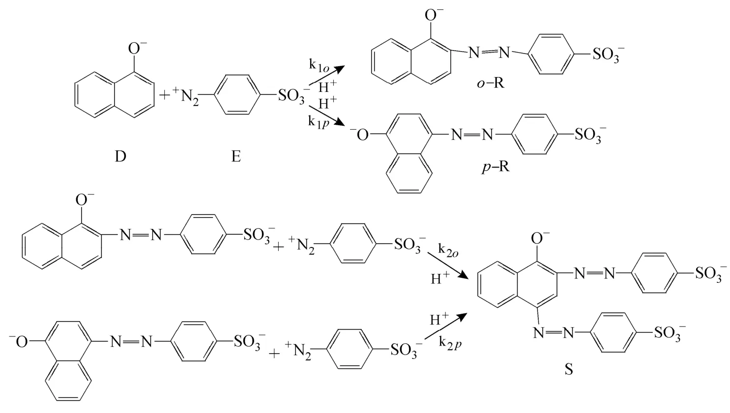
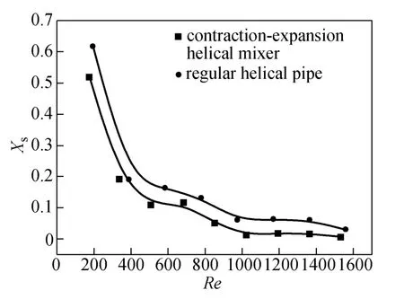
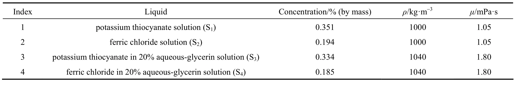
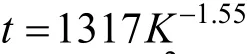
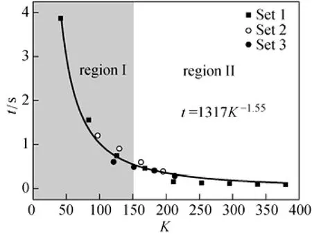
Dean mixers [13-16] exploit transverse secondary flows (Dean flow) which arise as a result of the interplay between centrifugal forces and viscous forces in helical pipes. For helical systems, curvature amplifies a lateral instability that drives a secondary cross-channel flow and increases transverse mixing. Erdogan and Chatwin [17] carried out a theoretical analysis of the effective dispersion in a helical pipe and concluded that the secondary flow increases transverse mixing and makes concentration distribution in the cross-sectional plane more uniform compared with that obtained in a straight tube. Trivedi and Vasudeva [18] reported an experimental study on Reynolds number region (5.2 In planar helical channels, mixing could be improved efficiently by the presence of either sudden expansion or contraction configurations which changed the cross sectional area abruptly. By employing geometries that combine planar helical micro-channels and expansion units, Sudarsan and Ugaz verified that even for low Re region (0.02 Therefore, in this work, we design a contraction-expansion helical mixer which comprises sudden expansion and contraction array. The proposed mixer design utilizes both expansion vortices that are due toan abrupt increase in cross-sectional area and Dean vortices that arise in the helical pipes, thereby enabling appreciable mixing. The aim of present work is to investigate the mixing efficiency of this new contraction-expansion helical mixer over a wide range of flow conditions (170 Figure 1 (a) The sketch of the mixer, (b) experimental flow chart and (c) digital color images of the mixture along the flow path 2.1 Experimental principle In curved tube, transverse secondary flows (Dean flow) arise. The centrifugal effects induce a secondary flow field characterized by the presence of two counter-rotating vortices located above and below the plane of symmetry of the channel, coinciding with its plane of curvature. The magnitude of these effects is characterized by the dimensionless Dean number K′=δ0.5Re, where δ is the ratio of the channel hydrodynamic radius to the flow path radius of curvature, Re=Ud/ν, where U is the average flow velocity, d is the hydraulic diameter which is calculated based on the volume (V) and wetted surface area (Awet) as d=4V/Awet, and ν is the kinematic viscosity of the fluid. In helical pipe, the so-called modified Dean number (K) can be used in order to take into account the pitch (b) effect [22]: where Dcdenotes the effective coil diameter which varies as a function of (b) pitch of the coil, and D is the coil diameter (m). 2.2 Fabrication of contraction-expansion helical mixer The experimental setup is illustrated in Fig. 1 (b). It consists of the contraction-expansion helical mixer, two continuously working precision double-plunger micro pumps (HLB-100/10, Yanshan Meter General Factory, Dongtai, Jiangsu, China), a digital camera (IXUS 120, Cannon) and a computer for data acquisition. A scaled-up sketch of the contraction-expansion helical mixer structure described in Fig. 1 (a) was realized by transparent polyurethane (PU) pipe. The contraction-expansion helical mixer comprises 20 identical mixing elements that consist of 20 thinner pipes (10.5 mm radius of curvature) having 2 mm inner diameter [blue pipe in Fig. 1 (a)] and 20 thicker pipes (10.5 mm radius of curvature) having 3 mm inner diameter [green pipe in Fig. 1 (a)]. Thinner pipes and thicker pipes were connected by a sudden expansion or a sudden contraction alternatively. The total length of tested conduit is 2 m. Fig. 1 (c) illustrates the digital color images of the mixture along the flow path at loops 1 to 6 of the contraction-expansion helical mixer for determining the mixing extent under the condition of Re=342. 2.3 Micromixing experiment In comparison between mixers with regard to mixing performance, a homogeneous competitive-consecutive reaction between 1-naphthol (D, c=3.6×10⁻³mol·L−1) and diazotized sulfanilic acid (E, c=3.6×10⁻³mol·L−1) was used to quantify mixing efficiency. The reactions occurred can be described as follows [23]: where k1o≫k2o; k1p≫k2p. At ambient pressure and temperature conditions (25 °C), k1o=920, k1p=12240, k2o=1.84, and k2p=22, all in unit of mol·m−3·s−1. Thus, the first reaction is some 3 orders of magnitude faster than the second one. Diazotized sulphanilic acid is common to both reactions and, when present in limiting quantity, makes the reaction set sensitive to mixing. The product distribution (XS) was given by in which cs, co-Rand cp-Rare the concentrations measured spectrophotometrically at the end of the reaction coil. It has been confirmed that cB=0 at the coil exit is well guaranteed. In an ideally (perfectly) mixed environment the products are kinetically controlled. Since the first reaction is much faster than the other (k1≫k2), little or no product S will be formed, i.e., XSapproaches 0. While, in any real system, XSis greater than 0. The value of XScan be taken as an indication of mixing efficiency: the lower XSmeans better mixing [24]. 2.4 Mixing extent experiment In this study, we visualized the mixing process by employing a very fast ionic dye reaction, that is, aqueous solutions of iron(III) chloride (c=0.012 mol·L−1, light brown color) and potassium rhodanide (c=0.012 mol·L−1, colorless), which formed the intense reddish Fe(III) rhodanide after a 1︰1 stoichiometric reaction. The extent of mixing was determined by the amount of red color that was generated when the two streams are mixed. The digital images were imported into custommade software (Matlab) to extract red color intensity and the images were converted to gray-scale. Mixing extent (IM) was then calculated using the following equation [25]: The homogeneous mixture was prepared in advance and its image was taken at the first loop. For the calculation of mixing extent [26], the gray scale of 0 corresponds originally to black and 255 to white. In the present system, the average gray scale of image of the completely mixed homogeneous mixture was 56 (corresponding to the mixing extent IM=1), and the average gray scale of background liquids [total effect of iron(Ⅲ) chloride and potassium rhodanide solutions before mixing] was 251 (before mixing, IM=0). Therefore, the read-out grayness values should be rescaled to match the full span of IMfrom 0 to 1. As shown in Fig. 2 (b), the mixing extent of the non-homogeneous mixture at the first loop of the contraction-expansion helical mixer is equal to 0.81 (the read-out grayness of 93) for Re=342. Figure 2 Color image standard before mixing of two solutions (superimposition of their respective images taken 5 cm downstream the inlet at the first loop end) and its corresponding gray scale image for Re=342, digital color image and corresponding gray scale image of the homogeneous mixture for Re=342 and resulting gray scale and mixing extent for (1b) and (2b) Additionally, the light intensity was kept constant to avoid any color changes throughout the experiments. The mixing length is defined as the coil length from the initial confluence to a position with IM=0.95. The mixing time was then calculated by dividing the mixing length by the corresponding mean liquid velocity. All the experiments were carried out under conditions of ambient pressure and temperature (25±1 °C). The two miscible liquid streams with equal volumetric flows rates flowed through the two horizontal branches of a Y-shaped channel whose angle was 60°, then entered the main mixing unit. The flow rates ranged from 10 to 90 ml·min−1were adjusted by the precision doubleplunger micro pumps. Accuracy measurements of the mass-flow affirmed an error of about 3% at worst in the flow-range. The corresponding Dean numbers tested ranged from 42 to 384. 3.1 Comparison of mixing performance In order to investigate the effect of the Reynolds number on the mixing performance, volumetric flow rate of D (solution of 1-naphthol) and E (solution of diazotized sulfanilic acid) should be varied. The Reynolds number in our research is in the range of 107-1540 (corresponding to U=0.08 to 0.69 m·s−1, the residence time t=25 to 2.90 s) and the flow in the outlet channel is laminar. Fig. 3 shows experimental results in the first type of mixing experiment for contraction-expansion helical mixer as compared to regular helical pipe with the same length (2 m). Figure 3 XSversus Re for contraction-expansion helical mixer and regular helical pipe (2 mm inner diameter) Figure 4 Non-averaged mixing extent for the first region (pipe length=5 cm) in (a) regular helical pipe, (b) contraction-expansion helical mixer (X axis: the direction of flow; Y axis: perpendicular to the flow direction), (c) average mixing extent changes along the flow direction of regular helical pipe and contraction-expansion helical mixer Table 1 Physical properties of the liquids used It can be seen that for Re in the range of 170 to 1540, XSdeclined with the increase of Re, and XSin contraction-expansion helical mixer was smaller than that in regular helical pipe. As mentioned above, additional geometrical structure enhance the stretching and folding of the flow element and thus promotes fluid mixing, so the contraction-expansion helical mixer provided better mixing performance than regular helical pipe. It also should be noted that the measured values of XSwere about 0.01 and independent of Reynolds number when Re was large than 1000 in contractionexpansion helical mixer. Plotted in Fig. 4 (a) and 4 (b) are the nonaveraged mixing extent in the first region along the flow direction for the two pipes, contraction-expansion helical mixer and regular helical pipe at Re=170. As can be seen, the maximum value changed from region A in regular helical pipe [Fig. 4 (a)] to regions B and C in contraction-expansion helical mixer [Fig. 4 (b)]. The second observation is that the magnitude of the maximum value in contraction-expansion helical mixer was larger than that in regular helical pipe due to the presence of sudden expansion and contraction array lead to enhanced heterogeneity in the lateral flow field. Plots in Fig. 4 (c) are the average mixing extent, based on Eq. (4), along the flow direction for the two mixers, contraction-expansion helical mixer and regular helical pipe at Re=170. As shown in Fig. 4 (c), the mixing extent in contraction-expansion helical mixer is larger than that in regular helical pipe at the same pipe length. 3.2 Comparison of mixing time The mobility of a solute in solution depends heavily upon the diffusivity of solute and the viscosity of the solution, which directly affects the mixing of fluids [26]. We investigated the mixing behavior of fluids with different viscosities as shown in Tables 1 and 2. Table 2 Plan of experiment Figure 5 Mixing time vs. average velocity U for all sets used in contraction-expansion helical mixer and regular helical pipe Quantitative results for viscous fluid mixing in the devices are shown in Fig. 5. It is obvious that mixing time in contraction-expansion helical mixer is shorter than that in regular helical pipe for the same experiment set. In contraction-expansion helical mixer, the average mixing time reduced by 51.8%, 37.3% and 25.3% compared with that in regular helical pipe for the three experimental sets, respectively. When the viscosity of fluids increased from 1.05 to 1.80 mPa⋅s (Set 1 to Set 3), the mixing time increased from 0.12 to 0.39 s for the contraction-expansion helical mixer, and from 0.30 to 0.65 s for the regular helical pipe at a velocity 0.51 m·s−1, reflecting that the increment of liquid viscosity certainly weakened the mixing ability of the mixers. It also can be seen that mixing time is affected primarily by the differences in viscosities between the two fluids rather than the viscosity of the mixture (Table 2) in the same mixer. The longest mixing time is required in Set 2 which has the largest viscosity difference, i.e., 0.75 mPa⋅s. The dependence of mixing time t on Dean number K for all sets used in contraction-expansion helical mixer is shown in Fig. 6. Reynolds and Dean numbers are calculated using the physical parameters of the resultant homogeneous mixture (Table 2). The plot can be easily divided into two regions. In region I where K values is lower than 150, the mixing time drastically decrease with increasing K values, while in region II the mixing time tends to an almost constant value regardless of the values of K. The results are also in agreement with the findings of the previous studies [27, 28], which are attributed to the appearance of two additional counter-rotating Dean vortices at these K values. The results of the present study are well correlated by a power law function: which is highly significant (R2=0.9903). Figure 6 Mixing time with respect to Dean number for all sets used in contraction-expansion helical mixer A novel contraction-expansion helical mixer, consisting of short helical pipes of 2 mm inner diameter and having a sudden expansion and contraction array, was designed and experimentally tested. For Dean numbers in the range of 30 to 370, the mixing performance in contraction-expansion helical mixer was found to be better than that in regular helical pipe. The introduction of geometrical structure considerably promoted fluid mixing, leading to a substantial reduction in mixing time. For instance, the mixing time of contraction-expansion helical mixer was found to be reduced by more than 25% compared to the regular helical pipe for reaction between solutions of iron(Ⅲ) chloride and potassium rhodanide. Moreover, the mixing time was described by a simple power law which is valuable information for the design of application-specific mixers. NOMENCLATURE Awetwetted surface area, m2 B pitch of the coil, (=0.005), m c amount of substance concentration, mol·L−1 D coil diameter, m Dceffective coil diameter defined by Eq. (2), m d inner diameter of pipe, m IMmixing extent defined by Eq. (4) k reaction rate constants, mol·m−3·s−1 o-R 2-[(4-sulfophenyl)azo]-1-naphthol p-R 4-[(4-sulfophenyl]azo]-1-naphthol Re Reynolds number (=ρUd/μ) S 2,4-bis[(4-sulfophenyl)azo]-1-naphthol t mixing time, s U average flow velocity, m·s−1 V volume, m3 XSproduct distribution δ the ratio of the channel hydrodynamic radius to the flow path radius of curvature μ dynamic viscosity, Pa·s ν kinematic viscosity, m2·s−1 ρ density, kg·m−3 REFERENCES 1 Castelain, C., Legentilhomme, P., “Residence time distribution of a purely viscous non-Newtonian fluid in helically coiled or spatially chaotic flows”, Chem. Eng. J., 120 (3), 181-191 (2006). 2 Castelain, C., Mokrani, A., Legentilhomme, P., Peerhossaini, H.,“Residence time distribution in twisted pipe flows: Helically coiled system and chaotic system”, Eχp. Fluids, 22 (5), 359-368 (1997). 3 Bessoth, F.G., Andrew, J.M., Manz, A., “Microstructure for efficient continuous flow mixing”, Anal. Commun., 36 (6), 213-215 (1999). 4 Mansur, E.A., Ye, M.X., Wang, Y.D., Dai, Y.Y. “A state-of-the-art review of mixing in microfluidic mixers”, Chin. J. Chem. Eng., 16 (4), 503-516 (2008). 5 Mengeaud, V., Josserand, J., Girault, H.H., “Mixing processes in a zigzag microchannel: Finite element simulations and optical study”, Anal. Chem., 74 (16), 4279-4286 (2002). 6 Nguyen, N.T., Wu, Z.G., “Micromixers—A review”, J. Micromech. Microeng., 15 (2), R1-R16 (2005). 7 Wiggins, S., Ottino, J.M., “Foundations of chaotic mixing”, Phil. Trans. R. Soc. Lond. A, 362, 937-970 (2004). 8 Fan, Y.R., Lu, Z.M., “Non-Newtionian effects on chaotic mixing between eccentric cylinders”, Chin. J. Chem. Eng., 9 (3), 306-309 (2001). 9 Wang, L.X., Chen, Y., Fan, Y.R., Lu, Y.X., “Numerical investigation on mixing efficiency and exponential fluid stretching in chaotic mixing”, Chin. J. Chem. Eng., 8 (3), 203-207 (2000). 10 Wang, R.J., Lin, J.Z., Li, H.J., “Chaotic mixing on a micromixer with barriers embedded”, Chaos Solitons Fractals, 33, 1362-1366 (2007). 11 Stroock, A.D., Dertinger, S.K.W., “Chaotic mixer for microchannels”, Science, 295, 647 (2002). 12 Howell Jr, P.B., Mott, D.R., Golden, J.P., Ligler, F.S., “Design and evaluation of a Dean vortex-based micromixer”, Lab Chip, 4 (6), 663-669 (2004). 13 Trivedi, R.N., Vasudeva, K., “Axial dispersion in laminar flow in helical coils”, Chem. Eng. Sci., 30 (3), 317-325 (1975). 14 Wang, R.J., Lin, J.Z., “Numerical analysis on a passive chaotic micromixer with helical microchannel”, J. Nanosci. Nanotechnol., 6 (1), 190-194 (2006). 15 Daskopoulos, P., Lenhoff, A.M., “Dispersion coefficient for laminar flow in curved tubes”, AIChE. J., 34 (12), 2052-2058 (1988). 16 Vanka, S.P., Luo, G., Winkler, C.M., “Numerical study of scalar mixing in curved channels at low Reynolds numbers”, AIChE J., 50 (10), 2359-2368 (2004). 17 Erdogan, M.E. Chatwin, P.C., “The effects of curvature and buoyancy on the laminar dispersion of solute in a horizontal tube”, J. Fluid Mech., 29 (3), 465-484 (1967). 18 Trivedi, R.N., Vasudeva, K., “RTD for diffusion-free laminar flow in helical coil”, Chem. Eng. Sci., 29 (12), 2291-2295 (1974). 19 Yamagishi, A., Inaba, T., Yamaguchi, Y., “Chaotic analysis of mixing enhancement in steady laminar flows through multiple pipe bends”, Int. J. Heat Mass Transfer, 50 (7-8), 1238-1247 (2007). 20 Sudarsan, A.P., Ugaz, V.M., “Fluid mixing in planar spiral microchannels”, Lab Chip, 6 (1), 74-82 (2006). 21 Sudarsan, A.P., Ugaz, V.M., “Multivortex micromixing”, Proc. Natl. Acad. Sci., 103 (19), 7228-7233 (2006). 22 Kuakuvi, D.N., Moulin, P., Charbit, F., “Dean vortices: A comparison of woven versus helical and straight hollow fiber membrane modules”, J. Memb. Sci., 171 (1), 59-65 (2000). 23 Bourne, J.R., Maire, H., “Micromixing and fast chemical reactions in static mixers”, Chem. Eng. Process., 30 (1), 23-30 (1991). 24 Akiti, O., Armenante, P.M., “Experimentally-validated micromixing based CFD model for fed-batch stirred-tank reactors”, AIChE J., 50 (3), 566-577 (2004). 25 Hessel, V., Löwe, H., Schönfeld, F., “Micromixers—A review on passive and active mixing principles”, Chem. Eng. Sci., 60 (8), 2479-2501 (2005). 26 Fang, W.F., Yang, J.T., “A novel microreactor with 3D rotating flow to boost fluid reaction and mixing of viscous fluid”, Sens. Actuators, B, 140 (2), 629-642 (2009). 27 Baier, T., Drese, K.S., Schönfeld, F., Schwab, U., “A μ-fluidic mixing network”, Chem. Eng. Technol., 28 (3), 362-366 (2005). 28 Jiang, F., Drese, K.S., Hardt, S., Küpper, M., Schönfeld, F., “Helical flows and chaotic mixing in curved micro channels”, AIChE J., 50 (9), 2297-2305 (2004). FLUID DYNAMICS AND TRANSPORT PHENOMENA Chinese Journal of Chemical Engineering, 22(3) 261—266 (2014) 10.1016/S1004-9541(14)60035-5 2012-05-22, accepted 2013-04-10. *Supported by the National Key Technology R&D Program (2011BAE07B01) and the National Natural Science Foundation of China (20836001). **To whom correspondence should be addressed. E-mail: zhangshf@dlut.edu.cn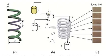
2 EXPERIMENTAL


3 RESULTS AND DISCUSSION


4 CONCLUSIONS
猜你喜欢
金山(2022年11期)2022-12-03中国民间疗法(2021年16期)2021-11-04意林·少年版(2019年21期)2019-12-17小读者·阅世界(2019年7期)2019-09-10小天使·一年级语数英综合(2018年12期)2018-11-19小天使·一年级语数英综合(2018年9期)2018-10-16小天使·一年级语数英综合(2018年10期)2018-10-16妇女生活(2018年10期)2018-10-12数学大王·低年级(2018年12期)2018-01-10党的生活(黑龙江)(2014年9期)2014-09-28
 Chinese Journal of Chemical Engineering2014年3期