
A class of piecewise dissipative control of steam generator water level
2014-08-05 06:46WANGJunlingLIFeifeiLIJie
哈尔滨商业大学学报(自然科学版) 2014年5期
WANG Jun-ling,LI Fei-fei,LI Jie
(School of Nuclear Science and Technology,Harbin Engineering University,Harbin 150001,China)
Steam generator(SG)is one of the most important equipment in a nuclear power plant.The role of a SG is to transfer the energy from the reactor coolant system in the primary side to the secondary side,and to create the steam that will drive the turbines.It is of significance for nuclear reactor normal operation to maintain SG’s safety and reliability.So the SG water level must be regulated in the reasonable range.Its highly non-linearity,strong disturbance and nonminimum phase behaviors make it difficult to design a desirable controller for water level control.At present,PID type controllers are still preponderating in SG water level control[1].With the development of computer technology and control theory,many methodologies,such as model predictive control,adaptive control,neural networks control and fuzzy control,have been applied to the water-level control of SG[2-5].Though the advanced controllers introduced above have provided good performance,the simple control structures and satisfactory control schemes are still very scarce.
The notion of dissipation introduced by Willems in 1972 is a system theoretic concept that comes from physical reality and considers the energy of the physical system[6].This notion states that the energy increase in the system over a time interval cannot exceed the energy that is supplied to the system during this time-interval.It means that the system loses energy over time and eventually the system must grind to a stop and reach some final stable state.Therefore,dissipation has a strong connection with system stability and it plays an important role in the systems stability analysis and design.Recently,many researchers have studied the theory of dissipation and applied it to the permanent magnet synchronous motors system,the nuclear heating reactor load-following system,and the SG water level control system[7].
In this paper the problem of quadratic dissipative control for SG water level control system has been taken into account.Firstly,based on simplified model that Irving put forward,the linear parameter varying(LPV)model of SG is built.Secondly,a state feedback dissipative controller(SFDC)with a mixed H∞and positive real performance is designed.Thirdly,a modified control strategy,piecewise dual- controller(PDC)is proposed,which consists of a SFDC and a PID controller.At last,the feasibility of the proposed framework is shown via simulation,and the latter one has better performance than the cascade PID control.
1 Mathematical model of SG
A SG is a dynamic complicated system with nonlinear characteristics.Based on the Irving’s SG model and LPV theory,the LPV SG water level control system can be constructed[8]as

where x(t)=[xT1(t)xT2(t)xT3(t)xT4(t)xT5(t)]Tis the state vector which contains the factors of changing the water level.u(t)denotes control input which means feed water flow in this system.qv(t),which is the exogenous input,denotes the deviation from initial value of steam flow.y(t)is the water level as a measured output.p means percentage of the operational and rated power values,and it determines the values of various system matrices(A(p),B1(p)).The Irving’s model is divided into four regions:5% ~15%,15% ~30%,30% ~50%,50% ~100%.The parameters of the Irving’s model are presented in Table 1.Because the model is assumed to be LPV in each region,so the rest of the working points of the model parameters can be obtained by linear interpolation.

(p),a22= -τ-12(p),a25= -G2(p)/τ2(p),a33= -2τ-11(p),a35=G3(p),a43= - τ(p)-4π2T-2(p),a55= -1,b11= -G1(p),b12=G2(p)/τ2(p)

Table1 Parameters of a SG
2 Dissipative control methodology
The system(1)is dissipative with respect to the supply rate s(u(t),y(t)),if satisfies:
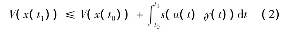
with V(x)is a non-negative storage function,s(u(t),y(t))is the supply rate function.From(2),it is concluded that when t>0,V(x(t1))is less than or equal to the sum of the initial time storage energy V(x(t0))and the supply of energy from outside in time- interval[t0,t1].Namely,the system does not produce energy,except the energy dissipation.
Considering the system(1),the quadratic energy supply function E(qv(t),z(t),T)is given as follows:

When Q= - I,S=0,R= γ2I,the strict(Q,S,R)dissipation reduces to a H∞norm constraint.
When,Q=0,S=I,R=0,the strict(Q,S,R)dissipation reduces to strict positive realness.
When,Q= - θI,S=(1 - θ),R= θγ2I,θ∈(0,1),the strict(Q,S,R)dissipation represents a mixed H∞and positive real performance.
Definition 1[9]:Under zero initial condition,when u(t)=0,T >0 ,for some scalar α >0,the system(1)is regarded as strict(Q,S,R)dissipation,if satisfies:
E(qv(t),z(t),T)≥α〈qv(t),qv(t)〉T
For the system(1),there exists a state feedback control,

where K is the controller gain matrix.
Then,the resulting closed-loop system is described as

Lemma 1[10]:Let Q,S and R be given matrices with Q and R symmetric.Consider the system(1)subject to:

there exists a control law(4)such that the resulting closed-loop system(5)is asymptotically stable and strictly(Q,S,R)dissipative if and only if there exist matrices X>0 and Y,satisfying the following linear matrix inequality(LMI):

moreover,a suitable control law is given by K=YX-1.
3 Piecewise SFDC design and numerical simulation
The gain scheduling based on the LPV model is used as follows:①the whole operating range is divided in four regions;②a SFDC is designed for each region;③at any time,qv(t)is used to identify the SG operating power according to Table 1 and the operating range can be judged;④based on the identified region,a proper controller is selected.During solving controller for each region,the coefficient matrices of each integer power are obtained by using linear inter-polation.Then,each of them satisfies Lemma 1.By solving the set of linear matrix inequalities obtained in the Lemma 1,the controller of each region can be gained finally.

Figure1 Response of water level at 5%power

Figure2 Response of water level at 15%power

Figure3 Response of water level at 30%power

Figure4 Response of water level at 50%power

Figure5 Response of water level at 100%power
Specifically,taking region as an example,the power points are chosen as follows:5%,6%,7%,8%,9%,10%,11%,12%,13%,14%and 15%.According to the known coefficient matrices in 5%and 15%power point of Irving’s model,the rest of the model parameters at 9 different power points are obtained by interpolation based on the provided data.Then,making the LMI(6)corresponding to the 11 power points possess a common solution,the controller gain K can be obtained depending on Lemma 1 finally.
Considering Q= - θI ,S=(1 - θ)I,R= θγ2and setting θ=0.25,the SFDC in four regions can be derived conveniently from solving the four set of LMS.
Simulations are conducted to assess the controller’s performance.The simulating time is 400 s,steam flow rate produces 30 kg/s step-up at 100 s.The responses of the SG water level with respect to steam flow rate disturbance at 5%,15%,30%and 50%power points are depicted from Figure1 to Figure4.Figsure 5 shows the response of water level with 30 kg/s step-depress in steam flow rate at 100 s at power 100%.Figure6 illustrates the water level response for 5%per minute of rated power ramp-increase starting from 10%to 40%and a ramp-down from 40%to 10%.

Figure6 water level response to the power ranges linearly from 10%through 40%to 10%.(A)power trajectory(B)corresponding water level responses.

Figure7 Closed-loop structure using the PDC
Initially,small steam flow perturbations are introduced about stationary points at the five power points.Figure1~5 show that the SFDC has achieved good rejection performance in the presence of disturbance.The settling time and overshoot of the closedloop system are satisfactory,especially SFDC has short regulating time in low operating region.The supply rate function of SFDC includes disturbance,controlled output,coupling of disturbance and controlled output factors,namely,both phase and gain performance of the system are considered,all above enable the SFDC to provide a more flexible and less conservative design.Thereafter,the operating power produces linear change from 10%to 40%.Figure6 depicts the SFDC can handle a larger power range situation and the overshoot is in the permissible range.
However,the steady state error is observed in all power levels.This is because the supply rate in Definition 1 is a constant which is greater than 0,videlicet,the influence to controlled output by disturbance can just be limited in a certain range,and it cannot be eliminated.
4 PDC design and numerical simulation
In order to eliminate the steady state error in FDC,a PID controller is added to control water level deviation,the PDC system is constituted.The closed-loop structure is demonstrated in Figure7.
According to the engineering setting method,PID parameters are tuned.The gains of FDC which be used are same with the section 4.
To test if the proposed control system achieves good anti-jamming capability and set-point tracking,the steam flow rate is chosen as 30 kg/s stepup at 20 s,and the set point for the water level increases from 0 to 100 mm at 500 s.The performances of the PDC and the cascade PID controller at 5%,15%,30%and 50%power level are given in Figure8 ~11.In Figure.12,a step-depress(30 kg/s)in the steam flow rate occurs at 20 s,and the set-point of the water level suddenly depresses from 0 to 100 mm at 500 s at power 100%.
From Figure8 to 12,both the PDC and the cascade PID controller can guarantee the globally stability of the water level control system.Compared with the cascade PID,the PDC has a smaller overshoot and a little worse setting time when steam flow rate is disturbed as the five pictures demonstrated.On the other hand,the PDC has smaller overshoot except in the 5%operating power level,while the regulating time of PDC is close to the cascade PID’s in all power levels as setpoint changes.Through the above analysis,it can be concluded that the proposed PDC has better performance than the cascade PID.Besides,the biggest advantage of the PDC is that the oscillation frequency caused by the transient response is reduced effectively.Moreover,the problem of steady state error can be eliminated.This is due to adding an integral action.

Figure8 Response of water level at 5%power

Figure9 Response of water level at 15%power

Figure10 Response of water level at 30%power

Figure11 Response of water level at 50%power

Figure12 Response of water level at 100%power
The mean of the squared error(MSE)index is an efficient and feasible measurement in performance assessment.In this paper,for comparison the performance of the PDC with the previous proposed controllers-ACNFC and Auto-PID,MSE is used[11-12].The values of MSE for three controllers are given in Table 2.

Table2 MSE performance index
The performance index of the PDC is better than the Auto-PID in all power regions.Compared with ACNFC,the PDC has better performance at 5%,15%,30%and 50%power points and similar performance at 100%power point.
5 Conclusions
For nuclear power plants,the water level control is one of the key technologies for ensuring economic viability and safety.In this paper,a SFDC has been proposed and applied to the nuclear SG water level control system.And then,a PDC based on SFDC and PID controller is designed and compared with the cascade PID controller.The computer simulation results demonstrate the effectiveness of the two proposed controllers in all power levels.In comparison with the cascade PID controller,PDC shows a improvement in water set point tracking and an increased ability in anti-jamming.In particular,the PDC can efficiently decrease the oscillation frequency caused by the steam flow rate disturbance.
[1]GANG Z,WEI P,DAFA Z.Analysis of water level control methods for nuclear steam generator[J].Atomic Energy Science and Technology,2004,38:20-21.
[2]W WEI,JUNLING W,WEISHI H.Piecewise H∞control for water level of steam generator[J].Nuclear Power Engineering,2009,30(5):105-109.
[3]ELIASIA H,DAVILUA H,MENHAJ M B.Adaptive fuzzy model based predictive control of nuclear steam generators[J].Nuclear Engineering and Design,2007,237(6):668-676.
[4]M G N A,Auto-tuned PID controller using a model predictive control method for the steam generator water level[J].IEEE Transations on Nuclear Science,2001,48(5):1664-1671.
[5]MUNASINGHE S R,KIM M S,LEE J J.Adaptive neurofuzzy controller to regulate UTSG water level in nuclear plants[J].IEEE Transations on Nuclear Science,2005,52(1):421 -429.
[6]WILLEMS J C.Dissipative dynamical systems PartⅡ:Linear systems with quadratic supply rates[J].Archive for Rational Mechanics and Analysis,1972,45(5):352 -393.
[7]JUN Q.Research on PMSM control with dissipation Hamilton system[D].Hangzhou:Zhejiang University,2009.
[8]IRVING E,MIOSSEC C,TASSART J.Toward efficient full automatic operation of the PWR steam generator with water level adaptive control[C]//Proceedings of the International Conference on Boiler Dynamics and Control in Nuclear Power Stations,Bournemouth,U.K.,1979:309-329.
[9]BROGLIATO B,LOZANO R,B MASCHKE,et al.Egeland,Dissipative Systems Analysis and Control:Theory and Applications[C]//London:Springer Verlag,2nd edition.2007:193 -200.
[10]XIE S,XIE L,DE SOUZA C E.Robust dissipative control for linear systems with dissipative uncertainty[J].International Journal of Control,1998,70(2):169 -191.
[11]FAKHRAZARI A,M BOROUSHAKI.Adaptive critic-based neurofuzzy controller for the steam generator water level[J].IEEE Transactions on Nucelar Science,2008,55(3):1678-1685.
[12]PARLOS A G,RAIS O T.Nonlinear control of u-tube steam generators via H∞control[J].Control Engineering Practice,2000,8(8):921-936.

- 哈尔滨商业大学学报(自然科学版)的其它文章
- 药物诱导肿瘤细胞有丝分裂灾难机制研究
- 大黄肝毒性及减毒对策研究