
Delay Trigger in the Application of Network Testing System
2015-01-12 08:12MAMinYANHaoXIAHOUShiji夏侯士戟
关键词:夏侯
MA Min(马 敏) , YAN Hao(严 浩), XIAHOU Shi-ji(夏侯士戟)
School of Automation Engineering, University of Electronic Science and Technology of China,Chengdu 611731, China
Delay Trigger in the Application of Network Testing System
MA Min(马 敏)*, YAN Hao(严 浩), XIAHOU Shi-ji(夏侯士戟)
SchoolofAutomationEngineering,UniversityofElectronicScienceandTechnologyofChina,Chengdu611731,China
The researchers who study the local area network (LAN) eXtension for instrumentation (LXI) instrument are pursuing instrument’s high-precision synchronization. In the paper, three synchronization modes were discussed which were clock synchronization, trigger synchronization, and response synchronization. Synchronous process between LXI instruments was analyzed and each time factor affecting the synchronization accuracy was discussed. On the basis of the analysis, it can be found that delay trigger plays an important role in the network testing system’s synchronization. Delay trigger can produce an additional time interval to correct the difference of each LXI instrument’s response time. Then, a method to realize the delay trigger was introduced. Delay time can be adjustable according to the actual demand. Finally, synchronization accuracy of network testing system can reach nanoseconds.
LXIinstrument;synchronizationaccuracy;networktestingsystem;delaytrigger
Introduction
LXI instrument came into being in 2004, on behalf of the network instrument[1], quickly occupied the market, and turned into the focus of current research in the field of testing instrument. Compared with the general network equipment, LXI instrument has more trigger modes, such as local area network (LAN) trigger, IEEE 1588 timing trigger[2-4], and LXI hardware bus trigger. When responding to a test request, these features ensure a synchronization of each instrument in the network testing system[5].
However, realizing the true meaning of the synchronization is a significant project, especially the synchronized trigger. There is a premise that we need to know, different network instrument will have different response time. And even the same instrument will have subtle differences. How to improve the trigger synchronization feature of network instrument has been a hot and tough issue for the testing researchers. Through the discussion of LXI instrument synchronous triggering[6], this paper deeply explores the meaning of synchronization and synchronous testing for network equipment. Finally, we get the idea of delay trigger[7]in the application of network testing system.
1 Trigger Mode of LXI Instrument
Compared with the traditional General-Purpose Interface Bus (GPIB), VMEbus eXtensions for Instrumentation (VXI), PCI eXtensions for Instrumentation (PXI) bus[8], LXI instrument has more types of trigger mode. It certainly includes traditional software instruction trigger, instrument internal signal trigger, instrument external signal trigger input, and particularly, LXI instrument has three more trigger modes shown in Fig.1.
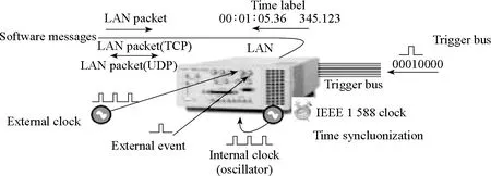
Fig.1 LXI instrument trigger modes
1.1 Events trigger based on LAN packets
LXI instruments receive standardized LAN packets by establishing UDP and TCP connections. Through the analysis of events ID number, such as LAN0, LAN1, …, LAN7, to determine which one is effective. Instruments parse the timestamps in LAN packet to mark the time to execute trigger. LAN trigger is mainly used for events communication between instruments.
1.2 IEEE 1588-based timing triggering
Each LXI instrument has an internal clock; the instrument can be triggered automatically in chronological order. Test system established by the LXI instrument can also run with the time sequence set by testers. Before the instrument is triggered, we need to synchronize the clocks of the aligned time, and the synchronization accuracy can be sub-microsecond. With the development of network technology, the trigger accuracy will be further improved .
1.3 LXI hardware bus trigger
In order to achieve nanosecond synchronization accuracy, LXI instruments provide a hardware bus trigger[9]which is the same as the traditional instrument. This bus has 8 independent channels (LAN0, LAN1, …, LAN7), and the instrument can receive triggering signal from any channel. But this is a compromise for network instrument to improve the triggering accuracy in the LAN. If the network instrument extends to the WAN’s instrument, this mode will be replaced by the network triggering.
2 Synchronization Analysis of LXI Instrument
The synchronization of LXI instrument usually known for IEEE 1588 clock synchronization. Through careful analysis of the data, in fact, LXI instrument synchronization contains three cases as shown in Fig.2.
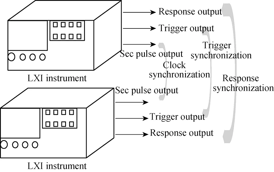
Fig.2 LXI instrument synchronization types
2.1 Clock synchronization
LXI 1.4 protocol[10]requires that each LXI B class and A class instrument must have one sec pulse output port, with pulse output period of 1 s. The output port is mainly used to test whether the two instruments have clock synchronization. However, the signal is periodic, if the gap between the two instruments is greater than one second clock. In this situation, it’s easy to bring in large deviation to determine the synchronization by observing the sec pulse.
2.2 Trigger synchronization
LXI 1.4 protocol requests that if LXI instrument will transfer detected LXI trigger event configuration to another device, the trigger output response time(3.5.2.1 RULE - Specify Trigger Output Response Times) should be given in the instrument manual. For the convenience of testing trigger output response time, equipment manufacturers should provide a trigger output interface. If the instrument receives a trigger command, it will produce a pulse signal (single pulse) to trigger other instruments. Trigger output response time refers to a time interval between the time when instrument receives a trigger output request and that when instrument sends out a trigger signal. Assuming two LXI instrument sets the same timing trigger, by observing delay time of two trigger output pulse to determine synchronization accuracy, this method is called pulse synchronization.
2.3 Response synchronization
LXI 1.4 protocol also requires equipment manufacturers to give the response time under the condition of every possible trigger methods, called trigger response time(3.5.1.3 RULE - Specify Trigger Response Times). Trigger response time refers to a time interval between the time when instrnment receives a trigger signal and that when instrument generates a trigger action(e.g., the signal source outputs a signal, and the oscilloscope starts to acquire the signal). If two LXI signal sources are set with the same trigger time, we can observe the two signals output time to determine the synchronization accuracy, and this synchronization is called response synchronization[11-12].
3 Network Testing System Synchronization Analyses
There are two network testing systems, each including a signal source and an oscilloscope, and all the instruments are connected to the LAN. Two sources emit two phase quadrature waveforms[13]. Waveforms are recorded by two oscilloscopes. In order to keep the two collected signals orthogonal in phase, the two network systems must be synchronized. The following part of this chapter analyse the various factors that affect the system time synchronization[14].


(1)

Similarly,whenthesignalsourceistriggeredafteracertaintriggeroutputresponsetime,emittingatriggerpulsenotifyoscilloscopestartstoacquire,thentheoscilloscopebeginstocollectthesignalafteraknowntriggerresponsetime.Tomeetthecollectsynchronization,timeshouldsatisfy:

(2)


(3)
Inaddition,undernormalcircumstances,thetriggerresponsetimeoftheinstrumentislongerthantriggeroutputresponsetime,viat3>t1.Fort1directlyoutgoingandformingtriggeroutputresponsetime,comparedwitht3,therewillbemoretimeinsignalprocessingandactionexecutingintriggeroutputresponse.
Astheexampleshows,toensurethesynchronizationofnetworktestingsystem,wewouldhaveasettabletriggerdelayfunctioninLXIinstrument,thatisΔt.

Fig.3 Example of network testing system synchronization
4 Trigger Delay Realization in LXI Instrument
Currently, many instruments do not have a delay trigger function, but we often need to pursue high-precision response synchronization(see in the example of section 2). Without changing the basic trigger modes supported by LXI instrument, an additional delay trigger unit seems to be a good choice. Figure 4 shows a schematic diagram of the delay trigger unit.

Fig.4 Schematic of delay trigger unit
Delay trigger unit includes status select and transfer module, clock counting module, and trigger output module. Status select and transfer module is the main part which contains two comparators, four transfer status, and status transfer judgment. Figure 5 is the status transition diagram.
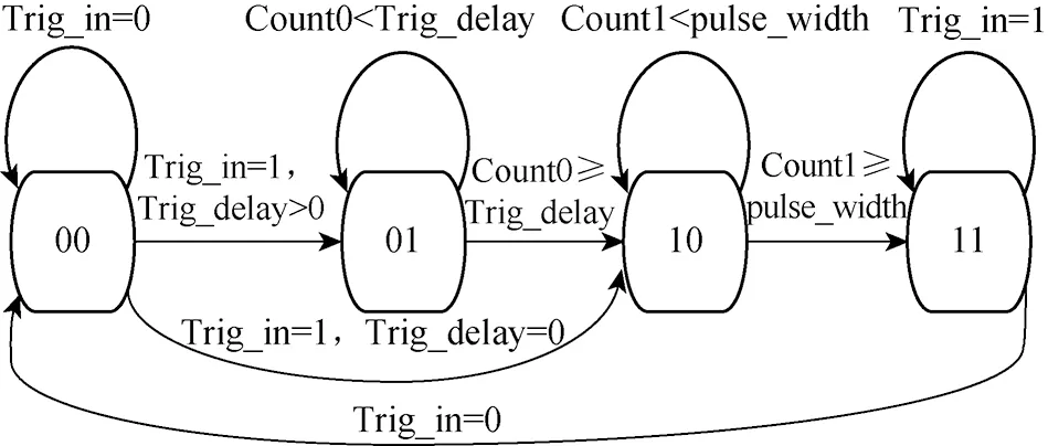
Fig.5 Status transition diagram of status select and transfer module
Delay trigger unit starts from state 00, system firstly detects trigger input signal(Trig_in) and trigger delay time(Trig_delay) to determine the next transition state. If Trig_in=0 which means that there is no delay trigger request, the next state should still be 00; Trig_in=1 which is equals to there is a delay trigger request, check whether Trig_delay =0(trigger delay time is 0), and the next state will immediately shift to 10; otherwise, state should be 01. At state 01, unit determines the next state through comparing value of trigger delay time counter(Count0) with trigger delay time (Trig_delay). If count0 is less than Trig_delay(set by user), the next state must be 01; on the contrary, shifts to state 10. Similarly, at state 10, system should compare trigger pulse width(Pulse_width), also user-set, with trigger pulse time counter value (Count1).When the value of count1 is less than Pulse_width, next state remains in the 10,otherwise entering state 11. State 11 is a specially configured state. In this state, if the last delay trigger response process is not completed, the unit receives a new request (Trig_in=1), and the system will ignore the new one and continue to implement the previous request. Thereby, this way can guarantee every trigger delay is successfully completed.
Clock counting module contains the trigger delay time counter, trigger pulse width time counter, and state judgments. This module is controlled by the states from status select and transfer module. Concretely, states 00 and 01 determine the value of trigger delay time counter. When the current state is 00, value of the trigger delay time counter will set to 0; state 01, the trigger delay time counter starts counting. Likewise, trigger pulse width time counter is controlled by the states 00 and 10. Value of trigger pulse width time counter will be cleared at state 00; state 10, the counter starts counting.
Trigger output module is absolutely controlled by the state 10. At state 10, when the system clock (CLK) is valid and reset signal (nrst) is invalid, the whole unit will always maintain a valid trigger output (Trig_out).
5 Conclusions
In this paper, authors combined a specific example of network testing system synchronization, researched the process from signal transmit to signal acquire, and analyzed the factors affecting the time synchronization. A solution of delay trigger was come up with and a corresponding trigger delay function was implemented. Users may set trigger delay and trigger pulse width time according to the actual case in advance, so as to achieve high-precision network testing system response synchronization.
[1] Luo Y, Wang L.Analyze about Time Synchronization Technique in Auto-test Network System [C].IEEE International Conference on Future Computer and Communication , Wuhan, China, 2010: 831-834.
[2] Yu P , Luo Q H , Liu Z Q. An Automatic Evaluation System for IEEE 1588 Synchronization Clock Unit [C].IEEE International Conference on Electronic Measurement & Instruments, Beijing, China, 2009: 408-413.
[3] Fang J Y, Xiao M Q , Li B.The Realization of the LXI Bus Instruments’ Network Protocols Based on Nios II [C].IEEE Circuits and Systems International Conference, Chengdu, China, 2009: 1-5.
[4] Qiu C Q, Qin H L, Chen Y. Creating Hybrid Test and Measurement System Based on LAN/LXI [C]. IEEE International Conference on Electronic Measurement & Instruments, Beijing, China, 2009: 960-963.
[5] Burch J, Cataldo A, Eidson J,etal. LAN-Based LXI Instrument Systems- the Next Step in the Evolution of Measurement System Technology [C]. IEEE International Instrumentation and Measurement Technology Conference, Victoria, BC, 2008: 399-404.
[6] Li Z, Zhou F L, Yao X J. Research on LXI Trigger Bus [C]. IEEE International Conference on Embedded Software and Systems, Hangzhou, China, 2009: 553-558.
[7] Liu Z Q, Pan S W, Zhang Y G. A Design and Implementation of and Triggering System for LXI Instruments [J].Measurement, 2013, 46(8): 2753-2764.
[8] Loschmidt P, Exel R, Gaderer G. Highly Accurate Timestamping for Ethernet-Based Clock Synchronization [J].JournalofComputerNetworksandCommunications, 2012: 2012-2023.
[9] Loschmidt P, Exel R, Nagy A,etal. Limits of Synchronization Accuracy Using Hardware Support in IEEE 1588 [C]. Precision Clock Synchronization for Measurement, Control and Communication, Ann Arbor, MI, 2008: 12-16.
[10] LXI Consortium. LXI Standard Revision 1.4, May 2011 Edition[S].
[11] Wu S K, Wang J L, Zhao J. FPGA-Based High-Precision Network Time Synchronization Research and Implementation [C]. IEEE International Conference on Electronic Measurement & Instruments, Chengdu, China, 2011: 329-332.
[12] Lin C X, Shao B B, Zhang J. A Multi-channel Digital Programmable Delay Trigger System with High Accuracy and Wide Range [C]. IEEE International Conference on Electronics, Communications and Control, Ningbo, China, 2011: 1835-1838.
[13] Yang Y K, Lei Y J. The Assessment of Navigation Signal Phase Quadrature [C]. IEEE International Congress on Image and Signal Processing, Chongqing, China, 2012: 1726-1729.
[14] Cui B, Dong E Q, Li X Y,etal. A Time Synchronization Algorithm Based on Bimodal Clock Frequency Estimation [C]. Asia-Pacific Conference on Communications, Jeju Island, 2012: 75-78.
[15] Yan X, Wang Q, Qin K Y. A New Signal Capture Method Based on Real-Time Multi-Domain Trigger in Communication Analyzer [C]. IEEE Circuits and Systems International Conference on Testing and Diagnosis, Chengdu, China: 1-4.
[16] Delshad S S, Hamidi Beheshti M. Generalized Projective Synchronization of the Fractional-Order Hyperchaotic Lorenz Systems via a Vector Transmitted Signal [C]. IEEE International Conference on Computing Science and Automatic Control, Tuxtla Gutierrez, Mexico, 2010: 10-15.
Foundation items: Sino-German Joint Research Project of the Sino-German Center for Science (No. GZ817); the Fundamental Research Funds for the Central Universities, China (No. ZYGX2012J090); National Natural Science Foundation of China (No. 61271035)
TP23 Document code: A
1672-5220(2015)01-0132-04
Received date: 2014- 08- 08
*Correspondence should be addressed to MA Min, E-mail: mamin@uestc.edu.cn
猜你喜欢
芳草·文学杂志(2022年1期)2022-02-09
洛阳理工学院学报(社会科学版)(2021年6期)2021-12-15
杂文月刊(2019年20期)2019-12-04
杂文月刊(选刊版)(2019年10期)2019-11-01
科普童话·神秘大侦探(2019年11期)2019-02-06
科普童话·神秘大侦探(2019年11期)2019-02-06
作文评点报·作文素材初中版(2018年43期)2018-11-19
飞魔幻B(2018年1期)2018-03-03
哲思2.0(2017年9期)2017-11-09
鸭绿江(2015年1期)2015-01-20
 Journal of Donghua University(English Edition)2015年1期
- Journal of Donghua University(English Edition)的其它文章
- Joint Optimization Strategy for Video Transmission over Distributed Cognitive Radio Networks
- Asymptotic Behavior of the Drift Coefficient Estimator of Stochastic Differential Equations Driven by Small Noises
- Adaptive Modulation and Coding Based on Fuzzy Logic Cognitive Engine
- Modeling and Simulation of P-Aloha, CSMA/CA and MACAW Protocols for Underwater Acoustic Channel
- Design and Analysis of Axial Thrust Roller-Exciting Vibrating Table and Its Motor-Control System Based on Co-simulation
- Effects of Compression Garments on Lower Limb Muscle Activation via Electromyography Analysis during Running