
Infrared Heating Technology for Automated Fiber Placement
2015-03-21 05:09文立伟孙天峰倪金辉
关键词:腾飞
(文立伟), (孙天峰), (倪金辉),
College of Material Science and Technology,Nanjing University of Aeronautics and Astronautics,Nanjing 210016, P.R.China (Received 10 December 2014; revised 16 February 2015; accepted 20 March 2015)
Infrared Heating Technology for Automated Fiber Placement
WenLiwei(文立伟)*,SunTianfeng(孙天峰),NiJinhui(倪金辉),
ZhuTengfei(朱腾飞)
College of Material Science and Technology,Nanjing University of Aeronautics and Astronautics,Nanjing 210016, P.R.China (Received 10 December 2014; revised 16 February 2015; accepted 20 March 2015)
Prepreg stickiness is the adhesion between prepregs or between a prepreg and a mold in lay-up process. It is critical for automated fiber placement, because the stickiness should be small for smooth transport, as well as large enough on the laying surface for a good placement performance. To ensure prepreg stickiness always being in the optimum laying window, placement temperature should be changed according to the laying speed. In our work, the relationship between laying speed and emissive power of heating lamp was studied. The heat transfer process between heating lamp and laying surface was analyzed and the control equation of dynamic temperature was derived. Finally, the infrared heating system was built and its effectiveness was verified based on placement experiment.
automated fiber placement; infrared heating; stickiness; temperature control
0 Introduction
Automated fiber placement is one of the key technologies of forming composite materials with complex surface and its application has become wide[1-6]. Thanks to its high forming efficiency and reliable forming quality, the technique has been widely used in aeronautics and astronautics. Its advantages depend on advanced forming equipments and precise automated placement process. The high quality and efficient placement of automated fiber placement machine is dominated mainly by those three factors:Prepreg stickiness, placement stress and placement tension.
Prepreg stickiness is primarily controlled by adjusting the temperature of the placement surface. Heating methods for thermosetting prepreg in placement process include hot air heating and infrared heating. Infrared heating is superior at controlled heating direction and heating temperature, fast response, high efficiency and energy saving. Therefore, it is a preferred choice for automated fiber placement heating. Currently, many scholars abroad have focused on infrared heating for automated fiber placement. The Electroimpact Company has studied infrared heating technology on thermosetting composite under high-speed placement. The Ingersoll Machine Tool Company has developed two series of automated fiber placement machines with infrared heating systems, and the radiant intensity of the heating mechanism could be automatically adjusted according to placement speed. Other scholars abroad have studied the effect of temperature on the quality of placement[7-9]. Domestic researches on infrared heating technology basically focuces on their uses in heating, medical, drying and other industries. Hot air heating has been applied in automated tape placement. Yu Yongbo et al.have conducted a preliminary exploration of infrared heating technology for automated tape placement[10-11]. However, the infrared heating for automated fiber placement has not been reported yet. Therefore, we applied infrared heating to automated fiber placement.
1 Stickiness Control for Automated Fiber Placement
The prepreg used in automated fiber placement is a composite made of resin matrix and continuous fiber. The placement speed is high, so the resin ″island″ between two prepreg surfaces does not have enough time to spread. Therefore, the bond between prepregs cannot be guaranteed[12]. In order to solve this problem, prepreg stickiness should be adjusted to increase the flowability of the resin.
The relations between resin stickiness and temperature can be expressed by Arrhenius exponential equation[13]
(1)
whereμxisaconstant,Ethestickinessflowactivationenergy,RthegasconstantandTtheabsolutetemperature.
Eq.(1)illustratesthatadjustingprepregtemperatureonplacementsurfacecansuitablychangethestickinessofprepreg.Infact,whenthetemperatureisrising,themobilityoftheresinmolecularchainisbeingenhanced;theinteractionbetweenmoleculesisweakening,thefluidityofresinisincreasingandtheplacementperformanceofprepregisbeingimproved.Therefore,heatingtheprepregsurfaceisnecessarywhenlayingtheprepreg.ThestructureofheatingsystemisshowninFig.1.

Fig.1 Heating system
Theinfraredheatingsystemshoulddetectlayingspeed,recognizenon-placement,beingheatingadaptive,andrapidlyresponse,etc.TheworkconditionoftheheatingsystemisshowninTable1.

Table 1 Work condition of heating system
Therefore, an infrared heating system was designed for the automated fiber placement machine. This system included a placement speed detection mechanism, a control unit and a heating unit. The placement speed was measured by the encoder which engaged closely with the pressure roller. The status of pressure roller could be monitored by the encoder in real-time. The control unit received the speed signal detected by the encoder, and output the control signal to adjust the heating lamp radiation intensity by monitoring the power of the output module.
2 Infrared Heating Energy Transfer Model
In the placement process, the infrared heating device is at open state. The outside temperature changing and airflow will have an impact on the thermal energy transfer of the infrared radiation. Besides, the temperature and the physical properties, even different types of prepreg can affect the calculation process[14]. Therefore, a simplified radiation calculation was chosen instead of a complicated one for engineering application.
In order to convert filament radiant energy into prepreg heat energy, the radiant energy must reach the effective radiation surface in two ways: One is being directly projected to the placement surface from the filament; the other is being emitted from the filament and reflected by the reflective coating, as shown in Fig.2.
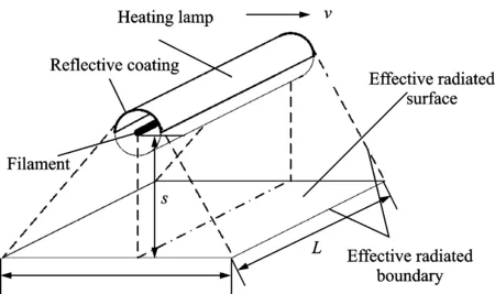
Fig.2 Schematic diagram of radiation
2.1 Infrared heating lamp radiation theory
The filament surface can be regard as diffuse surface. The heat radiation of the filament surface is weaker than the black body surface. According to Stefan-Boltzmann law, the radiation intensity can be expressed as
(2)
whereElistheradiationofthefilament,εtheemissionrateofthefilament,σ0theBoltzmannconstantandTlthetemperatureofthefilament.Thetotalradiationoftheheatinglampisproportionaltofourthpowerofthefilamenttemperature.Thetemperatureofthefilamentdependsonthepoweroftheheatinglamp.Whentheheatinglampisinthermalequilibriumwiththeenvironment,theradiationofthefilamentcanbeexpressedas[15]
(3)
wherePis the power of the heating lamp, andSthe effective radiation area of the filament.Eq.(3) shows that the radiation intensity of the heating lamp can be changed by adjusting the power of the heating lamp.
2.2 Computation of radiant energy for heating lamp
The radiant energy emitted from the filament and directly projected to the effective radiation surface in unit time can be expressed as
(4)
whereφ1,3istheangularcoefficientbetweensurface1andsurface2,thatistheefficiencyoftheradiantenergyemittedfromthefilament1andfallingontheprepregsurface3.
Theradiantenergywhichisreflectedbythereflectivecoatingandfinallyreachestheprepregsurfaceinaunittimecanbeexpressedas
(5)
whereφ1,2istheangularcoefficientbetweensurface1andsurface2,thatistheefficiencyoftheradiantenergyemittedfromthefilament1andfallingonthereflectivecoatingsurface2,φ2,3theangularcoefficientbetweensurface2andsurface3,thatistheefficiencyoftheradiantenergyreflectedbythereflectivecoatingsurface2andfallingontheprepregsurface3,ξthereflectanceofthereflectivecoating.
2.3 Computation of radiant energy prepreg-absorbed
The radiant energy that is projected to the effective surface from the heating lamp is the sum of the direct radiation and indirect radiation. Considering the usual range of thermal radiation used in the placement, the prepreg surface can be regarded as gray body, so the prepreg absorption ratio is constant. The radiant energy that the prepreg absorbed in a unit time can be expressed as
(6)
whereδistheprepregabsorptionratio.
2.4 Dynamic temperature control equation
Automated fiber placement is a dynamic process. The heating device sweep the placement surface in placement rate. The heated surface of the prepreg receive the radiant energy from the heating lamp. The vibration of the resin molecules increases and the temperature of the prepreg rises. The relationship between the temperature change of the prepreg surface and the received radiant energy can be expressed as
(7)
whereCisthespecificheatcapacityofprepreg,mtheprepregmassintheeffectiveradiationsurface, ΔTthetemperaturevaluesinplacementsurface,Lthelengthalongthetrackdirectionontheeffectiveradiationsurfaceandvthe placement rate along the track direction.
In order to maintain the prepreg on the placement at a optimal temperature, the relationship between the power of the heating lamp and the placement rate can be expressed as
(8)
Due to the introduction of the hypothesis of diffuse surface, the angular coefficient is geometrical. It only relates to the size and the shape of the filament surface and the prepreg surface, and the relative position between the filament and the prepreg, instead of the properties and temperature of the prepreg. This property of angular coefficient is also suitable for the system which is not in thermal equilibrium. During automated fiber placement, the laying fiber head is usually perpendicular to the common tangent of the placement surface. The relative position of the heating lamp which is on the laying fiber head and the placement surface is unchanged, and the effective heating surface remains unchanged, and the angular coefficientφ1,2,φ2,3,φ1,3areconstants.Sothecontrolequationoftheheatinglampcanbeexpressedas
P=kvΔT
(9)

Thereby, the relationship between the placement rate and the power of the heating system has been established, and the control coefficientkcan be established by placement test.
3 Infrared Heating System
The infrared heating device is located at the black of the pressure roller. Two infrared heating lamps were adopted, each of which was with gold reflective coating and with an effective heating length of 80 mm. The power of each lamp was 1 kW. The infrared heating device was shown in Fig.3.
The control program, based on the dynamic temperature control equation, was loaded in the control unit. The control unit output appropriate analog and adjusted the power of the output model to mornitor the temperature of the placement surface in real time. The control principle is shown in Fig.4.
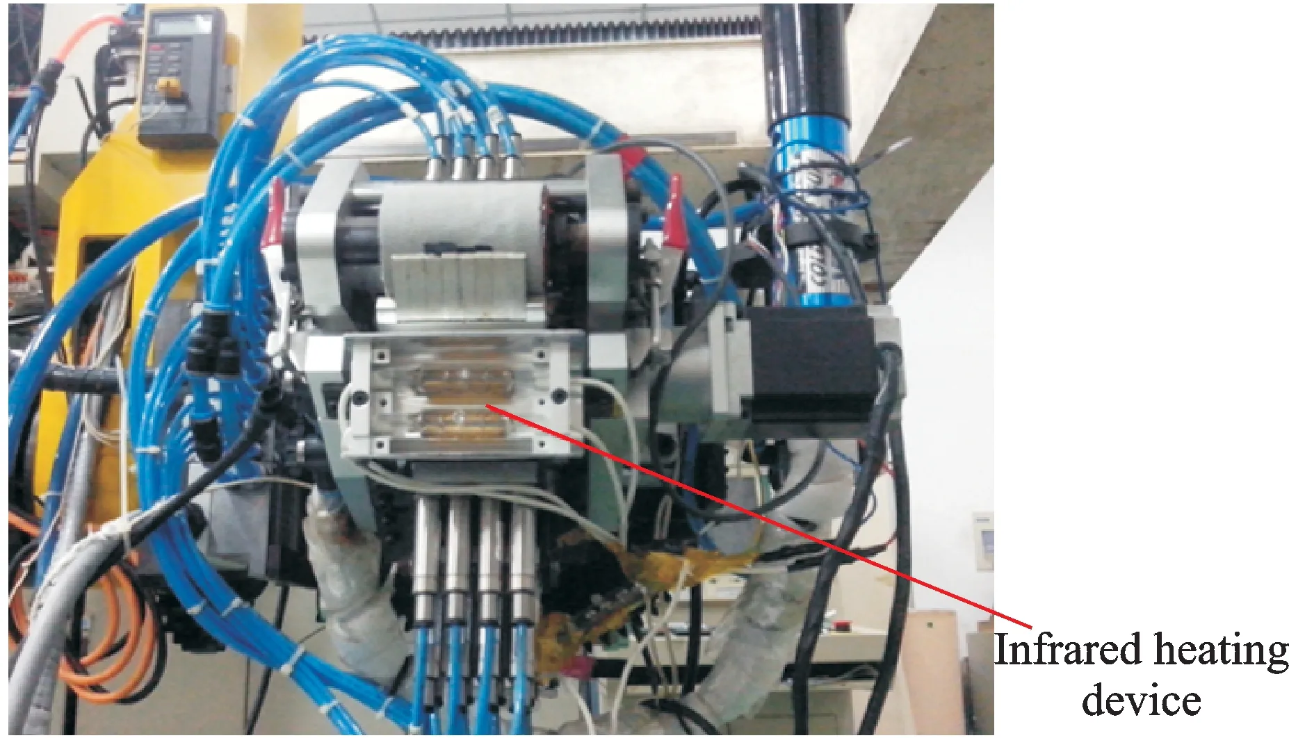
Fig.3 Infrared heating device

Fig.4 Control process
3.1 Power adjustment mechanism
Heating system adjusted the heating lamp power by a voltage regulator module, therefore a relationship should be established between the heating lamp operating voltage and the heating lamp power. After heating lamp started to work, the filament temperature was greatly increased. The greater the heating lamp power was, the higher the filament temperature was and the stronger the radiation was. On the contrary, the less power heating lamp held, the lower the filament temperature was and the weaker the radiation became. It was exactly because the filament temperature affected by the filament resistivity and the filament resistance was not fixed, since the heating lamp power voltage was not applied to the simple linear change. Testing with an infrared lamp quartz halogen lamp, lamp temperature increased with tungsten resistivity increasing.According to the characteristics of the resistance of the filament, the filament resistance can be expressed as
(10)
whereρisthefilamentresistivity.Resistivityisthephysicalcharacteristicsofthefilament,mainlywiththefilamenttemperatureTvaries linearly,the relationship betweenρandTcan be expressed as
(11)
whereα,βaretheconstantsforthesameinfraredheatinglamp.
Heatinglamppowerversusvoltagecanbeobtainedbyexperimentalmeasurements.Aeight-tow-fiberplacementmachineheatinglamppowerandvoltagecurveisshowninFig.5.
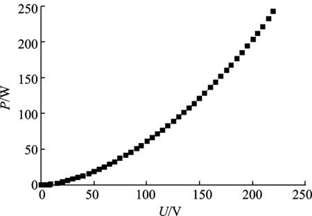
Fig.5 Heating lamp power and voltage relationship
Relationsbetweenpowerandvoltagecanbeobtainedas
P=0.004 12U2+0.192 82U-0.923 39
(12)
whereUis heating lamp operating voltage.
According to the target power, the control unit calculated the heating lamp operating voltage by Eq.(12). And then direct ratio relationship calculated the control voltage and outputs based on the ratio of input control voltage and output voltage of voltage regulator module.
4 Experimental Verification and Analysis
The experiments were conducted with the T700/603 epoxy unidirectional prepreg where parameters are listed in Table 2.

Table 2 Parameters of the prepreg
4.1 Control coefficient
The control coefficients are different with different prepregs and different ambient temperatures, so they need to be amended before laying prepreg. In order to determine the control coefficient, the placement speed was set at 6 m/min, the value of the control coefficient was adjusted to adapt all kinds of placement experiments. Then the temperature of the placement surface was measured by infrared thermometer. The experiment data are listed in Table 3.

Table 3 Relationship between control coefficient and temperature
From Table 3, we can get the curve and the fitting equation between the control coefficient and the temperature of the placement surface, as shown in Fig.6.

Fig.6 Relations between control coefficient and temperature
The placement surface temperature of epoxy composite prepreg should be at 35 ℃[16]. According to the fitting equation, the control coefficient should be 4.39. Therefore, The control coefficient was set at 4.39 and the placement experiment was conducted at different placement speeds. The placement surface temperature could be measured. Other parameters are shown in Table 4. The experiment results are shown in Table 5.

Table 4 Placement parameters

Table 5 Surface temperature at different placement speeds
Tables 4,5 show that the power of the heating lamp matched the placement speed. The temperature of the placement surface was maintained at less than 32—35 ℃. Therefore, the theory temperature modelp=kvΔT,namelythelinearcontrolmodelbetweenthepowerandtheplacementspeed,isreasonable.
4.2 Heating effect on inter-layer property
The peel force was adopted to evaluate the inter-layer adhesion properties of epoxy prepreg. Put the specimen on the peeling tester machine, one end of the up layer prepreg was fixed in the chuck of the machine. Move up the chuck at the speed of 100 mm/min until the peeling length between the upper and lower prepreg was 60 mm. Record the ″force-displacement curve″, and then calculate the average peeling force. Experimental device is shown in Fig.7.

Fig.7 Peeling experiment device
The stickiness value between the prepreg layers can be expressed as
(13)
whereSpaccisthestickinessvaluebetweentheprepreglayers,justrepresentingtheinterlayeradhesivepropertiesoftheprepreg,withaunitofN/mm,Pcptheaveragepeelingforce,Bthe width of the prepreg.
With a placement speed of 6 m/min, the control parameters changed with different placement tests. Other placement parameters are listed in Table 4 to determine the peeling force. The experimental data are listed in Table 6.
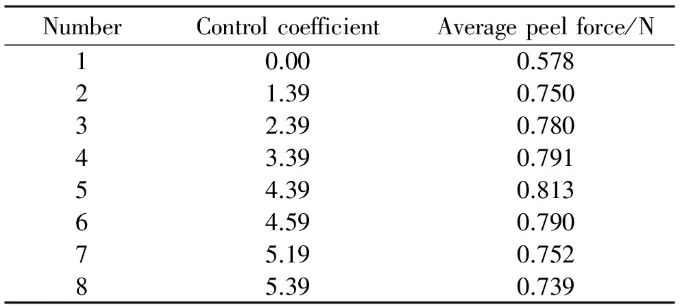
Table 6 Control coefficient effect on peel force
The value of the peeling force can characterize the sticking performance of prepreg layers. The better the sticking performance of prepreg layers was, the less the warp and poor inter-layer combination would appear. We could see from Table 6 that the peeling force had been significantly improved after heated and the peeling force increased with the control coefficient increasing. Whenk=0,theheatinglampdidnotwork,thenthepeelingforcewassignificantlylowerduringheating.Whenk=4.39,thepeelingforcereachedthemaximum,butwhenthecontrolcoefficientcontinuedtoincrease,thepeelingforcewasdecreasing.
4.3 Heating effect on curing degree of prepreg
Due to the large power of the heating lamp, excessive radiant energy may damage the prepreg, especially at the positions where the laying fiber head has sharply stopped, such as cut prepreg point and feed prepreg point, as shown in Fig.8. In these suspension points, placement speed is zero, the heating lamp is out of power. But the lamp and the filament is still hot and will continue to heat the placement surface until they are totally cooled down by convection heat transferring and radiation transferring. It is necessary to take full account of the heating impact on the prepreg performance at the special positions. Therefore, we measured and analyzed the curing degree of the laid prepreg.

Fig.8 Segment of placement track
In order to characterize the curing degree, the differential scanning calorimetry was adopted to measure the thermal effect during raising temperature in equal rate of the prepreg at different points with different characteristics. There were three kinds of attributes of laid prepreg: Not heated, heated at regular point and heated at short stop point with control coefficientk=4.39. These enthalpies of these three specimens at the heating rate of 5 K/min were tested, and the curing degree was calculated. The experiment results are listed in Table 7.

Table 7 Enthalpy and curing degree of different segments
Table 7 elaborates that the curing degree of the not heated prepreg was 10.24% and the curing degree of the prepreg which was laid with heated at uniform velocity and at the short stop point was slightly increased. The curing degree of prepreg which was laid with heated at uniform velocity was increased 4.85% more than the prepreg which was not heated, the curing degree of prepreg which was heated at the short stop point has increased of 12.6%. Although the initial curing degree of the laid prepreg has changed, the effect of the curing degree change was relativelly very small, so heating did not damage the prepreg, and the placement quality has greatly improved after heated. The change of the curing degree at the shot stop point was greater, because when the heating lamp was out of power, the lamp and the filament were still hot and could not immediately cool down to room temperature. The longer the laying fiber head stops at the short stop position, the more calories the prepreg accept, and the higher the curing degree of the prepreg is.
4.4 Heating effect on placement quality
The placement experiments were conducted withk= 4.39 at different placement rates. without heat,kwas 0. Other placement parameters were listed in Table 4. Fig.9 is the placement effect under different placement conditions. Without heat, warp was enormous and inter-layer combination was poor. The surface was almost uneven at low ambient temperature. After heated, the temperature of the placement surface increased, the placement quality had a very significant improvement, the placement surface was smooth and the prepreg layers sticked closely. The placement quality was consistent under placement rate of 100, 150, and 200 mm/s. The experiment verified the feasibility of the dynamic temperature control equation and the heating device.

Fig.9 Placement results with different parameters
5 Conclusions
(1) Placement performance of the prepreg at the placement surface can be adjusted by infrared heating during automated fiber placement.
(2) According to dynamic temperature control model, a heating control system was built. The experiment results showed that the proposed control system could match the power of the heating lamp with the placement speed, which verified the feasibility of the system.
(3) The placement quality and the curing degree of the laid prepreg showed that the heating system could improve the placement quality effectively without damaging the prepreg on the placement surface. The heating system is fully applicable to automated fiber placement machine.
Acknowledgements
This work was supported by the Key Basic Research and Development Program(973)(No. 2014CB046501) and the Priority Academic Program Development of Jiangsu Higher Education Institutions.
[1] Li Yong, Xiao Jun. The technology and application of fiber placement[J]. Fiber Composites, 2002, 19(3): 39-41.(in Chinese)
[2] Mair R I. Advanced composite structures research in Australia[J]. Composite Structures, 2002, 57(1): 3-10.
[3] Harris C E, Starnes J H, Shuart M J. Design and manufacturing of aerospace composite structures, state-of-the-art assessment[J]. Journal of aircraft, 2002, 39(4): 545-560.
[4] Hollaway L C. The evolution of and the way forward for advanced polymer composites in the civil infrastructure[J]. Construction and Building Materials, 2003, 17(6): 365-378.
[5] Yan Biao, Xiao Jun, Wen Liwei , et al. Prepreg tows auto-splicing method and system[J]. Journal of Nanjing University of Aeronautics and Astronautics, 2013, 45(2): 250-254.(in Chinese)
[6] Wen Liwei, Xiao Jun, Wang Xianfeng, et al. Progress of automated placement technology for composites in China[J]. Journal of Nanjing University of Aeronautics and Astronautics, 2015, 47(5): 637-649.(in Chinese)
[7] Sonmez F O, Akbulut M. Process optimization of tape placement for thermoplastic composites[J]. Composites Part A: Applied Science and Manufacturing, 2007, 38(9): 2013-2023.
[8] Heider D, Piovoso M J, Gillespie Jr J W. A neural network model-based open-loop optimization for the automated thermoplastic composite tow-placement system[J]. Composites Part A: Applied Science and Manufacturing, 2003, 34(8): 791-799.
[9] Shirinzadeh B, Alici G, Foong C W, et al. Fabrication process of open surfaces by robotic fibre placement[J]. Robotics and Computer-Integrated Manufacturing, 2004, 20(1): 17-28.
[10]Yu Yongbo, Wen Liwei, Xiao Jun, et al. Study of infrared heating technology in automatic tape-laying[J]. Acta Aeronautica et Astronautica Sinica, 2011, 32(6): 1124-1131.(in Chinese)
[11]Wen Liwei, Yu Yongbo, Qi Junwei, et al. Study on infrared heating system base on automatic tape laying[J]. Acta Aeronautica et Astronautica Sinica, 2011,32(10): 1937-1944.(in Chinese)
[12]Gutowski T G, Bonhomme L. The mechanics of prepreg conformance[J]. Journal of Composite Materials, 1988, 22(3): 204-223.
[13]Li Yong, Zhu Fei, Xiao Jun, et al. The affection of additions component on viscosity of up resin[J]. Hi-tech Fiber & Application, 2002, 27(3): 28-30.(in Chinese)
[14]Guo Kaibo, Chen Liping, Shi Yushen, et al. Study on performance characteristics of sodium silicate sand hardened by superfines[J]. China Mechanical Engineering, 2009 (8):996-999.(in Chinese)
[15]Liu Shouwen, Pei Yifei, Sun Laiyan. Research on spectral pattern of infrared lamp for thermal vacuum test of spacecraft[J]. Journal of Astronautics, 2001,31(1): 254-258.(in Chinese)
[16]Zhou Yanyun, Huang Yudong, Liu Zaiyang, et al. Research on placement techniques of epoxy matrix composite prepreg[J]. Chemistry and Adhesion, 2009,31(3): 72-74.(in Chinese)
(Executive Editor: Zhang Bei)
TB332 Document code: A Article ID: 1005-1120(2015)06-0631-08
*Corresponding author: Wen Liwei, Associate Professor, E-mail: wenliwei@nuaa.edu.cn.
How to cite this article: Wen Liwei, Sun Tianfeng, Ni Jinhui,et al.Infrared heating technology for automated fiber placement[J].Trans. Nanjing u.Aero.Astro., 2015, 32(6):631-638. http://dx.doi.org/10.16356/j.1005-1120.2015.06.631
猜你喜欢
小哥白尼(趣味科学)(2021年10期)2022-01-17
江苏教育·书法教育(2021年3期)2021-01-17
快乐语文(2018年25期)2018-10-24
人大建设(2017年11期)2017-04-20
中国环保产业(2017年2期)2017-03-03
中学生数理化·七年级数学人教版(2016年8期)2016-12-07
金色年华(2016年19期)2016-02-28
现代企业(2015年6期)2015-02-28
中国火炬(2010年6期)2010-07-25
 Transactions of Nanjing University of Aeronautics and Astronautics2015年6期
- Transactions of Nanjing University of Aeronautics and Astronautics的其它文章
- Unicast Network Topology Inference Algorithm Based on Hierarchical Clustering
- Structure Design of Shaped Charge for Requirements of Concrete Crater Diameter
- Fault Detection Based on Incremental Locally Linear Embedding for Satellite TX-I
- Deformation Analysis on Shear-Bending of Ring-Shaped Piezoelectric Actuator
- Mechanical Behavior of Bistable Bump Surface for Morphing Inlet
- Effect of Tip-Blade Cutting on the Performance of Large Scale Axial Fan