
Modeling and Identification Approach for Tripod Machine Tools
2015-03-21 05:09石勇刘文涛
(石勇), (刘文涛)
1. College of Power and Energy Engineering, Harbin Engineering University, Harbin 150001, P.R.China;2. School of Mechatronic Engineering, Harbin Institute of Technology, Harbin 150001, P.R.China (Received 4 November 2014; revised 24 December 2014; accepted 25 March 2015)
Modeling and Identification Approach for Tripod Machine Tools
ShiYong(石勇)1*,LiuWentao(刘文涛)2
1. College of Power and Energy Engineering, Harbin Engineering University, Harbin 150001, P.R.China;2. School of Mechatronic Engineering, Harbin Institute of Technology, Harbin 150001, P.R.China (Received 4 November 2014; revised 24 December 2014; accepted 25 March 2015)
To improve stiffness and workspace of tripod machine tools, a device called tripod machine tool was proposed with five degrees of freedom. First, the structure and pose description of the tripod machine tool were introduced, and then its backward and forward kinematics models were analyzed. To identify parameters of the tripod machine tool, a parameter identification method based on an error-sensitive analysis was presented.Then geometrical structural identification model was deduced by establishing the pose relative error model at two different points of the tripod machine tool. The method employed a sensitivity matrix by using a difference operator to explain pose changes of the tripod machine tool with respect to its main geometrical structural parameters. Finally, the position error of a tripod machine tool was reduced from 1.74 mm to 0.44 mm. Therefore, the proposed identification method was verified to be effective and feasible.
tripod; error sensitivity analysis; calibration; identification
0 Introduction
To improve stiffness and workspace of Tripod machine tools, a series-parallel hybrid machine tool called tripod was proposed, as shown in Fig. 1. The parallel part of the tool was comprised a base platform, a moving platform, and three legs with adjustable lengths. One end of each leg was connected to the moving platform by a revolute pair, and the other end of two was connected to the base platform by Hooke joints; the third leg was connected to the base platform by a ball joint or Hooke joint with three degrees of freedom (DOFs). The parallel part of the tripod machine tool has three DOFs. The motion parameters of the parallel part have coupling characteristics. The position parameters of the tripod machine tool are independent from each other, but the orientation parameters are calculated with those position parameters. To increase the flexibility of the tripod machine tool, two perpendicular rotary shafts were installed under the moving platform in series, which has two DOFs.

Fig.1 Tripod machine tool
Accuracy of the tripod machine tool is inevitably affected by manufacturing and installation errors inevitably. Therefore, tripod machine tools must be calibrated before application. In general, calibration methods can be classified into three types: External calibration, constrained calibration, and auto-calibration or self-calibration[1]. Self-calibration requires internal sensors. Usually, the number of internal sensors is larger than that of DOFs of calibrated mechanisms[2-3]. Constrained calibration is implemented by constraining some of DOFs of the calibrated mechanisms and keeping some geometric parameters constant throughout the whole process. Constrained calibration does not require extra sensors[4]. External calibrations neither require additional internal sensors nor restrict some of the DOFs of calibrated mechanisms. The position and orientation information of calibrated mechanisms are obtained using external measuring devices, such as a laser tracker, an inclinometer, or a coordinate measuring maching (CMM). This calibration method has been widely used[4-8].
Recent literature have reported identification model of parallel machine tools (PKM). Based on PKM forward kinematics model, Ref.[9] constructed an influence coefficient matrix with the pose errors and structure errors of PKM by a numerical method using measured data. A min-max optimization method was presented in Ref.[10] based on the least square optimization method to eliminate a few large residual errors that lie in the parameter identification. An experiment proved that the min-max optimization method directly correlated the precision evaluation with the kinematics calibration and improved the total accuracy of PKM tools simply and inexpensively. In Ref.[11], indirect measurements of the position and orientation of moving platform were performed using a photoelectric length gauge with balls. Since measuring noises caused final calculation results seriously to deviate from the real existing error values of the machine tool, Jacobian matrix regrouping method was presented to minimize magnification of measuring noises while identifying parameters. A so-called cocktail method was an example of it[12]. The structure error Jacobean matrix was automatically constructed based on the forward kinematics model, and generalized coordinates consistent with the measuring apparatus were adopted. The method can employ different types of common measuring apparatus or the combination of them when a Stewart platform is calibrated, thus so the special equipment for multi-freedom measurement is unnecessary. In Ref.[13], an error compensation method was designed to compensate for manufacturing and assembly error by developing a 3-point-3-axe measurement method so that position accuracy, and other attributes were improved.
Our work was to propose a structural characteristic and kinematic model for tripod machine tools. A parameter identification method was designed based on parameter error sensitivity matrix proposed. The method measured relative position and orientation error of tripod machine tools in different moving directions and different spaces. Then,we constructed a parameters error sensitivity matrix by using a numerical method.Combining the matrix and the relative pose error data, the geometrical structure parameters of tripod machine tools were identified. Our results showed that the method was convenient, practical and efficient.
1 Main Parameters of Tripod Machine Tool
The main geometrical parameters of the tripod machine tool are shown in Table 1. The parameters include position parameters of joints on the base platform, installing error of the joints on the base platform in the vertical direction, position coordinates of the joints on the moving platform, geometrical structure parameters of series part, etc. There are a total of 12 parameters. Fig. 2 shows a schematic of those parameters.

Table 1 Parameters of the tripod machine

Fig.2 Schematic of tripod platform parameters
3 Description of the Orientation of Moving Platform


As shown in Fig. 1, define pointMas the intersection of lineB2R4andB1B3, and draw linesA1M,A3M,A1B2,A3B2, andOM. It is obvious thatA1A3B3B1forms a plane four bar mechanism. Since lineR4Mis perpendicular to planeA1A3B3B1, both △MA1B1and △MA3B2are right-angled triangles. Thus, the following equations can be obtained
(1)
(2)
According to definitions in Table 1, we haveR4B2=d1andR4M=d2. Substitute them into Eqs. (1,2) and then add the two results in the following equation
(3)
Due to the structural constraint,θy∈(-90°,90°). Hence, cosθy≠0. From Eq. (3), the following equation can be obtained
(4)
By adding Eq. (1) and Eq. (2),θycan be obtained as
(5)
In Fig. 1, becauseB1B3∥A1A3andA1A3⊥OA2, thusB1B2⊥OA2. SinceB1B3⊥MOA2B2andB1B3⊥A2B2, the following equation can be obtained
(6)
Substitute the geometrical structure, position, and orientation parameters into Eq. (6),θxcanbeexpressedas
(7)
Therefore,thethreeconstraintequationsintheparallelpartareEqs. (3,5,7).
Intheseriespartoftripodmachinetools,thedescriptionofmotionscanbeexpressedbyanglesθ4andθ5of the two rotary shaftsS4andS5.
3 Kinematics Model
3.1Backward kinematics model the tripod machine tool
The backward kinematics model of tripod machine tools is used to calculate lengthsli(i=1,2,3) of the three legs and anglesθ4andθ5of the two rotary shafts, on the condition that the tool
3.1.1Backward kinematics model of parallel part
(1) Calculating the position coordinates of the moving platform


(8)

Namely
(9)
wheresdenotes the trigonometric function cos, andζthe trigonometric function sin.

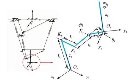
Fig.3 Schematic of serial structure for analysis
(2) Calculating the lengths of three the legs

After coordinate transformation, the position coordinates of joint are expressed as
Thus, the lengths of the three legs are
(10)
3.1.2Backward kinematics model of the series part

(11)

(12)
Since Eq. (11) is equal to Eq. (12), by using Eqs. (5, 7, 9), trigonometric equations forθ5can be created. An explicit solution to the equations is difficult to obtain, but the equations can be solved using a numerical iteration algorithm.

(13)
3.2Forward kinematics model of the tripod machine tool
The forward kinematics model of the tripod machine tool is used to calculate the position of the tool center point and orientation of the tool, on the condition of the lengthsli(i=1,2,3) of three legs and the angles of two rotary shafts are known.
3.2.1Forward kinematics model of the parallel part
Using knowledge of the lengths of 3-legs to calculate the position and orientation of the moving platform is called the forward kinematics model of the moving platform.
From Eqs. (3, 5, 7), one obtains thatθx,θy,θzare functions ofxO1,yO1, andzO1, respectively. Therefore, the transformation matrixTis also a matrix ofxO1,yO1,andzO1. With Eq. (10), equations for three unknownxO1,yO1,zO1can be created. The results of the equations are difficult to calculate, but a numerical iteration algorithm can be used to solve them.
After the positionsxO1,yO1,zO1of the moving platform are solved, the orientationθx,θy,θzof the moving platform can be determined using Eqs. (3, 5, 7).
3.2.2Forward kinematics model of the series part
The forward kinematics model of the series part involves calculation of the position and orientation of the tool on the condition of knowing the position and orientation coordinates of the moving platform and anglesθ4andθ5of the two rotary shafts.

O2=O1+
(14)

(15)
TheEulerangleorientationofthetoolcanbewrittenas
(16)
(17)
Angleγisnotimportanttothemachining.Commonly, γ=-α.
4 Identification Approach of Tripod Machine Tools
4.1Parameter error analysis and parameter identification

(18)

(19)
(20)
Using Taylor′s expansion and removing the high order terms, the following equations are obtained
Hence
(21)
Namely
(22)
Eq. (22)canbeexpandedasfollows

(23)
After transformation, Eq. (8) can be written as
(24)
From Eq. (24), we know that each item of matrixJis the effect of a geometrical parameter error on the output of the tripod machine tool, namely, the sensitivity of parameter error with respect to the output error. Therefore, if we can obtain the error sensitivity matrixJand measure the error data, we can identify the geometrical structure parameter errors of tripod machine tools.
4.2Error sensitive matrix calculation and identification of the tripod machine tool
Since the closed form solution of the forward kinematics model cannot be obtained, it is very difficult to directly construct the error sensitivity matrixJusing partial differential. In practice, we can displace each partial differential inJusing the forward difference operator as follows
(25)
We certainly also can use the center difference, backward difference, or small step difference instead of the forward difference.


Table 2 Results of central difference with a ±1 mm step
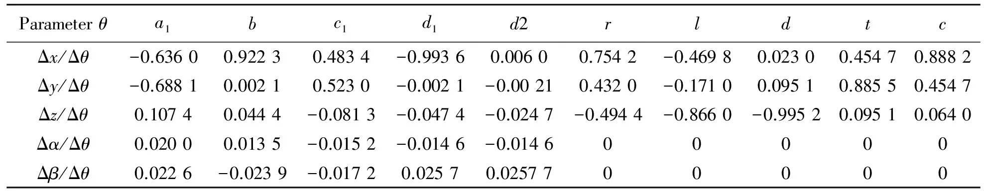
Table 3 Results of the forward difference with a 1 mm step

Table 4 Results of the central difference with a ±0.1 mm step
In a measurement, the data in Δeare probably not sufficient to identify 12 structural parameters. To obtain better results, it is necessary to measure more data in different directions and different spatial locations. We can establish a series of error sensitivity matricesJ1,J2,…,Jnand its corresponding measurement errors Δe1,Δe2,…,Δen. As a result, we can establish the equations
To solve the above equations, we establish a target function: minF=‖Δe-JΔθ‖, and adopt an optimization method to solve it. Finally, the geometrical parameter errors of tripod machine tools can be obtained with the identification method.
5 Application
To validate the identification method, an experiment was performed on LINKS-EXE700 tripod machine tools, shown in Fig. 4. The machine tool was made by Harbin Measuring & Cutting Tool Group Co. Ltd. in China. The nominal geometrical structure parameters of the machine tool are shown in Table 5.

Table 5 Initial parameter values and correction results of the tripod platform mm

Fig.4 LINKS-EXE700 tripod machine tool
Before calibration, the error data of the tripod machine tool must be measured. In the measurement process, the following matters must be addressed:
(1) To avoid only obtaining good accuracy in the local workspace of the machine tools, measurement data should cover the whole workspace of tripod machine tools.
(2) If some accuracy of the geometrical structural parameters can be guaranteed in the process of manufacturing and installation, other parameters can be identified. As a result, the corresponding measurement data and error sensitivity matrix can be reduced.
(3) As known from the identification model, if a high identification precision of tripod machine tools is to be demanded, the initial errors of the mechanism should not be too large. Otherwise, the identification requires multiple calibrations.


Fig.5 Measure error data

Table 6 Results of measurement error and residual error mm
Fig. 6 shows the plot of the calibration results. The measurement error range of the tripod machine tool is [-0.956, 0.792], and the residual error range is [-0.236, 0.219]. The absolute error of the tripod machine tool is reduced from 1.74 mm to 0.44 mm.

Fig.6 Results of measurement error and residual error
6 Conclusions
Structure and pose description method of tripod machine tools was introduced, and the kinematics model was analyzed. An identification method for the tripod machine tool was presented and implemented. The proposed method was validated by an experiment. The following conclusions can be drawn.
(1) The parameter error sensitivity matrix represents the structure parameter errors with respect to the output error of tripod machine tools. Taking advantage of the matrix, the parameters of tripod machine tool can be identified.
(2) Since the partial differential of the kinematics model cannot be directly obtained, the error sensitivity matrix of the tripod machine tool can be created using a numerical method. To accurately identify the parameters of the tripod machine tool, a group of error sensitivity matrices and measurement data are built, and the parameters can be calculated using an optimization method.
(3) The method can also be used for identifying parameters of other non-linear systems using an explicit mathematical model.
[1]Majarena A C, Santolaria J, Samper D, et al. An overview of kinematic and calibration models using internal/external sensors or constraints to improve the behavior of spatial parallel mechanisms[J]. Sensors, 2010, 11 (10): 10256-10297.
[2]Hesselbach J, Bier C, Pietsch I, et al. Passive-joint sensors for parallel robots[J]. Mechatronics, 2005, 15(1):43-65.
[3]Gao Jianshe, Cheng Li, Zhao Yongsheng. Kinetic self-calibration of novel 5-DOF parallel machine tool[J]. Computer Integrated Manufacturing Systems, 2007, 13 (4):738-743.(in Chinese)
[4]Ren X D, Feng Z R, Su C P. A new calibration method for parallel kinematics machine tools using orientation constraint[J]. Int J Mach Tools Manuf, 2009, 49(9):708-729.
[5]Chiang M H, Lin H T, Hou C L, Development of a stereo vision measurement system for a 3D three-axial pneumatic parallel mechanism robot arm[J].Sensors, 2011, 11(2):2257-2281.
[6]Daney D. Kinematic calibration of the Gough platform[J]. Robotica, 2003, 21(6):677-690.
[7]Trapet E, Savio E, de Chiffre L. New advances in traceability of CMMs for almost the entire range of industrial dimensional metrology needs CIRP[J]. Ann Manuf Technol, 2004, 53(1):4330- 4338.
[8]Majarena A C, Santolaria J, Samper D, et al Modelling and calibration of parallel mechanisms using linear optical sensorsand a coordinate measuring machine[J]. Meas Sci Technol, 2011, 22(10):1-12.
[9]Zhong Shisheng, Yang Xiaojun, Wang Zhixing. Research on calibration method based on 6-TPS type parallel machine tool[J]. Computer Integrated Manufacturing Systems, 2005, 11(10):1069-1074.
[10]Gao Meng, Li Tiemin, Ye Peiqing, et al. Precision evaluation oriented parameter identification of PKM tools[J]. Chinese Journal of Mechanical Engineering, 2005, 41(5):79-84.(in Chinese)
[11]Wei Shimin, Zhou Xiaoguang, Liao Qizheng. Research on the kinematics calibration of six-axes parallel maehine tool[J]. China Mechanical Engineering, 2003, 14(23):1981-1986. (in Chinese)
[12]Liu Wentao, Tang Dewei, Wang Zhixing. Cocktail method for Stewart platform calibration[J]. Chinese Journal of Mechanical Engineering, 2004, 40(12):48-53. (in Chinese)
[13]Yung Ting, Jar H C, Li C C. Measurement and calibration for Stewart micro-manipulation system[J]. Precision Engineering, 2007, 31(3):226-233.
(Executive Editor: Zhang Bei)
TG659Document code:AArticle ID:1005-1120(2015)06-0665-09
*Corresponding author: Shi Yong, Associate Professor, E-mail: sy_hit@163.com.
How to cite this article: Shi Yong, Liu Wentao. Modeling and identification approach for tripod machine tools [J]. Trans. Nanjing U. Aero. Astro., 2015,32(6):665-673. http://dx.doi.org/10.16356/j.1005-1120.2015.06.665
 Transactions of Nanjing University of Aeronautics and Astronautics2015年6期
- Transactions of Nanjing University of Aeronautics and Astronautics的其它文章
- Unicast Network Topology Inference Algorithm Based on Hierarchical Clustering
- Structure Design of Shaped Charge for Requirements of Concrete Crater Diameter
- Fault Detection Based on Incremental Locally Linear Embedding for Satellite TX-I
- Deformation Analysis on Shear-Bending of Ring-Shaped Piezoelectric Actuator
- Mechanical Behavior of Bistable Bump Surface for Morphing Inlet
- Effect of Tip-Blade Cutting on the Performance of Large Scale Axial Fan