
New auto color correction algorithm for microscopic imaging system①
2015-04-17 06:27JiangGangyi蒋刚毅
High Technology Letters 2015年3期
关键词:刚毅
Jiang Gangyi (蒋刚毅)
(*School of Information Science and Engineering, Ningbo University, Ningbo 315211, P.R.China)(**National Key Lab of Software New Technology, Nanjing University, Nanjing 210023, P.R.China)
New auto color correction algorithm for microscopic imaging system①
Jiang Gangyi (蒋刚毅)②
(*School of Information Science and Engineering, Ningbo University, Ningbo 315211, P.R.China)(**National Key Lab of Software New Technology, Nanjing University, Nanjing 210023, P.R.China)
Color difference may exist between two views of stereoscopic images acquired with stereomicroscope, which makes trouble for the following image processing or observation. A color correction method based on the nearest cumulative histogram matching is proposed. Histogram-based contrast (HC) method is proposed to define saliency value of each pixel, then auto Grabcut segmentation method is used to segment the salient region so as to obtain a region of interest (ROI). After that, normalized histograms and cumulative histograms for ROI and region of background (ROB) are calculated. The mapping functions of the corresponding regions are derived from reference image to distorted image through the nearest cumulative histogram matching method, so that color correction can be finally achieved. Experimental results show that benefitting from the separate treatment to ROI and ROB, the proposed color correction method could avoid error propagation between the two different regions, which achieves good color correction result in comparison with other correction methods.
stereo microscope, color correction, region of interest(ROI), Grabcut segmentation
0 Introduction
Stereomicroscope has been widely used in micro- measurement[1], micromanipulation[2], micro-assembly[3], and so on. However, the process of image acquisition in stereomicroscope is extraordinarily sensitive to the changes of environment light. Different light conditions and difference between the two CMOS sensors may lead to color difference between the stereo image pair, which will directly affect the accuracy of subsequent image processing and final applications. Therefore, color correction is necessary for microscopic images after imaging. It can convert image color to that of the reference, which is very important for stereomicroscope.
Color correction method can be divided into two types: parametric method[4-10]and non-parametric[11-15]method. The parametric method obtains color correction matrix through estimating the relationship between the reference image and the source image. Reinhard, et al. proposed a linear transformation color correction method based on the simplest statistics of global color distributions of two images in the uncorrelated lαβ color space[4]. Xiao, et al. proposed an ellipsoid mapping scheme which extends Reinhard’s work to correlated RGB color space[5]. For the non-parametric methods, Jia and Tang proposed a two-stage approach to handle robustness and monotonicity separately[11]. In the first stage, a 2D-tensor voting was used to suppress the noise and fill in the data gaps (i.e. places where no correspondences are available for some color levels). It produced an initial estimate of the mapping function. In the second stage, a heuristic local adjustment scheme was proposed to adjust the initial estimate and make the mapping monotonically increasing. Similar to Jia’s work, Kim and Pollefeys proposed a likelihood maximization scheme for robust estimation of the Brightness Transfer Function (BTF) from the 2D joint intensity histogram of two overlapped images[12]. The approach operated in each of the three color channels separately. Dynamic programming was used to find a robust estimate under the monotonic constraint. Estimated BTF was further used to estimate and remove the exposured difference and the vignetted effect in the images.
The microscopic images require higher accuracy during the image process. However, color unconsistency between two views of stereoscopic image will result in error propagation between ROI and ROB. In this paper, an ROI based color correction method is proposed. The saliency map is obtained through color histogram by which the segmentation can be implemented automatically. Combined with the mask of ROI, the cumulative histograms of ROI and ROB are obtained. Finally, color correction is achieved by the nearest cumulative histogram matching method.
1 Proposed color correction approach
The final purpose of color correction is stereo matching and the followed depth information estimation, which is important to three-dimensional reconstruction[2]and measurement[16]. Even though ROI is the focus of attention, traditional image color correction method usually does not take into account ROI and ROB which can be distinguished. Since color unconsistency is related not only to different cameras, but also to local illumination, treating the whole image in the same way is not reasonable. If color correction process for ROI and ROB is separated, error propagation between the two areas can be avoided to some extent.
In this paper, mask of saliency map is used to segment ROI and ROB, and further obtain their normalized histogram and cumulative histogram, after that, the cumulative histogram matching method is utilized to achieve color correction. The framework of the proposed color correction method is shown in Fig.1.

Fig.1 Framework of the proposed color correction method
1.1 Object detection and segmentation
A salient object is obtained through color histogram contrast. Histogram-based contrast (HC) method is introduced to define saliency value of image pixels via color statistics of the input image. The saliency of color Cican be defined as the color contrast comparing with all the other colors.
(1)
D(Ci,Cj)=
(2)
where D(Ci, Cj) is the color distance metric between color Ciand Cjof image I in Lab color space. H(Cj) is occurrence probability of color Cj.
Then the saliency map of the input image is used to obtain the mask of ROI. fixed threshold T is chosen to achieve the segmentation, but such global threshold-based segmentation method is not adaptable, thus can not meet the demands of the microscopic image processing. Ref.[17] proposed a ROI segmentation method called Grabcut method. However, it was a semi-automatic segmentation method since the initial segmentation region should be selected manually. In this paper, in the process of segmentation, salient region segmented with a fixed threshold is used as the initial segmented foreground region and then Grabcut method is utilized to achieve the final segmentation so as to obtain an accurate segmentation result.
1.2 Cumulative histogram matching
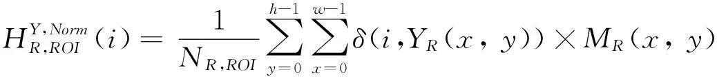
Histogram of an image can reflect the overall information of the image objectively. Color correction can be achieved if color information can be transferred more precisely from the reference image to the distorted image. In the proposed method, an image is converted from RGB color space to a less correlated YCbCr color space, and then normalized histograms and cumulative histograms of ROI and ROB are calculated respectively. Finally the cumulative histograms are used to obtain a mapping function between the reference image and the distorted image so as to achieve color correction between the corresponding regions. Since color correction process is the same for ROI and ROB with respect to the three channels of color space, here this paper just gives the implementation of color correction of ROI of the distorted image in luminance channel.
(3)
(4)
where m≤Ymax, Ymaxand Yminare the maximum and minimum amplitudes of the luminance channel Y of the ROI respectively.
(5)
with the constraint condition that
(6)
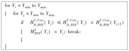
Fig.2 Histogram matching of Y channel
Then ROI of the corrected image can be obtained from the mapping function. The luminance signal of the corrected image can be calculated by
(7)
where YD(x, y) is the luminance of pixel (x, y) in the distorted image, and MD(x, y) with respect to pixel (x, y) of the distorted image should be 1 which means that the pixel belongs to ROI.
The correction of other two chrominance channels of ROI is the same with that of luminance channel Y, and the process of correcting ROB of image is also similar to that for ROI.
2 Experimental results
In order to test the effectiveness of the proposed method, two groups of microscopic images are chosen as shown in Fig.3(a)~Fig.3(d). All the experiments are tested on a PC with Windows 7 system, and the processor is Inter(R) Core(TM) i3 CPU@3.0GHz with 2.0G RAM. The Visual Studio 2010 software is used in the experiments, and all the source code is implemented with C/C++ language. The experimental results of the proposed method are compared with other three methods which are involved in Refs[4], [5] and [12], respectively. Table 1 gives the corresponding indexes of the three methods which will be used in the followed given experimental results.
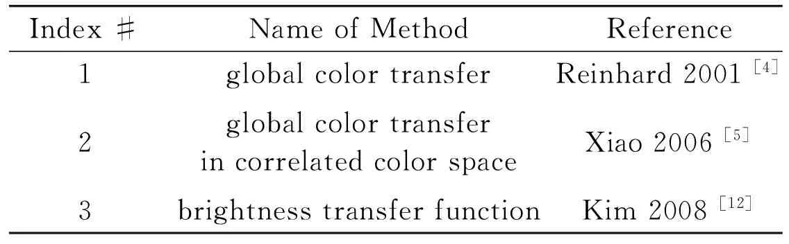
Table 1 Color correction methods for comparison
In this paper, average color deviation is used to evaluate the performance of different color correction methods. It is defined in CIE1976Lab color space. The average color deviation between reference image and corrected image can be defined by
(8)

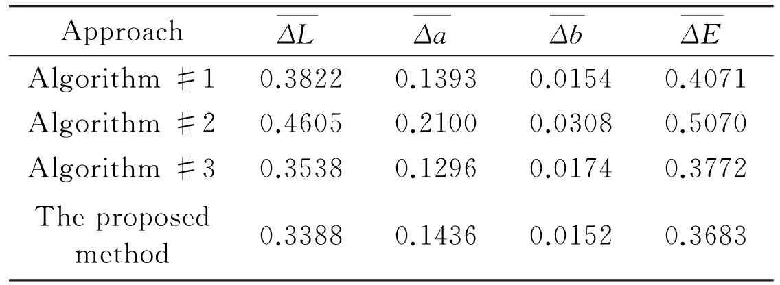
Table 2 Color deviation comparison of different color correction methods
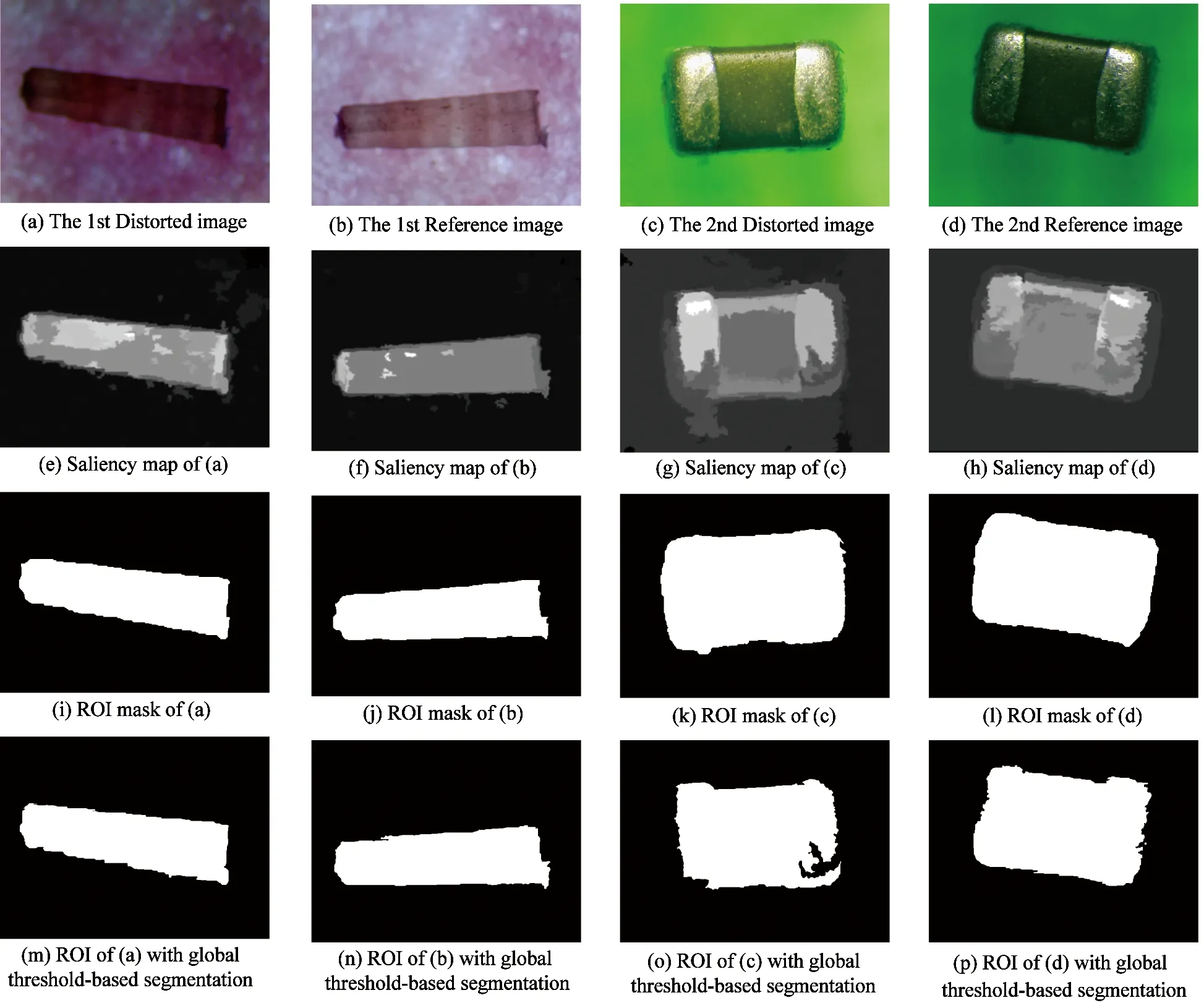
Fig.3 ROI segmentation of distorted images and reference images
Figs3(e)~3(h) show the saliency maps of color images in Figs3(a)~3(d), the ROI masks in Figs3(i)~3(l) are corresponding to the saliency maps after segmentation through auto-Grabcut method with four iterations. It is seen that edges of object in color image can be precisely located with the used segmentation method, and there is no under-segmentation and over-segmentation. By contrast, Figs3(m)~(p) also give the segmentation results obtained with global threshold-based segmentation method, which are clearly rough than the results of auto-Grabcut method used in the proposed method. Fig.4 shows two groups of corrected images obtained with the four different color correction methods. Figs4(a)~(d) are corrected from Fig.3(a) with the proposed method and the other three methods, and Figs4(e)~(h) are corrected from Fig.3(c). For the three methods used to be compared, color of each pixel in the distorted image must be calculated, thus new colors may be introduced and great color distortions may still exist in the corrected images. By contrast, the proposed method can precisely transfer color information of the reference image to the distorted color image at different regions, therefore, the color consistency between reference image and the corrected image can be ensured. The methods, which are involved in Refs[4,5], only use the mean and variance information to achieve color correction. The method in Ref.[12] only uses the luminance signal to get the Brightness Transfer Function (BTF) to achieve color correction. The three methods easily result in the lost of details in color correction process so that the corrected image may be over-smoothed.
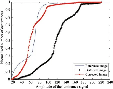
It is well known that histogram can objectively reflect the color information of an image. For two images with the same content, the histogram of them will be similar if the colors or luminance of them are similar with each other. Fig.5 shows the normalized and cumulative histograms of the corrected image compared with that of the reference image and the distorted image, where the corrected image, the distorted image and the reference image are shown in Fig.4(d), Fig.3(a) and Fig.3(b) respectively. From Fig.5, it is seen that the proposed method can achieve good color correction result. The normalized histogram and cumulative histogram of the corrected image is much closer to that of the reference image compared with that of the distorted image.
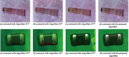
Fig.4 Color correction results with respect to different methods


Fig.5 Normalized histogram and cumulative histogram of the corrected image compared with that of the reference image and the distorted image separately
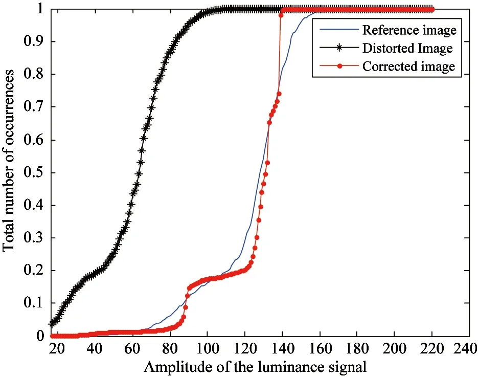
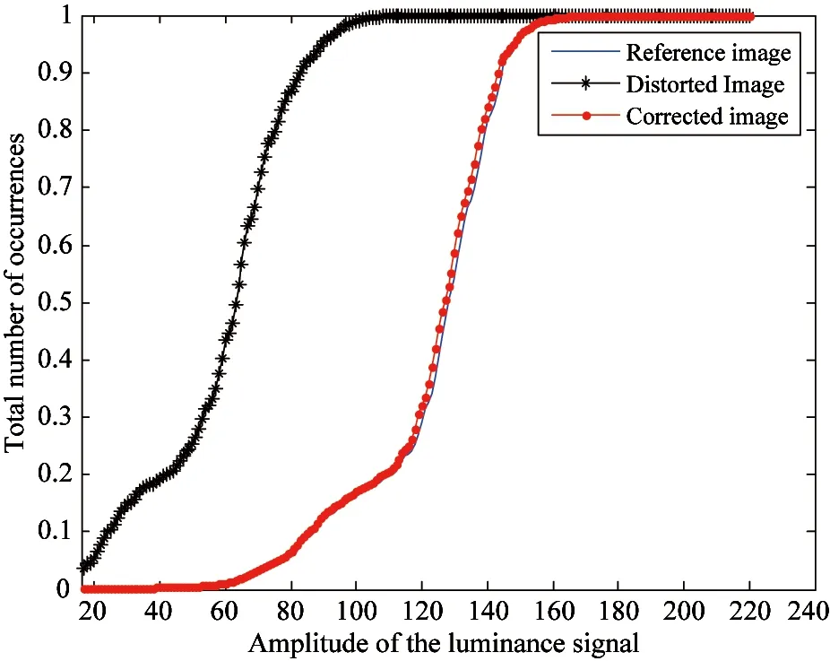
Fig.6 and Fig.7 give cumulative histograms of the corrected image (shown in Fig.4), the distorted image and the reference image with respect to the above four mentioned methods. Fig.6 is the results of Fig.3(a) and Fig.3(b), while Fig.7 is for Fig.3(c) and Fig.3(d). It is seen that the cumulative histograms of the corrected images obtained with the proposed method are much closer to that of the reference image, which means that the corrected image obtained with the proposed method keeps good consistent with the reference image in colors.
The methods based on global color transfer idea do not consider the difference between ROI and ROB, this may result in transfer error and some details in image may be lost during the transfer process. In the proposed method, cumulative histogram matching is used to get the color transfer functions. Since color cumulative histogram can reflect the statistical properties of the image color, the color information in reference image can be precisely transferred to the distorted color image. As a result, the proposed method has a higher stability. In the process of the proposed method, only the existed color in the reference image is transfered to the distorted image, so the color transfer process does not produce any new colors. From the experimental results, it can be easily found that there are many unexpected colors in the corrected color images obtained with the other three color correction methods. By contrast, the color statistical properties of the corrected image obtained with the proposed method is close to that of the reference image. In a word, the proposed method can achieve good color correction results.

(a) Algorithm #1[4]

(b) Algorithm #2[5]
(c) Algorithm #3[12]
(d) The proposed method

(a) Algorithm #1[4]
(b) Algorithm #2[5]

(c) Algorithm #3[12]
(d) The proposed method
3 Conclusions
Color difference resulted from image acquisition in stereomicroscope is a big problem needed to be solved since it will affect the efficiency of the followed image processing. In this paper, a ROI based color correction method using cumulative histograms is proposed. The color information of ROI and ROB is transferred separately in the color correction process. Such separately transfer treatment can effectively avoid error color transfer among different regions and thus the color correction accuracy can be improved by the proposed method.
[ 1] Ersoya O, Sena E, Aydar E, et al. Surface area and volume measurements of volcanic ash particles using micro-computed tomography (micro-CT): A comparison with scanning electron microscope (SEM) stereoscopic imaging and geometric considerations. Journal of Volcanology and Geothermal Research, 2010, 196(3-4):281-286
[ 2] Elbuken C, Khamesee M B, Yavuz M. Design and Implementation of a Micromanipulation System Using a Magnetically Levitated MEMS Robot. IEEE/ASME Transactions on Mechatronics, 2009, 14(4): 434-445
[ 3] Veikko S, Jääskeläinen M, Zhou Q. Hybrid Microassembly Combining Robotics and Water Droplet Self-Alignment. IEEE Trans. on Robotics, 2010, 26(6):965-977
[ 4] Reinhard E, Adhikhmin M, Gooch B, et al. Color transfer between images. IEEE Computer Graphics and Applications, 2001, 21(5):34-41
[ 5] Xiao X, Ma L. Color transfer in correlated color space. In: Proceedings of 2006 ACM International Conference on Virtual Reality Continuum and Its Applications, Hong Kong, China, 2006. 305-309
[ 6] Brown M, Lowe D G. Automatic panoramic image stitching using invariant features. International Journal of Computer Vision, 2007, 74(1):59-73
[ 7] Goldman D B, Chen J. Vignette and exposure calibration and compensation. In: Proceedings of the 10th IEEE International Conference on Computer Vision, Beijing, China, 2005. 899-906
[ 8] Litvinov A, Schechner Y. Addressing radiometric non-idealities: A unified framework. In:2005 IEEE Computer Society Conference on Computer Vision and Pattern Recognition, San Diego, USA, 2005. 2:52-59
[ 9] An K, Sun J, Zhou L. A linear color correction method for compressed images and videos. IEICE Transactions on Information and Systems, 2006, 89-D(10):2686-2689
[10] Xiang Y, Zou B, Li H. Selective color transfer with multi-source images. Pattern Recognition Letters, 2009, 30(7):682-689
[11] Jia J, Tang C. Tensor voting for image correction by global and local intensity alignment. IEEE Transactions on Pattern Analysis and Machine Intelligence, 2005, 27(1):36-50
[12] Kim S J, Pollefeys M. Robust radiometric calibration and vignetting correction. IEEE Trans. on Pattern Analysis and Machine Intelligence, 2008, 30(4):562-576
[13] Tanaka G, Suetake N, Uchino E. Color transfer based on normalized cumulative hue histograms. Journal of Advanced Computational Intelligence and Intelligent Informatics, 2010, 14(2):185-191
[14] Yamamoto K, Oi R. Color correction for multi-view video using energy minimization of view networks. International Journal of Automation and Computing, 2008, 5(3):234-245
[15] Guan Y, Cai Y, Zhang X, etc al. Adaptive correction technique for 3D reconstruction of fluorescence microscopy images. Microscopy Research and Technique, 2008, 71(2):146-157
[16] Shi C, Zhang L. A 3D shape measurement system based on random pattern projection. In: Proceedings of the 5th International Conference on Frontier of Computer Science and Technology, Changchun, China, 2010.147-153
[17] Rother C, Kolmogorov V, Blake A. Grabcut - Inter-active foreground extraction using iterated graph cuts. ACM Transactions on Graphics, 2004, 23(3):309-314
Jiang Gangyi, born in 1964. He received his M.S. degree from Hangzhou University in 1992, and received his Ph.D. degree from Ajou University, Korea, in 2000. He is now a professor at Faculty of Information Science and Engineering, Ningbo University, China. His research interests mainly include digital video compression and communications, multi-view video coding and image processing.
10.3772/j.issn.1006-6748.2015.03.006
①Supported by the Natural Science Foundation of China (No. 61311140262, 61171163, 61271021).
②To whom correspondence should be addressed. E-mail: jianggangyi@126.com Received on May 25, 2014***, Liu Xiangjun*, Yu Mei*, Peng Zongju*, Shao Feng*
猜你喜欢
心声歌刊(2022年1期)2022-06-06
新课程·上旬(2021年33期)2021-09-08
华人时刊(2020年17期)2020-12-14
大观(2019年3期)2019-08-01
文学教育下半月(2019年2期)2019-03-18
视野(2009年4期)2009-06-10
 High Technology Letters2015年3期
- High Technology Letters的其它文章
- Probability density analysis of SINR in massive MIMO systems with matched filter beamformer①
- An energy-saving scheduling scheme for streaming media storage systems①
- Design and analysis on four stage SiGe HBT low noise amplifier①
- Diversity-multiplexing tradeoff of half-duplex multi-input multi-output two-way relay channel with decode-and-forward protocol①
- Edge detection of magnetic tile cracks based on wavelet①
- Probabilistic data association algorithm based on ensemble Kalman filter with observation iterated update①