
Direct calculation method of roll damping based on three-dimensional CFD approach*
2015-04-20 05:52ZHOUYaohua周耀华MANing马宁SHIXun石珣ZHANGCheng章程
水动力学研究与进展 B辑 2015年2期
ZHOU Yao-hua (周耀华), MA Ning (马宁), SHI Xun (石珣), ZHANG Cheng (章程)
1. School of Naval Architect, Ocean and Civil Engineering, Shanghai Jiao Tong University, Shanghai 200240,China 2. Shanghai Rules and Research Institute, China Classification Society, Shanghai 200135, China,E-mail: yhzhou@ccs.org.cn 3. State Key Laboratory of Ocean Engineering, Shanghai Jiao Tong University, Shanghai 200240, China
Introduction
How to effectively estimate the roll damping of a ship is a very important issue, which concerns the application of the motion prediction theory in the ship design process for a long time. The prediction of the roll is the key in the dynamic stability failure models such as for the parametric rolling or the excessive acceleration, and the validity of the prediction of the full scale ship will be significantly dependent on the accuracy of the roll damping.
In a theoretical simulation, the roll damping due to its induced factors is usually divided into several parts[1], and the Ikeda’s method[2]is the most widely used, with a conventional empirical formula. In resent years, a great progress was made in the direct calculation of the roll damping based on the CFD approach.Huang et al.[3], Zhu et al.[4]and Luo et al.[5]carried out simulations of the forced roll motion of a 2-D ship section, with a good agreements with experimental results. Yang et al.[6,7]extended such method to the 3-D simulation of the S60, moving with or without a forward speed. Ji and Zhu[8]carried out the 2-D simulation of the roll decay for a barge section without a forward speed. 3-D roll decay simulations of a surface combatant were carried out by Wilson et al.[9]based on 6 DOF unsteady RANS method. The simulations of the combatant were performed for bare hull and bare hull with bilge keels. In the Gothenburg 2010 Workshop,simulations[10]of the free decay of the US combatant DTMB 5415 based on four codes were compared with experiments. The simulations were carried out for bare hull with bilge keels at a forward speed. The contour of the velocity of the flow around the bilge keels was also compared with that determined by the PIV experiment.
This study carries out simulations for the roll damping, based on the CFD solver ISIS-CFD[11]. Bysolving the 3 or 6 DOF motions, the decay curve of the free decay could be simulated in the calm water at zero velocity, and the roll damping coefficients could be estimated by processing the experimental data. In order to verify the effectiveness of this method, more simulations of different types of ship models than the previous studies are carried out and compared with the results of experiments. The types of ship models include the trimaran, the combatant and the containership with or without bilge keels. Good agreement with experimental results is achieved.
1. Theoretical formulation and numerical method
The flow solver concerns the incompressible unsteady Reynolds-averaged Navier Stokes (RANS)equations and is based on the finite volume method to build the spatial discretization of the transport equations. The face-based method is generalized to 3-D unstructured meshes, for which non-overlapping control volumes are bounded by an arbitrary number of constitutive faces. The flow solver deals with multi-phase flows and moving grids. In the multi-phase continuum,with consideration of the incompressible flow of viscous fluid under isothermal conditions, the mass, momentum and volume fraction conservation equations can be written as (using the generalized form of Gaussʼ theorem)[12]:
whereVis the control volume,Sis the surface ofV,are the density and the viscosity of the effective flow,Uis the velocity,pis the pressure;Udis the moving velocity ofS,ijτis the components of the viscous stress tensor,giis the gravity vector.
The closure of the Reynolds-averaged equations requires the definition of the turbulent Reynolds stresses. For incompressible flows, and if the isotropic part of the Reynolds stress tensor (2K/3) is not explicitly needed, then the stress tensor can be written as:
The pressure field is obtained from the mass conservation constraint, which is transformed into a pressure equation and the velocity field is obtained from the momentum conservation equations. In the case of turbulent flows, additional transport equations for modeled variables are solved in a form similar to that of the momentum equations and they can be discretized and solved using the same principles. Thek-omega(SST-Menter) turbulence model is used in the RANS solver, and the adaptive grid refinement method (refinement-de-refinement, parallel, unsteady and with load balancing) is adopted for capturing the free surface. The 6 DOF motion equations are directly based on Newton’s second law. The forces due to the interaction between the ship and the fluids (water and air)are calculated by integrating the three dimensional pressures of the fluids for the hull surface of the ship and updated every time step, then the motions could be solved.

The roll, the pitch, and the heave are the most important DOFs for the free decay of the ship. In the solution process, the Newton’s law and the RANS equations solver are used and the flow/motion coupling is updated each non-linear iteration until a converged solution of each time step is reached. Then the pressure of the water/air will be calculated for every cell and integrated on the hull of the ship for every DOF.
2. Analyses of numerical results
2.1 Ship models
Four ship models of different types are used in the numerical simulation, including the S175, the 3100TEU containership, the Warship and the Concept Trimaran.
The S175 is a public experimental model, without bilge keel or rudder. The 3100TEU is commercial ship still in service, with bilge keels and rudder insta-lled in the model. A series of seakeeping and maneuverability tests for these two containerships are conducted by Prof. Ma Ning of Shanghai Jiaotong University for research purposes.
Table 1 Principal dimensions
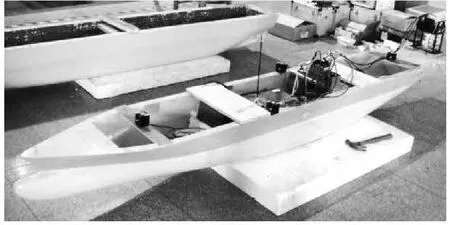
Fig.1 The ship model of the 3100TEU containership
The Warship is a model of combatant published by RINA[13], and installed with bilge keels, rudders and stabilizer fins. The Concept Trimaran is a Concept ship developed by Harbin Engineering University[14]for research purposes. Table 1 shows the principal dimensions of the four models. Figure 1 shows the 3100TEU.
2.2 Parameter settings and mesh generation
Figure 2 shows the geometry and meshes of typical sections.
(1) Parameter settings:
In this paper, the 3-D CFD approach is adopted for the simulation of the free rolling experiment, and the roll damping is calculated by processing the conventional experimental data. The scales and the geometries of the numerical models for the simulation are the same as the experimental ones, and it is necessary to make sure that the boundary of the numerical model is proper to avoid the numerical wave reflection effect.According to the comparison between the simulation and the experimental data, and the numerical test, the following scales are adopted. In the translational coordinate, the length of the computation domain is 3 times the model length, the depth of the domain is 1.3 times the model length, the domain is filled with water and air and the distance from the calm water free surface to the bottom of the domain is one model length,the breadth of the domain is 6 times the model length.
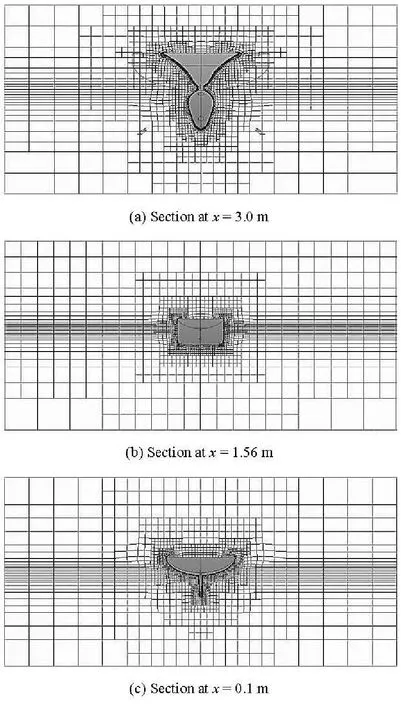
Fig.2 Meshes of typical sections of the 3100TEU containership
All predictions are obtained on the 0.79M-1.2M grid, depending on whether the model installed with or without appendages. The size of the grid near the free-surface is taken asLpp/300 in the vertical direction andLpp/20 in the other two directions.
(2) Motion simulations:
According to the test mode of the experimental data for the verification, two CFD methods are used in present study to simulate the motion of the roll decay.For the model tested by the 4 DOF measuring equipment in the towing tank (the roll, the pitch and the heave are free, the surge is constrained), the numericalsimulation is based on solving 3 DOF motions (the roll, the pitch and the heave), for the self-propulsion model tested in seakeeping tank, due to the fact that all 6 DOFs are free for the model test, so the numerical simulation is also based on solving 6 DOF motions.Of course, the influences of the DOFs such as the surge, the sway and the yaw will be small for the simulation at the zero hull speed.
The initial heel angle is set to the experimental value, and the initial velocity and acceleration are zero,the same as the experimental parameters.
The settings of the roll moment of inertia and the time step are as follows:
The roll moment of inertiaIxxand the time step are two key parameters as far as the accuracy of the numerical simulation is concerned.
The period of the free rolling is the natural roll period, which depends on the value ofIxxandGM.The estimation ofGMfor the model test or for a full scale ship could be made with a very high accuracy,but the measurement or calculation ofIxxis usually very difficult for both the model test or a full scale ship. Sometimes, the error ofIxxis quite significant.Therefore, the time history of the roll decay will be sensitive to the accuracy ofIxx. The numerical tests show that the low accuracy ofIxxcould make the roll cycle significantly deviate from the test results. For the numerical reproducibility of the simulations of the model test, the accuracy of the roll moment of inertia measured by the bench test is not satisfactory, therefore, the roll moment of inertia should be obtained from the measured natural period in a calm water, and the following formula[15]could be used:
whereTis the natural period of roll,Ixxis the roll moment of inertia, ΔIxxis the added roll moment of inertia,Mis the mass,GMis the metacentric height,gis the gravity acceleration. The value of ΔIxxcould be estimated by the 3-D frequency domain potential theory at zero speed, and the period of the incident wave is equal to the natural period measured by tests.
The time step Δtis also very important in determining the roll decay motion. Improper time step will lead to accumulation of errors of the numerical results of the fluid field during the calculation, and finally affect the divergence of the motion solution. The selected time step should be smaller than the allowed maximum time step to achieve an acceptable accuracy.The comparison between the measured roll decay curve of the S175 and the numerical one indicates that the excessive time step could lead to a significant error accumulation, and seriously affect the results of the motion. Furthermore, the error accumulation even might make the amplitude of the roll cease to decay.Comparisons between the simulations and the test results indicate that 320-360 time steps per roll period(Tφ) could basically ensure an acceptable simulation accuracy. The maximum number of non-linear iterations is taken as 8, and the convergence criteria are taken as to keep 2 orders of magnitude. For about 99.24% cells, the courant number is from 0.1212×10⁻⁵to 0.82534.
2.3 Verification of numerical approach
The numerical simulations of the S175 and the 3100TEU are based on solving 6 DOF motions, and those of the Warship and the Concept trimaran are based on solving 3 DOF motions.
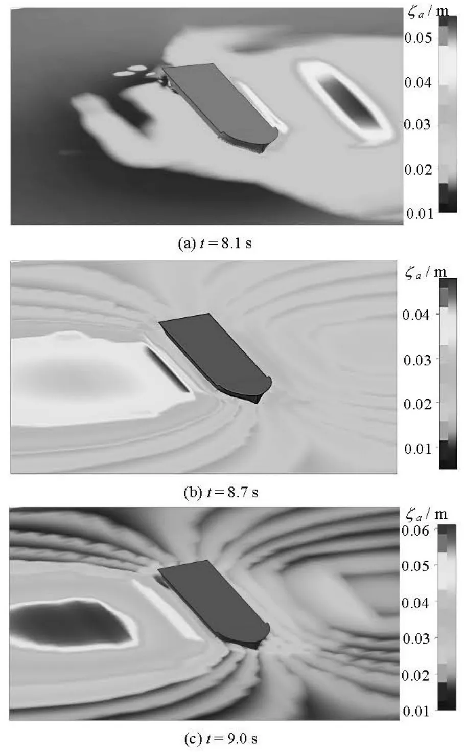
Fig.3 Free surface height round 3100TEU
The roll damping is usually divided into several components, including the contributions of the wave,the lift, the friction, the eddy and the appendages. The damping contributions from the wave and the lift arelinear, and those from the friction, the eddy and the appendage are nonlinear. For the simulation of the roll damping at zero speed, the lift damping could be ignored. The calculation of the other components depends on the precision of the prediction of the motions.The adoption of a 3-D approach means that the interaction between the sections of the ship and the free surface could be included in the simulations. This is an obvious advantage as compared with a 2-D approach.Figure 3 shows the free surface round the 3100TEU in a free decay. The development of wave troughs and crests at the broadside due to the radiation could be observed clearly.
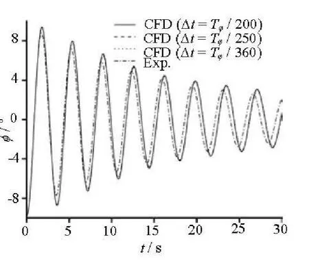
Fig.4(a) The free decay of 3100TEU for different time steps seeting
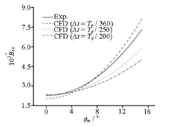
Fig.4(b) of 3100TEU (Eq.(13a)) for different time steps setting
Fig.4(c) The free decay of 3100TEU for different mesh settings
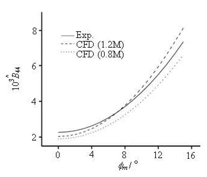
Fig.4(d) of 3100TEU (Eq.(13a)) for different mesh settings
First of all, the appropriate time step and mesh settings are analyzed. Figure 4(a) shows the comparison of the free decay histories of the CFD simulations of the 3100TEU. The setting of the time step varies from 200 to 360 time steps per roll period. The simulated natural roll period is very consistent, but the amplitude of the roll varies with different time step settings. The time histories of the simulations with different settings are similar. However, according to the comparisons of the simulated equivalent roll damping for different time step settings as shown in Fig.4(b),the influence of the time step is very significant.
A comparison of the 3100TEU is also made for two different meshes. As shown in Fig.4(c), the natural roll period calculated by a mesh with smaller grids is more close to the tested period. This is because the accuracy of the period is also affected by the roll moment of inertia. The free decay of the roll depends on the value ofIxxand the addedIxx. However, the roll moment of inertia is estimated by Eq.(6) and is difficult to measure accurately, so the error ofIxxis inevitably included in the RANS simulation. This also explains why the natural roll period of the 3100TEU calculated by the 3-D model without the rudder (as shown in Fig.6(b)) is more close to the tested period.In addition, the equivalent roll damping curves (as shown in Fig.4(d)) indicate that the accuracy is improved with the modification of mesh.
According to the analysis of the time history of the free decay and the equivalent roll damping, the appropriate time step and grid are decided for further simulations. Of course, better agreement could be achieved if more computational resources are used,which will not be discussed in this paper.
2.4 Validation and analysis of results
In order to investigate the effect of the rudder on the roll damping, two numerical simulations for the models with rudder and without rudder are carried out and compared. Figure 5 shows the difference of themodels.
From the time history of the free rolling decay obtained by the CFD simulation, the conventional experimental data processing method is used for estimating the extinction coefficient. Due to the “noise” of the experimental data, the time histories of the free decay need to be smoothed before the calculation. The following method[16]could be adopted.

With the smoothed time history of the roll, the peak value of the roll φkand the extinction curvecould be estimated.

For largemφ, the extinction curve could be fitted with the following function
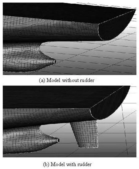
Fig.5 3-D models of 3100TEU with/without rudder

Then the extinction coefficient[13]is
For smallmφ, the extinction curve could be fitted as a linear curve, and then the extinction coefficient is
The roll moment due to the roll damping is
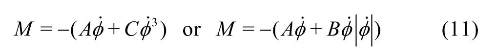
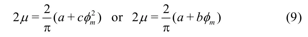
where

are the damping coefficients, φ is the angular velocity of the roll, a, b, c, are the extinctive coefficients in Eq.(8b), and they can be determined by fitting the experimental data, W is the gravity of the ship,φω is the natural roll frequency.
Therefore, the equivalent linear damping could be determined based on the principle of conservation of energy. For a half cycle, there are
Then, the equivalent linear damping isis non-dimensionalized as follows

where ρ, ▽ and B denote the mass density of the fluid, the displacement volume and the breadth of the ship’s hull, respectively. Figure 6 shows the roll decay curves of the S175 and the 3100TEU, including the comparisons between the experimental data and the si-mulations. Figure 7 shows the CFD simulation results of the Warship and the Trimaran.
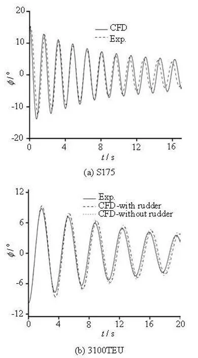
Fig.6 The time histories of free rolling of S175 and 3100TEU(Fr=0)

Fig.7 The time histories of free rolling of Warship and Trimaran (Fr=0)
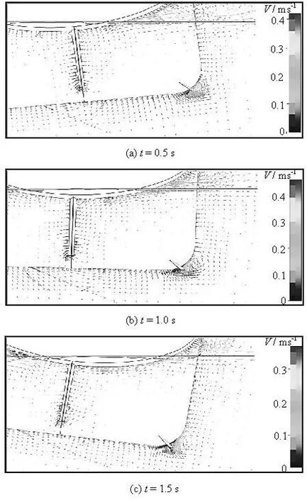
Fig.8 Velocity vectors of 3100TEU for roll decay
Figure 8 shows the velocity vectors around the bilge keel and rudder of the 3100TEU. In different stages of the free rolling, the vortex around the bilge keel is significantly stronger than that around the rudder, which means that the rudder’s ability to induce eddy is weaker than the bilge keel. The deviation of the time histories of the cases with and without the rudder seems to be small (as shown in Fig.5). But according to the comparisons of the extinction coefficient of the 3100TEU (as shown in Fig.9), although the effect of the rudder on the roll damping is weaker than that of the bilge keels at zero velocity, the influence of the rudder could not be ignored. The friction, the eddy and the appendage components are nonlinear with respect to the damping. As shown in Fig.8, the rudder induces obvious vortex, therefore, the value of 2μof the CFD model with the rudder is larger than that without the rudder, especially for largemφ. This means that the accurate modeling of appendages such as the rudder is still necessary for a better numerical simulation.
Figure 9 shows the history of the non-dimensional roll moment obtained by the simulation. The con-tributions such as of the wave, the frictional and the eddy are all included in the total roll moment. The results of the RANS are divided into two parts: the moments caused by the pressure and the shear. As shown in Fig.9, the moment caused by the pressure is always the main component during the free decaying. The simulated moment caused by the shear seems to be very small. This result is different from that of the 2-D simulation for a forced roll of a ship section[3], but it is more close to that of the 3-D simulation for the forced roll motion[7]. The results of the 3-D simulation for the forced roll indicate that the moment caused by the shear is much smaller than that caused by the pressure.In order to investigate this phenomenon, further research is still needed.
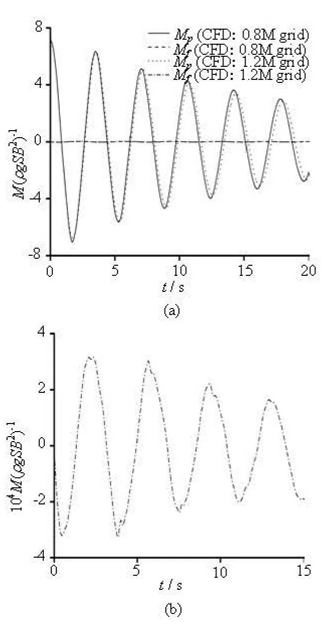
Fig.9 Time history of roll moment of 3100TEU
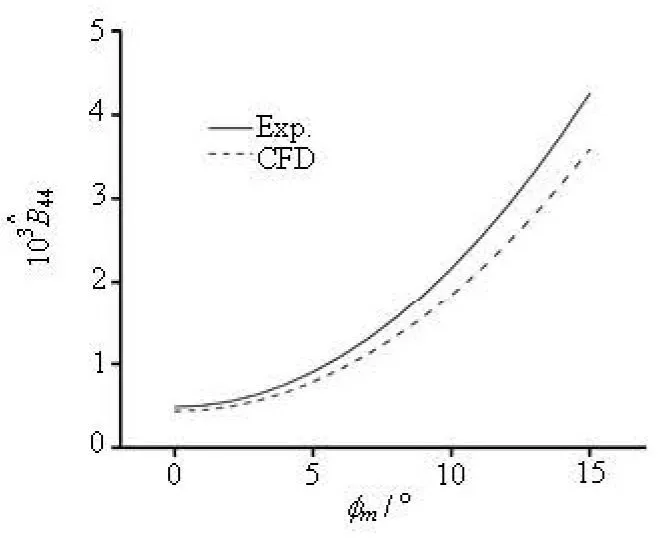
Fig.10(a) of S175 (Eq.(13a))
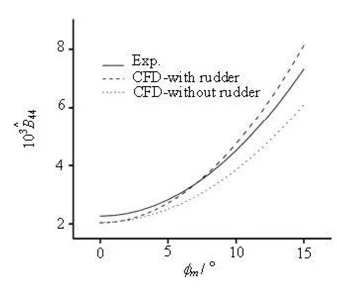
Fig.10(b) of 3100TEU (Eq.(13a))
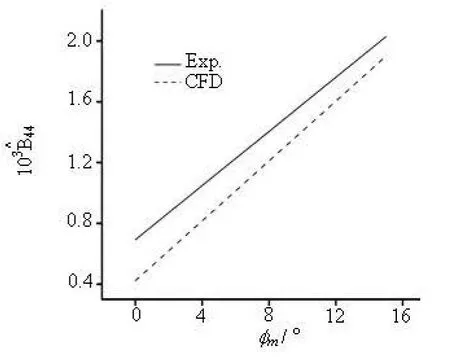
Fig.10(c) of S175 (Eq.(13b))
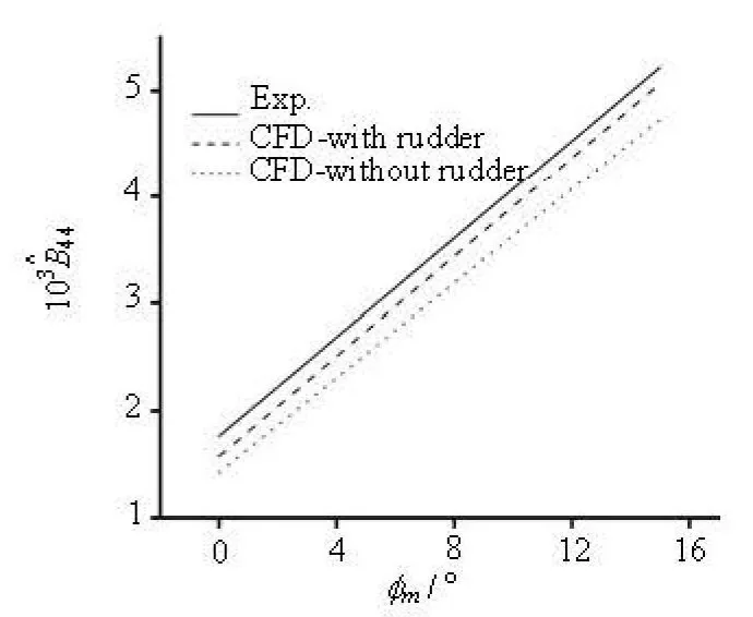
Fig.10(d) of 3100TEU (Eq.(13b))
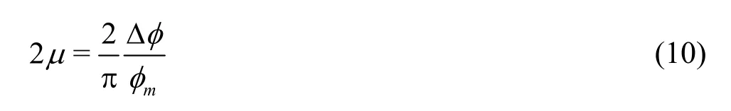
Figure 10 shows the equivalent damping of the S175 and the 3100TEU. In Table 2, the natural roll periods and the extinction/damping coefficients of the S175, the 3100TEU, the Warship and the Concept Trimaran are compared between the CFD simulations and the experimental data. Equation (13) is used for the calculation of the extinction coefficients of the 3100TEU and the S175. Because only the linear expression of 2μis provided in the references, Eq.(10)is used for the calculation of the Warship and the Concept Trimaran.
As shown in Fig.6 and Table 2, a good accuracycould be achieved for the natural roll period. Moreover, with the increase of the number of rolling cycles,the errors of the time history due to the error accumulation are inevitable. By fitting the extinction curve,the comparisons ofand 2μindicate that as shown in Fig.10 and Table 2 that the CFD method used in this study could achieve a good agreement for the simulation of the free decay in calm water at zero velocity, and the errors are acceptable though there are some errors in the amplitude and the phase of the roll.
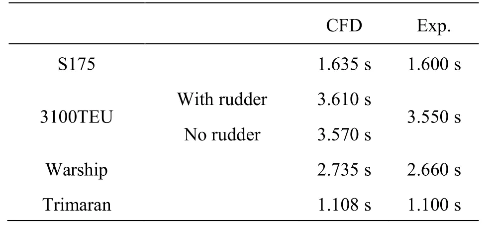
Table 2(a) The natural roll periods Troll
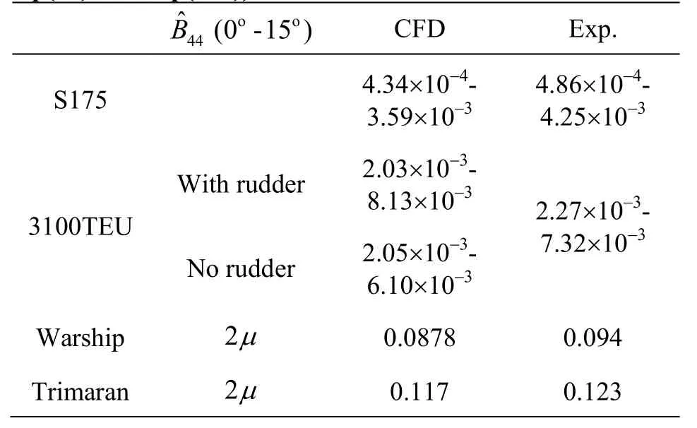
Table 2(b) The extinction/damping coefficients (based on Eq.(10) and Eq.(13a))
The extinction curve of the 3100TEU fits better than that of the S175. This is because the sample frequencies of the measuring instrument are fixed for both experiments. Due to the natural roll period of the S175 is much smaller than that of the 3100TEU, the effective data collected by the free decay experiment in a single period for the S175 are also fewer than those of the 3100TEU, therefore, the error of the measured roll amplitude of each period is larger (as shown in Fig.11). This is the main reason why the deviation of Δφgets more significant with the increase ofmφ,and one sees a less agreement of the 2μcurves between the CFD simulation and the experiment. On the other hand, in the CFD simulations a proper time step could be adopted for each model, so the accuracy could always keep at the same level and the time history of the roll decay is not affected by this sample frequency problem.

Fig.11(a) Fitting results of Extinction curves of 3100TEU

Fig.11(b) Time history of S175 and 3100TEU
According to the accident reports of full scale ships, the container ship may be vulnerable to dynamic stability failures such as the parametric rolling(with the loading condition usually of a relatively smallGMvalue) and the excessive acceleration (with the loading condition usually of a relatively largeGMvalue). The roll damping is very important for the simulation of these two phenomena, so the influence of theGMvalue on the damping characteristics of the container ship is worthy of studying. In order to analyze this issue for the 3100TEU, seven simulations with assumed VCG are carried out. This means that the loading conditions are all the same, except theGMvalues.

Fig.12(a) under the same loading conditions with assumed VCG (3100TEU)
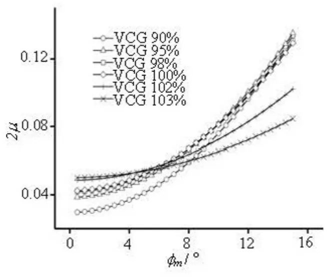
Fig.12(b) 2μ under the same loading conditions with assumed VCG (3100TEU)
As shown in Fig.12, for smallerφm, the value of 2μunder the loading conditions of smallerGMvalue is usually larger. But for largerφm, the variation tendency of 2μis reversed. This is because the extinctive coefficientaincreases with the increase of VCG, and on the other hand the extinctive coefficientcdecreases. The equivalent linear damping can also be calculated with Eqs.(11) and (13), and it is affected by the natural roll frequencies, which also depend onGM. It is shown that, forφmwithin less thano15,the maximum damping is achieved by an assumed loading condition with VCG smaller than that under the actual condition by 10%. Therefore, for this loading condition of the 3100TEU, it seems that a largerGMthan the existing design value could induce a greater roll moment of the roll damping for a larger roll amplitude.
The proposed method could ensure a steady accuracy for both mono-hull ships with/without appendages and the trimaran without appendages. Therefore, since this method is not sensitive to the types of ships, it could be further developed for forecasting the roll damping for a full scale ship and the optimization of design[17,18]. For the simulation of the loading condition of full scale ships, the conventional test method could be used. First, according to the loading condition, the parameters such as the roll moment of inertia and the center of gravity of the ship could be estimated. Then, the scaled 3-D model could be established,and for the parameter settings, the method developed in this paper could be used. Finally, with theIxxand addedIxxbeing calculated accurately according to the loading condition of the whole ship and the potential theory, a proper time step could be determined by the natural roll period for the numerical simulations.
3. Conclusions
3-D CFD calculations are carried out for the simulation of the free rolling decay of four models at zero velocity, and the obtained extinction coefficients of the roll are in a good agreement with those of the experiments. The developed direct roll damping calculation method based on numerical simulations of the free rolling decay is thus shown to be feasible. The following conclusions are drawn:
The simulations and comparisons are carried out for both mono-hull ships with/without complex appendages and the trimaran without appendages. It is shown that, the 3-D RANS method can be used to forecast the free decay and the roll damping, has a good applicability and enjoys a stable accuracy.
For the calculation of the roll damping, the accuracy of the roll moment of inertia and the selection of time step have a significant effect on the time history of the roll decay. For the numerical reproducibility of simulations of model tests, the values could be estimated by the measured natural roll period and with the help of potential theory tools. The vortex could be induced around the rudder at zero speed, so an accurate modeling of appendages such as rudder is still necessary for a better numerical simulation.
Under the same loading condition of the containership 3100TEU, an enlargedGMvalue is found to induce a greater roll moment due to the roll damping. Furthermore, the 3-D RANS approach could also be used in the study or the optimization of the dynamic stability of containerships in the future.
[1] CHAKRABARTI S. Empirical calculation of roll damping for ships and barges[J]. Ocean Engineering, 2001,28: 915- 932.
[2] KAWAHARA Y., MAEKAWA K. and IKEDA Y. A simple prediction formula of roll damping of conventional cargo ships on the basis of ikeda’s method and its limitation[J]. Journal of Shipping and Ocean Engineering, 2012, 2: 201-210.
[3] HUANG Hao, GUO Hai-qiang and ZHU Ren-chuan et al. Computations of ship roll damping in viscous flow[J]. Journal of Ship Mechanics, 2008, 12(4): 568-573(in Chinese).
[4] ZHU Ren-chuan, GUO Hai-qiang and MIAO Guo-ping et al. A computational method for evaluation of added mass and damping of ship based on CFD theory[J].Journal of Shanghai Jiaotong University, 2009. 43(2):198-203(in Chinese).
[5] LUO Min-li, MAO Xiao-fei and WANG Xiao-xia et al.CFD based hydrodynamic coefficients calculation to forced motion of two-dimensional section[J]. Chinese Journal of Hydrodynamics, 2011, 26(4): 509-515(in Chinese).
[6] YANG Chun-lei, ZHU Ren-chuan and MIAO Guo-ping et al. A roll damping prediction method of three-dimensional ships based on CFD computation[J]. Journal of Shanghai Jiaotong University, 2012. 46(8): 1190-1202(in Chinese).
[7] YANG Chun-lei, ZHU Ren-chuan and MIAO Guo-pinget al. Numerical simulation of rolling for 3-D ship with forward speed and nonlinear damping analysis[J]. Journal of Hydrodynamics, 2013, 25(1): 148-155.
[8] JI Dong-fang, ZHU Liang-sheng. Numerical simulation of ship free roll decay motion in viscous flow[J]. Science Technology and Engineering, 2009. 9(23): 7061-7065(in Chinese).
[9] WILSON R. V., CARRICA P. M. and STERN F. Unsteady RANS method for ship motions with application to roll for a surface combatant[J]. Computers and Fluids, 2006, 35: 501-524.
[10] LARSSON L., VISONNEAU M. CFD in ship hydrodynamics-Results of the Gothenburg 2010 workshop[C].The Gothenburg 2010 Workshop. Gothenburg,Sweden, 2010.
[11] DENG G. B., QUEUTEY P. and VISONNEAU M. Seakeeping prediction for a container ship with RANS computation[C]. The 9th International Conference on Hydrodynamics. Shanghai, China, 2010.
[12] ECOLE CENTRALE DE NANTES. Theoretical manual of ISIS-CFD v3.0[R]. Nantes, France: Universite De Nantes, 2012, 2-4.
[13] RINA. Wave induced motions and loads on a model warship[R]. London, UK: The Royal Institution of Naval Architects, 1980.
[14] ZHOU Yao-hua. The prediction of roll damping and nonlinear motion of trimaran[D]. Master Thesis, Harbin,China: Harbin Engineering University, 2010(in Chinese).
[15] LI Ji-de. Ship seakeeping performance[M]. Harbin,China: Harbin Engineering University Press, 2007, 34-35(in Chinese).
[16] MA Shan, CAO Yu and MA Wei-xing et al. Investigation of estimation method for roll damping from calm water free decay experiment using energy method[J].Journal of Ship Mechanics, 2012, 16(10): 1122-1130(in Chinese).
[17] IKEDA Y. Prediction methods of roll damping of ships and their application to determine optimum stabilization devices[J]. Marine Technology, 2004, 41(2): 89-93.
[18] TAYLAN M. Effect of forward speed on ship rolling and stability[J]. Mathematical and Computational Applications, 2004, 9(2): 133-145.
猜你喜欢
水土保持通报(2022年5期)2023-01-03
船舶经济贸易(2022年10期)2022-11-03
水土保持通报(2022年3期)2022-10-16
中国典型病例大全(2022年11期)2022-05-13
——江苏邳州老年大学校歌
老年教育(老年大学)(2020年10期)2020-10-22
流行色(2019年7期)2019-09-27
高中生·天天向上(2018年3期)2018-04-14
产品可靠性报告(2017年5期)2017-08-30
新校长(2015年11期)2015-02-27
西华大学学报(哲学社会科学版)(2014年3期)2014-02-27

- 水动力学研究与进展 B辑的其它文章
- A general framework for verification and validation of large eddy simulations*
- Visualization study on fluid distribution and end effects in core flow experiments with low-field mri method*
- Large-eddy simulation of the flow past both finite and infinite circular cylinders at Re =3900*
- Safe operation of inverted siphon during ice period*
- Flow field simulation of supercritical carbon dioxide jet: Comparison and sensitivity analysis*
- Ship hull optimization based on wave resistance using wavelet method*