
Optimal tracking control for automatic transmission shift process
2015-04-22 02:33WANGuoqiang万国强LIKeqiang李克强PEILing裴玲HUANGYing黄英ZHANGFujun张付军
WAN Guo-qiang(万国强), LI Ke-qiang(李克强), PEI Ling(裴玲),HUANG Ying(黄英),, ZHANG Fu-jun(张付军)
(1.State Key Laboratory of Automotive Safety and Energy,Tsinghua University, Beijing 100084, China;2.Laboratory for Integrated Power System Technology, Beijing Institute of Technology, Beijing 100081, China)
Optimal tracking control for automatic transmission shift process
WAN Guo-qiang(万国强)1, LI Ke-qiang(李克强)1, PEI Ling(裴玲)2,HUANG Ying(黄英), ZHANG Fu-jun(张付军)2
(1.State Key Laboratory of Automotive Safety and Energy,Tsinghua University, Beijing 100084, China;2.Laboratory for Integrated Power System Technology, Beijing Institute of Technology, Beijing 100081, China)
In order to improve the shift quality, a linear quadratic optimal tracking control algorithm for automatic transmission shift process is proposed. The dynamic equations of the shift process are derived using a Lagrange method. And a powertrain model is built in the Matlab/Simulink and verified by the measurements. Considering the shift jerk and friction loss during the shift process, the tracking trajectories of the turbine speed and output shaft speed are defined. Furthermore, the linear quadratic optimal tracking control performance index is proposed. Based on the Pontryagin’s minimum principle, the optimal control law of the shift process is presented. Finally, the simulation study of the 1-2 upshift process under different load conditions is carried out with the powertrain model. The simulation results demonstrate that the shift jerk and friction loss can be significantly reduced by applying the proposed optimal tracking control method.
powertrain; automatic transmission; shift process; optimal tracking control
Drivability and fuel economy arecontinuously emphasized during the development of automatic transmission[1-2]. The clutch-to-clutch shift control technology is the key enabler for a compact, light mass and low cost automatic transmission design, especially when the transmission has an extended number of speeds.
To improve the shift quality, a number of researches have focused on the clutch-to-clutch shift control technologies. D. Cho developed a clutch-to-clutch shift controller based on the sliding mode control[3]. To compensate for the effects of the life cycle and build-to-build variations, K. Hebbale and C. Kao presented a model reference adaptive controller[4]. T. Minowa et al. proposed anH∞controller to restrain the torque fluctuation when shift characteristics change occurs[5]. To minimize the performance measure, A. Haj-Fraj and F. Pfeiffer presented a model-based optimal control approach using a dynamic programming method[6]. To overcome the unmodeled dynamics or the variations of system characteristics, J. O. Hahn et al. proposed a self-learning algorithm for the inertia phase[7]. S. Watechagit and K. Srinivasan presented a model-based sliding mode observer to provide on-line estimates of the clutch pressures[8]. To enable a precise pressure-based control and avoid the chattering effect, Xingyong Song and Zongxuan Sun designed a sliding-mode controller[9]. Using the concept of input-to-state stability, Bingzhao Gao et al. presented a clutch pressure observer to improve the estimation accuracy during the torque phase[10].
To minimize the jerk and friction loss of shift process, a linear quadratic optimal tracking control method is proposed in this paper. The paper is organized as follows. A powertrain model is built and verified in Section 1. In Section 2, the optimal tracking control for automatic transmission shift process is proposed. Section 3 shows the simulation results. Conclusions are drawn in section 4.
1 Powertrain model
A powertrain system with automatic transmission consists of four components: engine, torque converter, planetary gearbox and output train, as shown in Fig.1. To analyze the shift process, the powertrain system can be simplified as a lumped mass multi-degree of freedom system. Each component of the powertrain can be considered as a rigid multibody subsystem. The rigid bodies are connected with each other by ideal rigid joints, clutches and force elements.
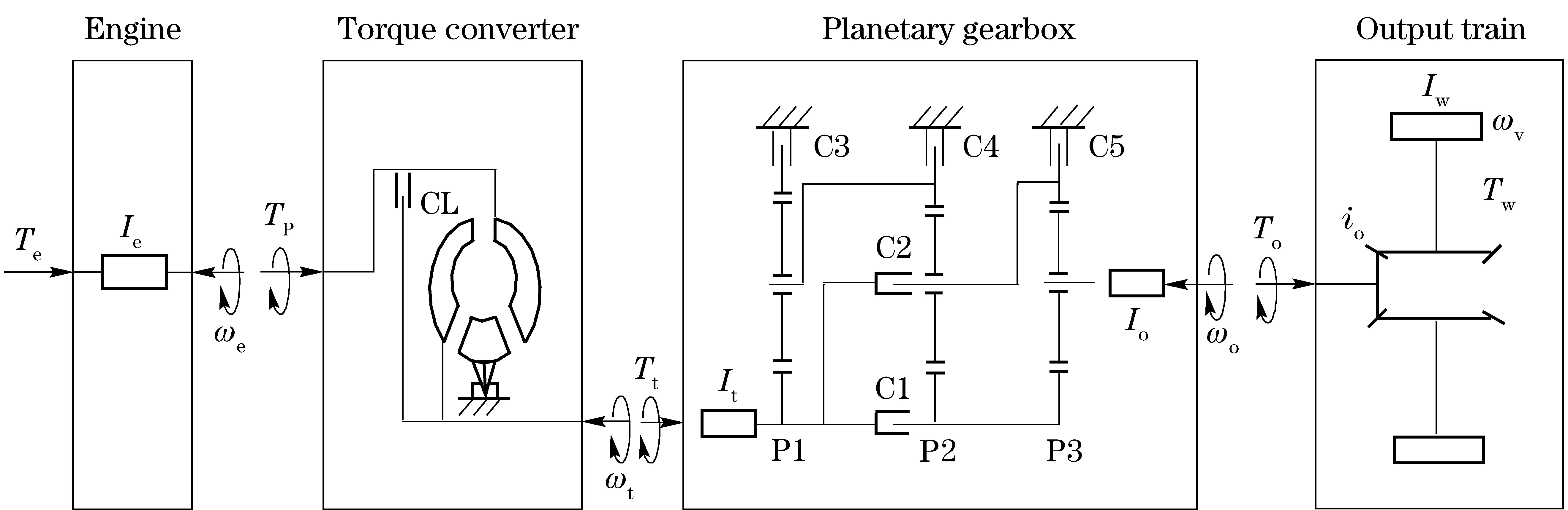
CL—the lockup clutch; C1-C5—the clutch/brake; P1, P2, P3—the planetary gear set
1.1 Engine
For investigation of the shift process, the high-frequency vibrations of the engine can be neglected. Therefore, the engine can be modeled as a rotating rigid body. The indicated torque of engine can be described by the following equation
Tin=mfHuηi
(1)
whereTinis the indicated torque of engine;mfis the fuel delivery per cycle;Huis the low heating value of diesel;ηiis the indicated thermal efficiency.
The effective torque of engine can be described as
Te=Tin-Tf
(2)
whereTeis the effective torque of engine;Tfis the friction torque of engine.
The equation of motion of the engine crankshaft can be written as
(3)
where Ieisthemomentofinertiaofcrankshaft;ωeis the engine angular velocity;Tpis the pump torque.
1.2 Torque converter
The pump torque and turbine torque can be obtained by
(4)
Tt=kTp
(5)
whereλis the pump torque coefficient;ρis the fluid density;gis the acceleration of gravity;Dis the equivalent diameter of torque converter;neis the engine speed;Ttis the turbine torque;kis the torque ratio of torque converter.
1.3 Planetary gearbox
The planetary gearbox consists of three planetary gear sets, two clutches and three brakes as shown in Fig.1. By the engagement of the clutches/brakes in various combinations, the planetary sets act singly or together to provide five forward ranges, neutral, and reverse. In the paper, the gear upshift from the first to the second gear will be considered. C1 and C5 engage to attain the first gear. During the 1-2 shift process, solenoid A energizes and exhausts clutch C5. Solenoid B energizes and engages clutch C4. C1 and C4 engage to attain the second gear. Solenoid A and solenoid B are pressures proportional to current solenoids. Varying currents to these solenoids changes the applied pressures to specific clutches. The currents of the solenoids are controlled by the powertrain control module.
Clutch C1 keeps engagement during the 1-2 shift process. To analyze the 1-2 shift process, the planetary gearbox can be further simplified as shown in Fig.2.
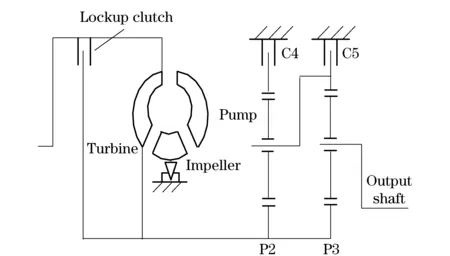
Fig.2 Simplified planetary gearbox diagram
1.3.1 Kinematics analysis
According to the motion property equation of planetary gear train, the following equations are obtained
(ki+1)ωPCi=ωSi+kiωRi(i=1,2,3)
(6)
(7)
where kisthegearratiobetweentheringgearandsungear; iistheserialnumberoftheplanetaryset;ωPCis the planet carrier angular velocity;ωSis the sun gear angular velocity;ωRis the ring gear angular velocity;ωPis planet pinion angular velocity.
Choosing the turbine angular velocityωtand the output shaft angular velocityωoas variables, according to Eqs.(6)(7),we obtain
(8)
1.3.2 Dynamic analysis based on the Lagrange method
In the paper, the Lagrange method was applied for the dynamic analysis of the 1-2 upshift process. The input shaft angleφtand output shaft angleφoare chosen as the generalized coordinates, that isq1=φt,q2=φo.
The virtual work of the system in terms of the virtual displacements is
∑δW=Tiδφt+TC4δφR2-TC5δφR3-Toδφo
(9)
where δWis the virtual work of the system;Tiis the input torque of gearbox;TC4is the friction torque of clutch C4;TC5is the friction torque of clutch C5;Tois the output torque of gearbox;φR2is the angle of R2;φR3is the angle of R3.
The generalized forcesQ1,Q2are defined as
(10)
(11)
Lagrangian functionLis defined as
L=K-V
(12)
whereKis the total kinetic energy of the system;Vis the total potential energy of the system.
Each planetary set has four pinions. In this case, there is no potential energy change due to the rotation of the pinions around the sun. Thus,V=0.
The kinetic energy of the system is
(13)
where IS2S3isthemomentofinertiaofS2,S3andtheconnectedshafts; IR2isthemomentofinertiaofR2andtheconnectedshaft; IPC2R3isthemomentofinertiaofPC2,R3andtheconnectedshafts;IPC3isthemomentofinertiaofPC3andtheconnectedshafts; IP2andIP3aretheequivalentmomentofinertiaofP2andP3.
Lagrange’sequationforthesystemis
(14)

(15)
Theequationofmotionoftheturbineshaftcanbedescribedas
(16)
whereIttheequivalentmomentofinertiaofturbineshaft.
NotethatclutchC4andclutchC5arebrakes,theirpassivefrictionplatesarefixed.ωR2andωR3are the relative speed of clutch C4 and C5, respectively. In this paper, the clutch C4 is taken as an example to demonstrate the torque characteristics of the wet clutch.
WhenωR2≠0, the clutch C4 slips. The friction torque is calculated as
TC4=-sgn(ωR2)μkApzrep
(17)
whereμkis the dynamic friction coefficient;Apis the area of piston surface;zis the number of friction surfaces;reis the equivalent friction radius;pis the clutch pressure.
Thedynamic friction coefficientμkis specified as a tabulated discrete function of the relative angular speedωR2.
μk=0.063 1+0.050 4exp (-0.033ωR2)
(18)
WhenωR2=0, the clutch C4 sticks. The static friction torque can be calculated as
TC4=μsApzrep
(19)
whereμsis the static friction coefficient.
1.4 Output train
The equation of motion of the wheels can be indicated as
(20)
where Iwisthemomentofinertiaofthewheels;ωwis the wheel angular velocity;iois the transmission ratio of the rear differential;Tois the output torque of gearbox;Twis the output torque of wheels.
TL=(Froll+Fwind+Fincl)r
(21)
whereFrollis the rolling force;Fwindis the wind force;Finclis the inclination force;ris wheel radius.
The equation of motion of the output train with the vehicle mass can be written as
(22)
where misvehiclemass.
Thewheelangularvelocityandoutputshaftangularvelocityhasthefollowingrelation
ωo=ioωw
(23)
1.5 Model verification
To develop and investigate the optimal tracking control for the shift process of automatic transmission, the powertrain system is built in the Matlab/Simulink. A two-stage, torque phase and inertia phase, control strategy is used during the 1-2 shift process. In the torque phase the open-loop control of the clutch pressure was applied[9], while in the inertia phase the feedback control based on the predetermined target turbine speed was adopted. The comparison between simulations performed with the presented model and the measurements carried out on the test bench during the 1-2 shift process under different load conditions shows a very good agreement, as shown in Fig.3 and Fig.4. Therefore the powertrain model can be used to develop a model-based optimal tracking control for the shift process. Moreover, the simulation results of the two-stage control will be regarded as the reference in the following section.
MRI试验主要参数:重复时间TR=1000 ms;矩阵256×256;信号接收带宽SW=40 kHz;采样次数NS=4;根据CPMG序列测得的T2值,选择回波时间TE=1 ms进行成像,采集数据,同时,通过调整MSE序列中的选层梯度、相位编码梯度和频率编码梯度,获取样品侧视成像数据[11]。
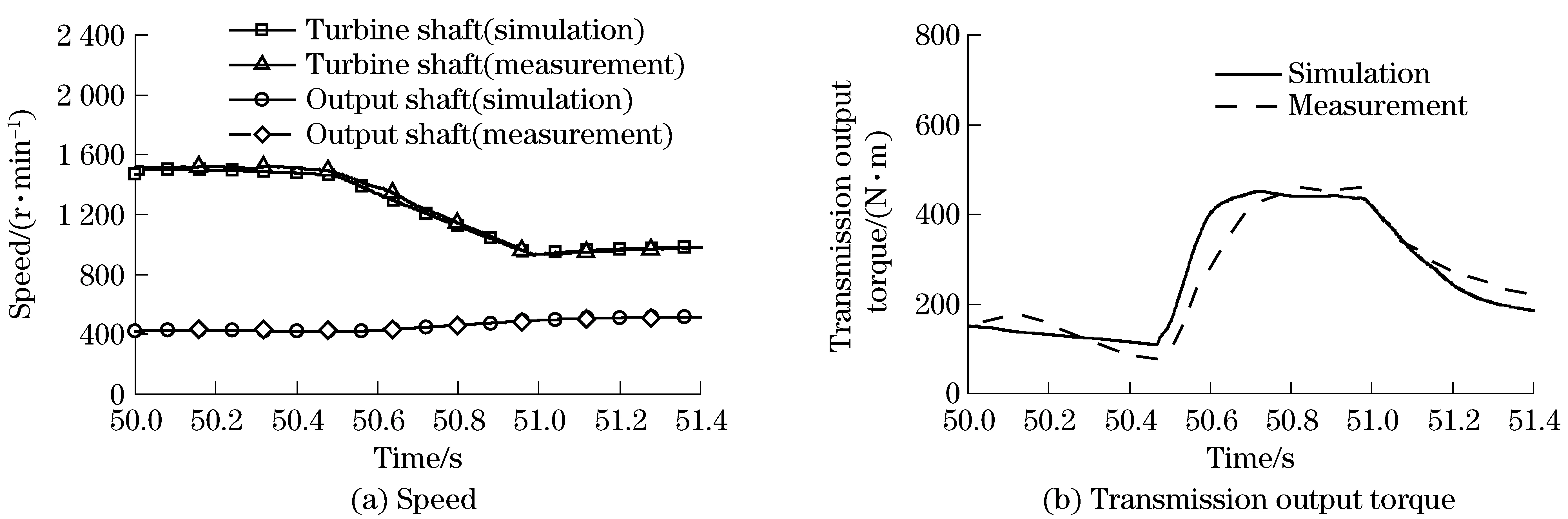
Fig.3 Comparison of simulations and measurements, TL=750 N·m
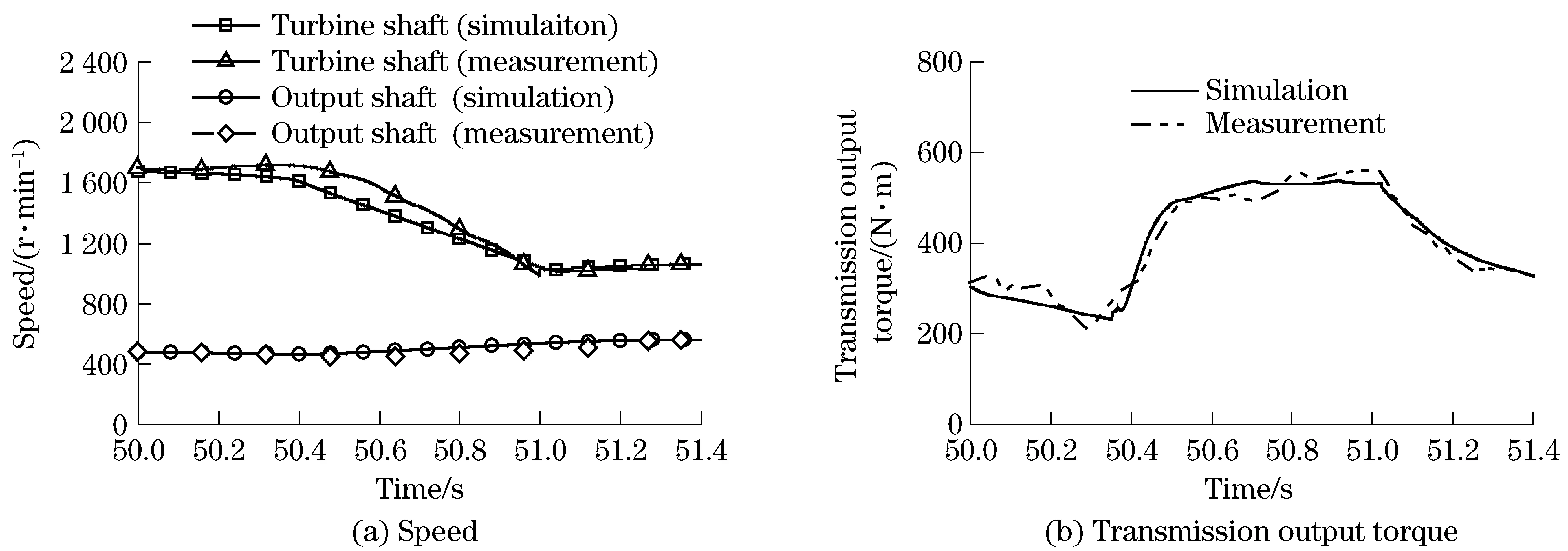
Fig.4 Comparison of simulations and measurements, TL=1 500 N·m
2 Optimal tracking control for shift process
In order to minimize the shift jerk and friction loss, an optimal tracking control algorithm is developed for the inertia phase during the shift process. The control strategy during the torque phase still uses the open-loop control of clutch pressure.
2.1 State space representation
It should be noted that the clutch C4 slips during the inertia phase, while the clutch C5 is supposed to be disengaged andTC5is set to zero[11]. Therefore, the dynamic equations of planetary gearbox can be written as
(24)
According to Eqs. (16) (20) (22)-(24), the equations of motion of the gearbox during the inertia phase can be concluded as
(25)
The dynamics of the 1-2 shift process can be described byωtandωo. Then the state vector is defined as
(26)
Introducing the control vector consisting of the turbine torque TtandthefrictiontorqueofclutchC4 TC4
(27)
Theequationsofmotionofthepowertrainmodelcanbeformulatedas
(28)
(29)
Therefore,thefollowingstatespaceequationcanbeobtained
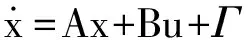
(30)
In order to eliminate theinfluence of disturbanceΓ, assuming that
(31)
(32)
uo=-B-1Γ
(33)
then the system can be written as
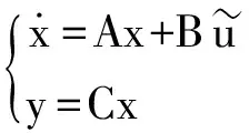
(34)

2.2 Problem formulation
The shift jerk is a general index for evaluating the shift comfort. The shift jerk is defined as the derivative of the longitudinal acceleration with respect to time.
(35)
where jistheshiftjerk; aisthelongitudinalacceleration.
Eq.(35)showsthattheshiftjerkcanbeminimizedaslongasthevalueofωois fixed or variable in a fixed rate. In this paper, the tracking trajectory of the output shaft angular velocityz1is set as
(36)
whereωo0is the initial value of the output speed in the inertia phase;aois the desired vehicle acceleration.
The friction loss is defined as the work done by the relative slip of the driving and driven friction plates during clutch engaging process.
(37)
where WC4isthefrictionlossofclutchC4.
Thetrackingtrajectoryoftheoutputshaftangularvelocityhasbeendetermined.Therefore,thecontrolproblemtominimizethefrictionlosscanbetransformedintoaturbinespeedtrackingcontrolproblem.Alargenumberofresearchesshowthatafeedbackcontroloftheturbinespeedcansignificantlyimprovetheshiftquality.Generally,thedesiredturbinespeedissettovaryinafixedrate[10].Thereby,thetrackingtrajectoryoftheturbinespeedangularvelocityz2issetas
z2(t)=ωt0-αt0t
(38)
whereωt0is the initial value of the turbine speed in the inertia phase;αt0is the desired turbine angular acceleration.
The expected output z(t) is defined as
(39)
In the paper, the control objection of the optimal tracking control is to ensure that y(t) can accurately track z(t) with the minimal control energy consumption. The performance index of the optimal tracking control during the shift process is formulated as
(40)
where Q and R are the weight matrices.
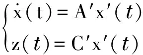
The shift quality control problem has been transformed to a linear quadratic optimal tracking control problem, that is
(41)
2.3 Optimal tracking control law
The linear quadratic optimal tracking control problem is solved by the Pontryagin’s minimum principle[12]. The optimal control law is obtained
(42)
P(t) satisfies the matrix differential Riccati equation
(43)

In the paper, an integrated powertrain control is proposed to achieve the optimal control law. The engine is controlled by the turbine torque closed loop control based on the PID algorithm. Meanwhile, the transmission is controlled by the clutch pressure open loop control according to Eqs.(17)(19).
3 Results
In the following, some results achieved by applying the proposed optimal tracking control law to the verified powertrain simulation model are presented. The reference control is the same one used to verify the simulation model.
Fig.5 shows the shift jerk and friction loss in the case that the load torque is 750 N·m. With the reference control, the maximum positive jerk is 28 m/s3and the maximum negative jerk is -14 m/s3. Additionally, the friction loss is 4 300 J. As expected, by applying the optimal tracking control, the maximum positive jerk and negative jerk are reduced to 23 m/s3and -8 m/s3, respectively. Furthermore, the friction loss is reduced to 3 300 J.
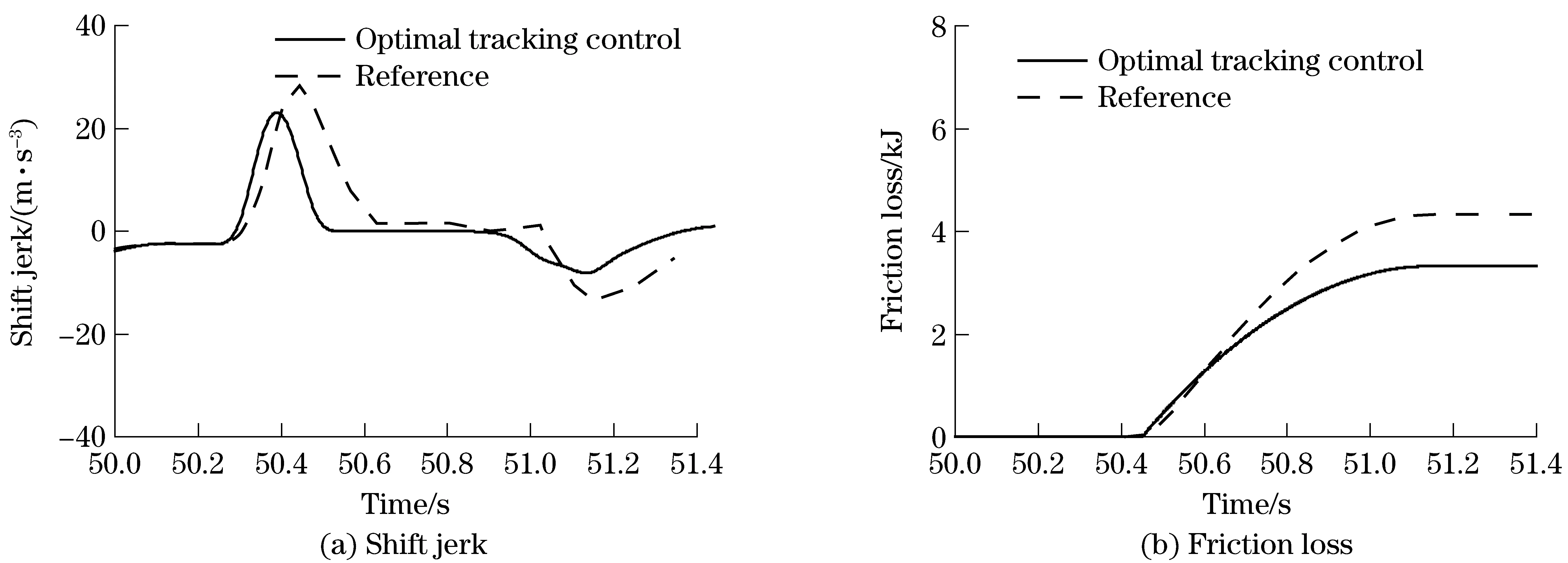
Fig.5 Results of TL=750 N·m
Fig.6 shows the results for the case that the load torque is 1 500 N·m. By the application of the reference control, the maximum positive jerk is 25 m/s3and the maximum negative jerk is -12 m/s3. Additionally, the friction loss is 6400J. While, applying the optimal tracking control algorithm, the maximum positive jerk and negative jerk are only 15 m/s3and -9 m/s3, which apparently improve the shifting comfort. Furthermore, the friction loss is reduced to 5 300 J, which improves the life expectancy of the friction discs.
The results demonstrate that the shift jerk and friction loss can be significantly reduced by applying the proposed optimal tracking control algorithm. Moreover, the proposed control approach is found to be robust under different load cases.
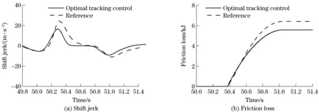
Fig.6 Results of TL=1 500 N·m
4 Conclusions
An optimal tracking control algorithm of the shift process for the vehicle with automatic transmissions was proposed in this paper. Based on the dynamic analysis of the shift process using the Lagrange method, a mechanical model of the powertrain system is developed and verified. Considering the shift jerk and friction loss during the shift process, the turbine speed and output shaft speed tracking trajectories are defined. Then the shift quality control problem has been transformed to a linear quadratic optimal tracking control problem. The problem has been solved by the Pontryagin’s minimum principle.
The optimal control law of the shift process derived in this paper consists of both a feedforward and a feedback portion. The feedforward control is to match the load torque. Meanwhile, the feedback control is to ensure that the system can accurately track the target trajectories.
The simulation study of the 1-2 upshift process under different load conditionsis carried out based on the verified powertrain model. The simulation results show that the shift jerk and friction loss can be significantly reduced by application of the proposed optimal tracking control.
[1] Sun Z, Hebbale K. Challenges and opportunities in automotive transmission control[C]// Proceedings of the 2005 American Control Conference, Portland, Oregon, USA, 2005: 3284-3289.
[2] Greiner J, Grumbach M. Automatic transmission systems beyond 2020: challenges and competition[C]// SAE 2013 World Congress & Exhibition, Detroit, Michigan, USA, 2013: 2013-01-1273.
[3] Cho D. Nonlinear control method for automotive powertrain system[D]. Massachusetts: Massachusetts Institute of Technology, 1987.
[4] Hebbale K, Kao C. Adaptive control of shifts in automatic transmissions[C]// Proceedings of the 1995 ASME International Mechanical Engineering Congress and Exposition, San Francisco, California, USA, 1995: 171-182.
[5] Minowa T, Ochi T, Kuroiwa H, et al. Smooth gear shift control technology for clutch-to-clutch shifting[C]// International Congress and Exposition, Detroit, Michigan, USA, 1999: 1999-01-1051.
[6] Haj-Fraj A, Pfeiffer F. Optimal control of gear shift operations in automatic transmissions[J]. Journal of the Franklin Institute, 2001, 338(2-3): 371-390.
[7] Hahn J O, Hur J W, Choi G W, et al. Self- learning approach to automatic transmission shift control in a commercial construction vehicle during the inertia phase[J]. Proceeding of the Institution of Mechanical Engineers, Part D: Journal of Automobile Engineering, 2002, 216(11): 909-919.
[8] Watechagit S, Srinivasan K. Implementation of on-line clutch pressure estimation for stepped automatic transmission[C]// Proceedings of the 2005 American Control Conference, Portland, Oregon, USA, 2005: 1607-1612.
[9] Song X, Sun Z. Pressure-based clutch control for automotive transmission using a sliding-mode controller[J]. Transactions of the IEEE/ASME on Mechatronics, 2012, 17(3): 534-546.
[10] Gao B, Chen H, Tian L, et al. A nonlinear clutch pressure observer for automatic transmission: considering drive-shaft compliance[J]. Transactions of the ASME, Journal of Dynamics Systems, Measurement, and Control, 2012, 134(1): 11-18.
[11] Tokura T, Asami T, Hasegawa Y, et al. Development of smooth up-shift control technology for automatic transmissions with integrated control of engine and automatic transmission[C]// SAE World Congress & Exhibition, Detroit, Michigan, USA, 2007: 2007-01-1310.
[12] Naidu D S. Optimal control systems[M]. Boca Raton, FL: CRC Press, 2002: 125-141.
(Edited by Wang Yuxia)
10.15918/j.jbit1004-0579.201524.0405
U 27 Document code: A Article ID: 1004- 0579(2015)04- 0458- 08
Received 2014-10- 31
Supported by the National Natural Science Foundation of China(51475043)
E-mail: hy111@bit.edu.cn
猜你喜欢
环境卫生工程(2021年1期)2021-03-19
装备制造技术(2020年1期)2020-12-25
青年歌声(2019年12期)2019-12-17
疯狂英语·初中天地(2019年2期)2019-07-28
农家书屋(2017年11期)2017-12-16
歌剧(2017年4期)2017-05-17
锻压装备与制造技术(2016年3期)2016-06-05
海峡姐妹(2016年7期)2016-02-27
城市轨道交通研究(2015年3期)2015-02-27
音乐周刊(2011年1期)2011-08-16
 Journal of Beijing Institute of Technology2015年4期
- Journal of Beijing Institute of Technology的其它文章
- Influence of shear sensitivities of steel projectiles on their ballistic performances
- Triaxial high-g accelerometer of microelectro mechanical systems
- Dynamic modeling and simulation for the rigid flexible coupling system with a non-tip mass
- Multi-constrained model predictive control for autonomous ground vehicle trajectory tracking
- Estimating the clutch transmitting torque during HEV mode-switch based on the Kalman filter
- High-precision method of detecting motion straightness based on plane mirror interference