
Experimental study on compression stroke characteristics of free-piston engine generator
2015-04-22 07:24ZUOZhengxing左正兴XUDatao许大涛FENGHuihua冯慧华
ZUO Zheng-xing(左正兴), XU Da-tao(许大涛), FENG Hui-hua(冯慧华)
(School of Mechanical Engineering, Beijing Institute of Technology, Beijing 100081, China)
Experimental study on compression stroke characteristics of free-piston engine generator
ZUO Zheng-xing(左正兴), XU Da-tao(许大涛), FENG Hui-hua(冯慧华)
(School of Mechanical Engineering, Beijing Institute of Technology, Beijing 100081, China)
The compression stroke characteristics of free-piston engine generator were studied. The numerical model of the compression stroke was established based on thermodynamics and dynamics equation, and the leak loss, heat loss and friction loss were considered. Through solving numerical equations, the in-cylinder pressure of compression stroke under different compression ratios was calculated, energy transfer and conversion process was analyzed, and the calculated results were experimentally verified. The results showed that the actual effective output of electronic energy and the compression energy stored in the compressed gas accounted for about 70%. The compression energy gradually increased with the increasing compression ratio. When the compression ratio was more than 7.5, the actual compression energy increased slowly and the energy error between simulation and test decreased.
free-piston engine generator; compression stroke; experimental study; energy conversion
A free-piston engine generator is a novel power mechanism, which is a combination of the piston of free piston engine and the mover of linear generator. It does not have a connecting rod as in a traditional engine, which can make the kinetic energy of piston’s linear motion output to the external load conversion device directly, so it has a broad application prospect in the electric field[1]. Moreover, it has many advantages such as compact structure, high power density, wide fuel types and emissions of good quality. Therefore, it has gradually become the focus of research in recent years[2-7].
The cylinder gas organization of a free-piston engine generator is significant different from a crankshaft engine because of its special piston motion. A free-piston engine generator can freely adjust the engine working stroke, which directly affects the combustion process and performance[6]. In the thermodynamic cycle of cylinder gas, the compression stroke is one of the key factors influencing the startup, the subsequent working process and the combustion.
Based on a developed free-piton engine generator and considering the leak loss, heat loss and friction loss, we established a mathematical model of compression stroke. The compression stroke under different compression ratios conditions was analyzed. The simulation results and experimental results were compared, and the changing characteristics of the in-cylinder pressure and compression energy were analyzed. Make sure the influencing factors of the whole process so as to obtain a more accurate model of compression stroke, it is essential for in-depth research on the performance and the establishment of stable control strategy of free-piston engine generator, and it can provide reference in order to improve the startup process of engine.
1 Structure characteristic of free-piston engine generator
The load device of a free-piston engine generator is the linear generator connected with the generator mover and the free piston. The kinetic energy of piston obtained from the fuel combustion is directly converted into electrical energy by electromagnetic energy conversation. The object in this research is a two stroke dual-piston opposed-type free piston engine generator. The structure is shown in Fig.1. Two pistons and the mover of a linear generator are rigidly attached to constitute a piston assembly though a connecting rod.
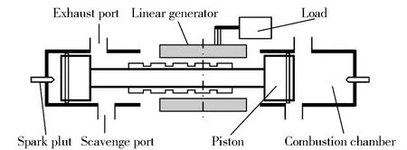
Fig.1 Free-piston engine generator configuration
When the free-piston engine generator is starting, the motor drives the mover and the free piston to move in order to achieve the fundamental conditions of mixture combustion. Mixed gas is provided by the fuel system and enters the cylinder though the inlet. When the piston is closed to the top dead center of one side, compression stroke is about to the end, the control system implements the spark plug ignited, and the combustion of this side cylinder is realized. Meanwhile, the motor is converted into generator mode. Then, the gas explosion pressure promotes the piston backward movement to conduct the working process. The other side cylinder is turned into the scavenging and subsequent compression stroke, and the piston is pushed back after the cylinder combustion. Thus, both sides of the cylinder are ignited alternately; free piston can move continuously between the two dead centers, and the continuous inductive power can be obtained to achieve energy conversion. However, the strong coupling characteristics of both sides cylinder have also brought difficult problems on stable control of combustion. So compression stroke characteristics before the burning is essential for combustion stability.
2 Analysis of compression stroke
2.1 Dynamic modeling
The compression stroke of a free-piston engine generator refers to the free piston moving from one side to the other side of the top dead center of the cylinder. In this process, the free piston is commonly affected by the cylinder gas pressure, the electromagnetic force, the friction force and the gas pressure of the scavenging box, as shown in Fig.2. Assuming that the gas pressures of both sides of the scavenging box are equal, they are offset mutually. Therefore, the movement process of free piston can be expressed as
(1)
wheremis the mass of the moving parts, including free piston mass, motor mover mass and connecting rod mass;xis the displacement of the piston assembly;PL,PRare the pressures in the left and right cylinders;Ais the top area of the piston;Ffis the friction force;Feis the electromagnetic force introduced by the linear generator.
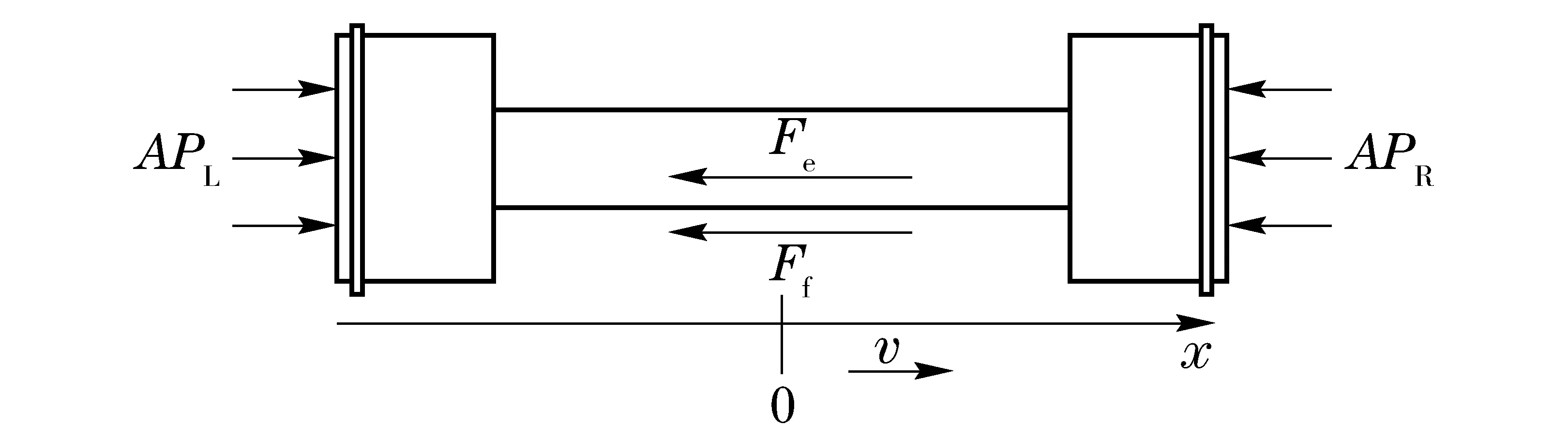
Fig.2 Free body diagram of free-piston engine generator
2.2 Compression energy modeling
Compression energy refers to overcoming the cylinder gas pressure and store energy in the startup process of the first stroke, when the exhaust port is closed by the free piston until it moving to the top dead center.
In the actual working process of free piston engine generator, due to the leak loss, the cylinder thermodynamic process is a mass transfer process.In the compression stroke, applying the law of mass conservation for the cylinder gas
(2)
wheremVis the gas mass of combustion chamber;mLis the mass of leak loss. According to the energy conservation equation, the energy changing of cylinder gas can be expressed as
(3)
whereECis the total energy of in-cylinder gas;Qis the outflow or inflow energy of in-cylinder gas;Wis the output work;his the enthalpy flow. In addition, due to the gas work dW=PdV, andEC=mLu, after the differential we have
(4)
Combinedwiththedifferentialexpressionoftheidealgasstateequation
(5)
Accordingtothethermodynamicrelation:R=cP-cV, γ=cP/cVandu=cVT,weyield
(6)
whereP,Vare the gas pressure and volume of combustion chamber;cP,cVare the constant pressure specific heat and constant volume specific heat;uis the internal energy;Ris the gas constant;Tis the gas temperature of in-cylinder gas.
During the time of free piston moving from the upper edge position of the exhaust port to the top dead center, the thermodynamic changing of combustion chamber is expressed as the effective compression process. In this case, the gas energy increment of combustion chamber is
(7)
wherexLgis the position of top dead center;xLeis the upper edge position of exhaust port.
2.3 Friction energy modeling
The friction force of free piston mainly comes from the piston ring and the piston skirt portion. Also, there is friction force at the piston pin, but the force is small compared to the other parts. According to the simplified empirical formula of the piston ring pack friction force[2], the friction force can be represented by
(8)
wherepfmep=AmSn,Am=150 kg·m-2·s-1,Bis the bore of the cylinder,Sis the maximum stroke length,pfmepis the mean effective friction force,nis the frequency of reciprocation of the piston assembly. The friction energy loss of a compression stroke is
(9)
2.4Lineargeneratorenergymodeling
Theelectromagneticforceofalineargeneratorisproportionaltothesimplifiedvelocity[5].Assumingthattheelectromagneticforceconstantisc, we can have
(10)
Withoutconsideringtheloadenergylossandotherlosses,thegeneratoroutputpowercanbeconsideredastheoutputenergyofthesystem,whichisequaltotheworkdonebytheelectromagneticforceinonecycle.Thegeneratoroutputenergycanbeexpressedas
(11)
2.5Heatlossenergymodeling
Theenergylosscausedbytheheatexchangeamongtheinternalwallsurfaceofcombustionchamberhasagreatimpactonthermalefficiencyforfree-pistonenginegenerator,whichisanimportantphenomenonoccurredintheenginecombustionsystem.Thoughtheengineheatbalanceexperiment,wecanfindthatabout1/3thereleasedheatfromfuelcombustioniswastedthoughheattransfer[8].However,theemittedheatatdifferenttimesinanengineworkingcycleisnotallaffectingtheheatefficiency.Whenthepistonisnearthetopdeadcenterofcompressionstroke,theworkcapacityofcylindergasisreduceddirectlybytheheatlossthatthegastowardstothewallsurface.Therefore,ithasagreatimpactonthethermalefficiency.In-cylinderheattransferismodeledaccordingtoHohenberg[9]:
(12)
(13)
wherehhis the heat transfer coefficient,Acylis the in-cylinder surface area in contact with the gas,Twis the average temperature of the in-cylinder surface face,VAis the mean piston velocity. The heat loss energy of a compression stroke is
(14)
2.6Leaklossenergymodeling
Asthereisagapbetweenthefreepistonandthein-cylinderwallsurfaceinthefree-pistonenginegenerator,thein-cylindermixturewillinevitablyincurleakagephenomenon.Theleakageofenginecanbeconsideredasone-dimensionalsteadyflow,thegapareacanbetreatedasagradualretractablenozzle.Accordingtothecontinuityequation,themassflowthatthegasgoesthougharbitrarycross-sectionissame.Leakmassflowrateiscalculatedas[10]
(15)
whereAtis the gap area between the piston and cylinder,Rmis the mixed gas constant,y(Po,Pe,γ)istheflowfunction, Peistheoutsidepressure.Whenthein-cylinderpressureishigher,theflowpresentsasupercriticalstate,thein-cylindergasflowsthoughthegapatthelocalsoundspeed,theleakflowonlydependsonthein-cylindergasstateandthesizeofgaparea,andithasnothingtodowithoutsidegasstate.Theleakflowfunctioncanbeexpressedas
y(Po,Pe,γ)=
(16)
Thus, the leak loss energy of a compression stroke can be described as
(17)
3 Simulation and experimental studies
3.1 Experimental prototype
The basic structure parameters of a free-piston engine generator are determined by the principle of prototype design and selection, as listed in Tab.1. In the simulation model, the compression polytropic coefficientmcis taken as 1.30[2].
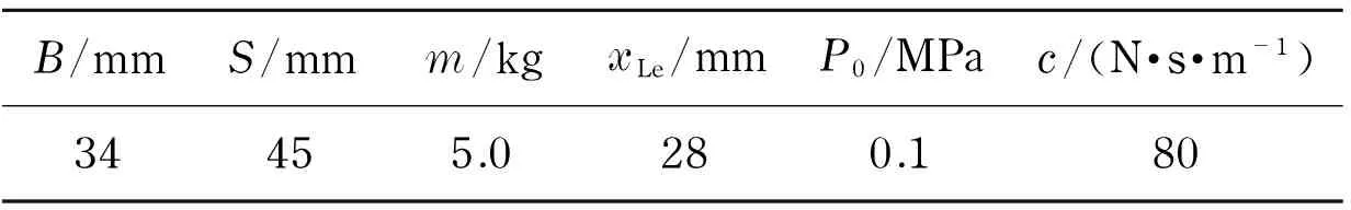
Tab.1 Specifications of a free-piston engine generator
Based on the test platform of the free-piston engine generator, a group of motor was added to this system and the controllable motor reciprocation was utilized for the system test. The test prototype was shown in Fig.3. It consisted of the engine subsystem, the linear motor subsystem and the control and test subsystem. The test equipments were as follows: the engine cylinder and cylinder head were selected from a two-stroke model aircraft engine, the cylinder body and connecting rod were designed independently, and the linear motor was selected from a commercial flat motor. The displacement of piston assembly was collected by a grating displacement sensor. The in-cylinder pressure was collected by a Kistler gas pressure sensor, and the measured pressure was relative values. Compared with the collected displacement and pressure, the changes of in-cylinder pressure of compression stroke were obtained.
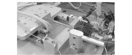
Fig.3 Prototype of free-piston engine generator
According to the fundamental characteristics of compression stroke, the system simulation model was established with Matlab/Simulink, and simulation and experimental research were conducted.
3.2 Experimental results
The simulation and experimental results of in-cylinder gas pressure of compression stroke under different compression ratios are shown in Fig.4. It can be found that there is a gap between the simulation and experimental curves. In the first half of the compression stroke, the two curves are very close when the in-cylinder pressure is smaller. With the deepening of compression stroke, the in-cylinder pressure gradually increases, and the simulated pressure increases faster than the experimental measurements. As shown in Fig.5a, the in-cylinder peak pressure of simulation is greater at the same compression ratio. If the compression ratio is bigger, the value error between simulation and experiment becomes bigger. The reason is that due to the smaller cylinder bore of the prototype, one piston ring is used to seal between the piston and the cylinder, so a certain amount of leak area is existed in it. Effective seal measures can’t be done, therefore, it becomes the main source of the leak. The leak is more significant if the pressure of in-cylinder gas is bigger.
Fig.4 Changes of in-cylinder gas pressure of compression stroke in different compression ratios

Fig.5 Peak pressure and compression energy in different compression ratios
Fig.6 Compression energy error and error ratio
The compression energy is obtained by numerical integration of the cylinder pressure.The compression energy under different compression ratios is shown in Fig.5b. With increasing compression ratio, the compression energy gradually increased. The differences between simulation and experiment are that, when the compression ratio is more than 7.5, the increasing rate of compression energy becomes slow with increasing compression ratio, which is similar to the changes in the experimental results of peak pressure. The compression energy from experiments is quite different from the theoretical values. Fig.6 shows the error of experimental and simulation values. It can be seen that the compression energy error gradually decreases as the compression ratio increases, and the energy error ratio also gradually decreased. The main reason is that higher compression ratio results in greater leak energy loss, but the increasing rate is less than the increasing rate of compression energy. Meanwhile, the peak pressure increased as the compression ratio increases, and the friction force between the piston ring and the cylinder also increases, causing a greater friction energy loss. Further, the bigger the compression, the higher the temperature. The heat transfer energy loss will cause a certain amount of energy loss.
3.3 Energy conversion process
The energy conversion process of a free-piston engine generator refers to the process of the electrical energy of motor converting to the internal energy of gas at the same with the output of electrical energy. According to the above analysis, considering the leak energy loss, heat energy loss and friction energy loss in the whole compression stroke, the total energy can be calcualted as
∑E=Ep+Ef+Ee+EL+Qh
(18)
Based on the design parameters of free-piston engine generator,the necessary energy and its distribution relationship can be obtained by using numerical integration methods, as shown in Fig.7. From Fig.7, the compression energy of gas and output energy of generator occupy the main parts in the compression stroke; about 42% energy is as the generator output; the leak loss and heat loss are larger and the friction loss is smaller. More energy should be used to increase the internal energy of gas by appropriately reducing the output of the electrical energy so as to improve the startup performance of the engine.
Fig.7 Energy conversion distribution of compression stroke
4 Conclusions
① Due to the leakage between the piston ring and the cylinder and the heat of the cylinder wall, there are differences between experiment and simulation of in-cylinder gas pressure in the actual compression stroke. The peak pressure and compression energy of experiment are generally lower than the theoretical.
② Compression stroke is the process of the motor electrical energy converting to the gas internal energy. The input energy of compression stroke is mainly from the motor electrical energy, and absorbed by the gas internal energy and output electrical energy of generator. The compression energy gradually increased with increasing compression ratio. The compression energy increasing rate becomes slow when the compression ratio is more than 7.5. The compression energy error gradually decreased and so is the energy error.
③ In the energy conversion process of compression stroke,the gas compression energy and output of generator accounts for the main parts, about 42% energy is as the output of electrical energy. Leak loss and heat loss are larger than friction loss. More energy should be used to increase the internal energy of gas by appropriately reducing the output of the electrical energy so as to improve the startup performance of the engine.
[1] Mikalsen R, Roskilly A P. A review of free-piston engine history and applications [J]. Applied Thermal Engineering, 2007, 27(14-15): 2339-2352.
[2] Atkinson C M, Petreanu S, Clark N N, et al. Numerical simulation of a two-stroke linear engine-alternator combination, SAE paper, 01-0921 [R]. Warrendale, PA, USA: Society of Automotive Engineers, 1999.
[3] Mikalsen R, Roskilly A P. Performance simulation of a spark ignited free-piston engine generator [J]. Applied Thermal Engineering, 2008, 28(14-15): 1726-1733.
[4] Li Qingfeng, Xiao Jin, Huang Zhen. Simulation of a two-stroke free-piston engine for electrical power generation [J]. Energy & Fuels, 2008, 22(5): 3443-3449.
[5] Xu Zhaoping, Chang Siqin. Prototype testing and analysis of a novel internal combustion linear generator integrated power system [J]. Applied Energy, 2010, 87(4): 1342-1348.
[6] Mao Jinlong, Zuo Zhengxing, Li Wen, et al. Multi-dimensional scavenging analysis of a free-piston linear alternator based on numerical simulation [J]. Applied Energy, 2011, 88(4): 1140-1152.
[7] Tian Chunlai, Feng Huihua, Shang Jiao, et al. Energy conversion and transfer process of free-piston engine generator [J]. Transactions of the Chinese Society for Agricultural Machinery, 2012, 43(11): 11-14. (in Chinese)
[8] Yang Jialin. Gasoline engine combustion system development [M]. Beijing: China Machine Press, 2009.(in Chinese)
[9] Mao Jinlong, Zuo Zhengxing, Liu Dong. Numerical simulation of a spark ignited two-stroke free-piston engine generator [J]. Journal of Beijing Institute of Technology, 2009, 18(3): 283-287.
[10] Wang Baoguo, Liu Shuyan, Huang Weiguang. Gas dynamics [M]. Beijing: Beijing Institute of Technology Press, 2005. (in Chinese)
(Edited by Cai Jianying)
DOI: 10.15918/j.jbit1004-0579.201524.0306
TK 441 Document code: A Article ID: 1004- 0579(2015)03- 0321- 07
Received 2013- 12- 27
Supported by the National Natural Science Foundation of China (51006010); the Program of Introducing Talents of Discipline to Universities (B12022)
E-mail: xudatao2010@163.com
 Journal of Beijing Institute of Technology2015年3期
- Journal of Beijing Institute of Technology的其它文章
- High-rise building fire pre-warning model based on the support vector regression
- Dynamic modeling and simulation for the flexible spacecraft with dynamic stiffening
- Experimental study on the time-dependent dynamic mechanical behaviour of C60 concrete under high-temperatures
- Numerical simulation and optimization of the cylinder head water jacket based on the two-phase flow boiling heat transfer
- Multi-action-based approach for constructing knowledge map
- Slow driving control of tracked vehicles with automated mechanical transmission based on fuzzy logic