
Novel miniature pneumatic pressure regulator for hopping robots
2015-04-24 05:30SAMOSaifullahMAShuyuan马树元SAMEHBdran
SAMO Saifullah, MA Shu-yuan(马树元), SAMEH Bdran
(School of Mechanical Engineering,Beijing Institute of Technology,Beijing 100081, China)
Novel miniature pneumatic pressure regulator for hopping robots
SAMO Saifullah, MA Shu-yuan(马树元), SAMEH Bdran
(School of Mechanical Engineering,Beijing Institute of Technology,Beijing 100081, China)
A novel miniature pressure regulator is fabricated and studied. The regulator can easily be integrated into portable mechatronics or miniature robotic applications because of its lightweight and compact size. An especial poppet is designed to minimize its size and to withstand high-pressure. The pressure regulator is designed for a hopping robot which is powered by a combustion system. The hopping robot has great moving capacities such as jumping over big obstacles, walls and ditches. The regulator helps the hopping robot to decrease size and weight, and to sustain high pressure of oxygen and fuel tank. It will maintain constant output pressure to obtain suitable proportion of oxygen and fuel in the combustion cylinder. Dynamic simulation of the miniature pneumatic pressure regulator is performed. Experiments on prototype of miniature pneumatic pressure regulator are also carried out to validate the performance and satisfied performance is obtained.
hopping robot; poppet valve; pneumatic pressure regulator; pressure control
Miniature pneumatic pressure regulators are widely used in small and portable devices where space and weight is limited. The main applications of a miniature pressure regulator are miniature electromechanical devices, medical instruments, pneumatic muscles, rehabilitation facilities, etc. In artificial pneumatic muscles, thousands newtons of forces can be generated with pressure of 0.3-0.5 MPa[1]. Conventionally, most robots are actuated by motors with gears and battery, which have a heavy drive system and low power density. Pneumatic actuators with high pressure can substitute for conventional drive system with motors because of its lightweight and high power. In these cases, high pressure air should be supplied, but normal miniature pneumatic regulators cannot offer high pressure operation. The high pressure pneumatic actuators are required where high power and lightweight structures are critical[2].
Many researches are focused on gas pressure regulators to characterize their behaviors and the effects of environment, operating conditions and installation on the permanence of pressure regulator[3]. Methodology was developed to investigate the stability of pressure regulator[4-5]. The poppet valves that pass on the flow of gas after motivation[6- 7]were also studied. Poppet valves are available for long time but have a short lifetime. Poppet valves are now increasingly used for various applications[8-10]. In this study, a lightweight miniature pneumatic pressure regulator is designed with a poppet valve and a prototype is fabricated for small portable devices.
The robot hop control system (Fig.1) in an early study uses a small combustion engine in which gas tanks are stationary and engine is orientation-variable inside robot body during operation. Gas tank is filled with high pressure (more than 4 MPa) gas to maximize hopping performance of robot. High pressure can maximize jumping times with a limited capacity of tank. As the engine is a moving part, it cannot be connected to gas tank with rigid pipes. Therefore, gas tank is connected to engine with a soft air hose (2 mm diameter). The flexible air hose can sustain 0.8 MPa. However, the gas tank contain more than 4 MPa pressure. So it is difficult for the air hose to hold such high pressure. A pressure regulator can be used to sustain inlet high-pressure and give suitable output pressure for air hose. It is necessary that the pressure regulator does not add much weight and increase the volume of robot body. It also should control outlet pressure efficiently. Therefore, a new miniature pressure regulator with high pressure supply is developed in the research to complete the portable robotic application.

Fig.1 Hop control system of a hopping robot
Fig.1a is the hopping robot where the developed miniature pneumatic pressure regulators are installed. The pneumatic control system is shown in Fig.1b. The system consists of two miniature pneumatic pressure regulators, two check valves, three on/off type solenoid valves, an ignition coil, a cylinder hollow piston assembly, a miniature pressure sensor and a microcontroller.
The on/off type solenoid valves are used to allow or cutoff the flow of oxidant and fuel. A miniature pressure sensor monitors pressure inside the combustion chamber and sends information to the microcontroller that controls on/off solenoid valves to maintain desire pressure inside combustion chamber. The oxidant and fuel are drawn into combustion chamber respectively through check valves and ignites. After igniting the fuel & oxidant mixture, the stored chemical potential energy is released. The chemical potential energy is changed into kinetic energy, causing the piston to move down. The piston pushes the ground and in reaction hopping robot goes up into air. Check valves are used to prevent flow to return and minimize the deflagration and detonation effects on miniature pressure regulators.
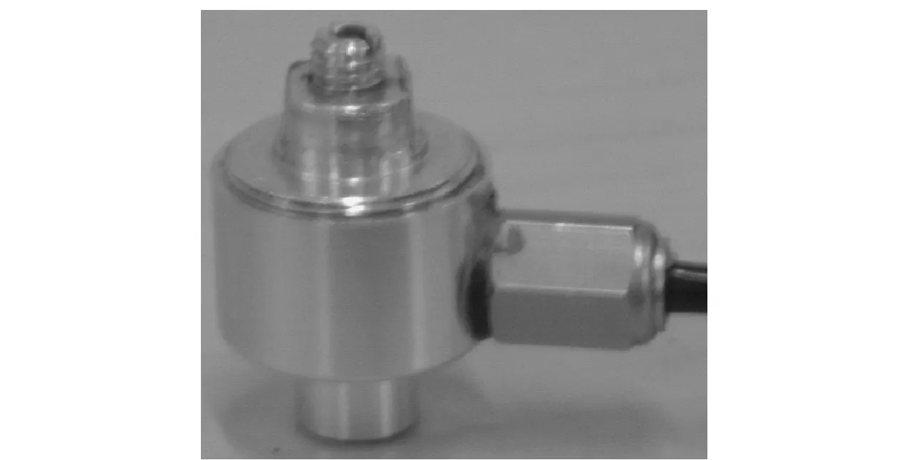
Fig.2 Miniature pressure regulator
The developed miniature pressure regulator (Fig.2) is made of aluminum with 15 g weight, 32 mm height, and 22 mm width. The constant pressure can easily be obtained from developed miniature pressure regulator regardless of the variation in inlet pressure. The integration of miniature pressure regulator in any mechatronics/robotics applications is uncomplicated with the help of a step motor, where variable pressure is required. The knob of the miniature pressure regulator can be adjusted by the step motor to get desired and maintain constant output pressure.
1 Working principle of the miniature pressure regulator

Fig.3 Schematic of miniature pressure regulator
Fig.3 shows the schematic of the miniature pneumatic pressure regulator. The regulator consists of a poppet valve and diaphragm. The poppet is loaded by a small spring and a pressure spring. The small spring with stiffnessknsis pre-compressed and not adjustable. The pressure spring with stiffnesskpsis pre-compressed by a distancexs. An adjuster knob can adjust compression of the pressure spring. The spring forces and pressure forces govern the motion of diaphragm and poppet. The poppet displacement under both (opened and closed) conditions is limited mechanically. Pre-compressed force of the pressure spring pushes the poppet against the small spring and allows the gas to enter the low-pressure chamber. After gas enters the low-pressure chamber, the chamber pressure increase and acts on the diaphragm. When the pressure force in the low-pressure chamber exceeds the pressure spring force, the diaphragm will concave to press the pressure spring and the poppet displaces towards seat. Poppet closes the path from the inlet port to the outlet port to cuts off the gas flow and prevents any more gas from entering the regulator, if the low-pressure chamber pressure is over the pre-adjusted value.
2 Miniature pressure regulator design
The developed miniature pressure regulator is featured with lightweight and compact size as shown in Fig.1. The design of miniature pressure regulator is simple and easy to fabricate. The parts of miniature pressure regulator are shown in Fig.4. The main components of miniature pressure regulator are a poppet and a diaphragm. The diaphragm is sensitive to pressure. Therefore, the device has high sensitivity and can respond quickly. It is necessary for the pressure regulator to guide the required motion of the poppet for high flow, fast acting and also preventing side motions. The poppet of pressure regulator should be in center for instant action of closing or openings and for improved functionality. A small poppet is designed to reduce the volume of pressure regulator. An especial design of poppet shown in Fig.5 has the ability to withstand high inlet pressure and minimize side motions. The poppet is like a gate between high-pressure and low-pressure chambers. It is designed in a manner that it can easily & rapidly engage the seat to cut-off the gas flow and depart the seat to allow the gas flow without making any extra movement.
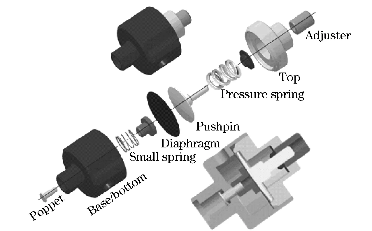
Fig.4 Parts of miniature pressure regulator and their assembly
The diaphragm combined with pressure spring is working as sensing element. It is more sensitive to pressure changes and reacts more quickly. Rubber diaphragm is used in one piece to maintain its strength. The diaphragm is thinnest and weakest part of the miniature pressure regulator and is installed between atmosphere pressure chamber and low-pressure chamber. It is supported by a pushpin to prevent damages. Diaphragm covers the low pressure chamber and diaphragm material acts as a seal to contain the pressure in low pressure chamber while the pushpin gives enough strength to diaphragm to withstand the pressure. The small spring is located in the low-pressure chamber to keep the poppet at initial position. The pressure spring is located in atmosphere pressure chamber to push the poppet for opening gas flow. The small spring and pressure spring provide loading forces in opposite directions. The force generated by pressure acted upon the diaphragm will compress the pressure spring and de-compress the small spring to deform the diaphragm then change the gas flow.
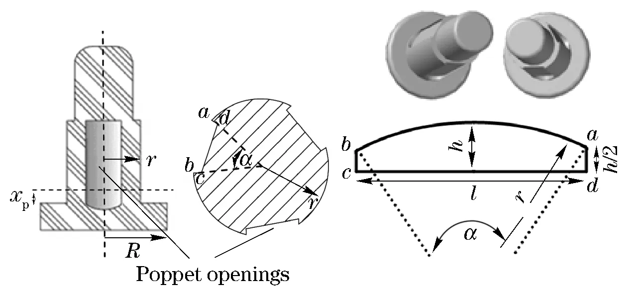
Fig.5 Poppet geometry and poppet openings
3 Mathematical modeling
The dynamic behavior of the miniature pressure regulator is described by the following set of mathematical relations.
3.1 Poppet valve throttling area
The poppet is placed in a guided hole at distancexpfrom the closing position. The gas flow is allowed to enter the low-pressure chamber through the opening area. The opening area consists of three slots as shown in Fig.5. The area of each slot isAswhich is maximum opening for flow of gas. The throttle areaAtdepends on the poppet displacementxp. In the following mathematical expressions,ris the radius of shaft andαis the angle of opening cut. One of the opening areaAsis
(1)
The circumferenceCis the summation ofLabarc length andLbc,LcdandLdaline segment lengths.
Lab=αrh/2=Lbc=Lad=r(1-cos(α/2))
l=Lcd=2rsin(α/2)
C=Lab+Lbc+Lcd+Lda=r[α+2(1-cos(α/2))+2sin(α/2)]
(2)
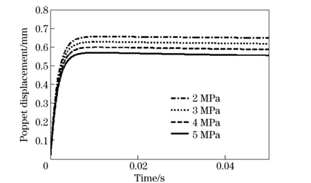
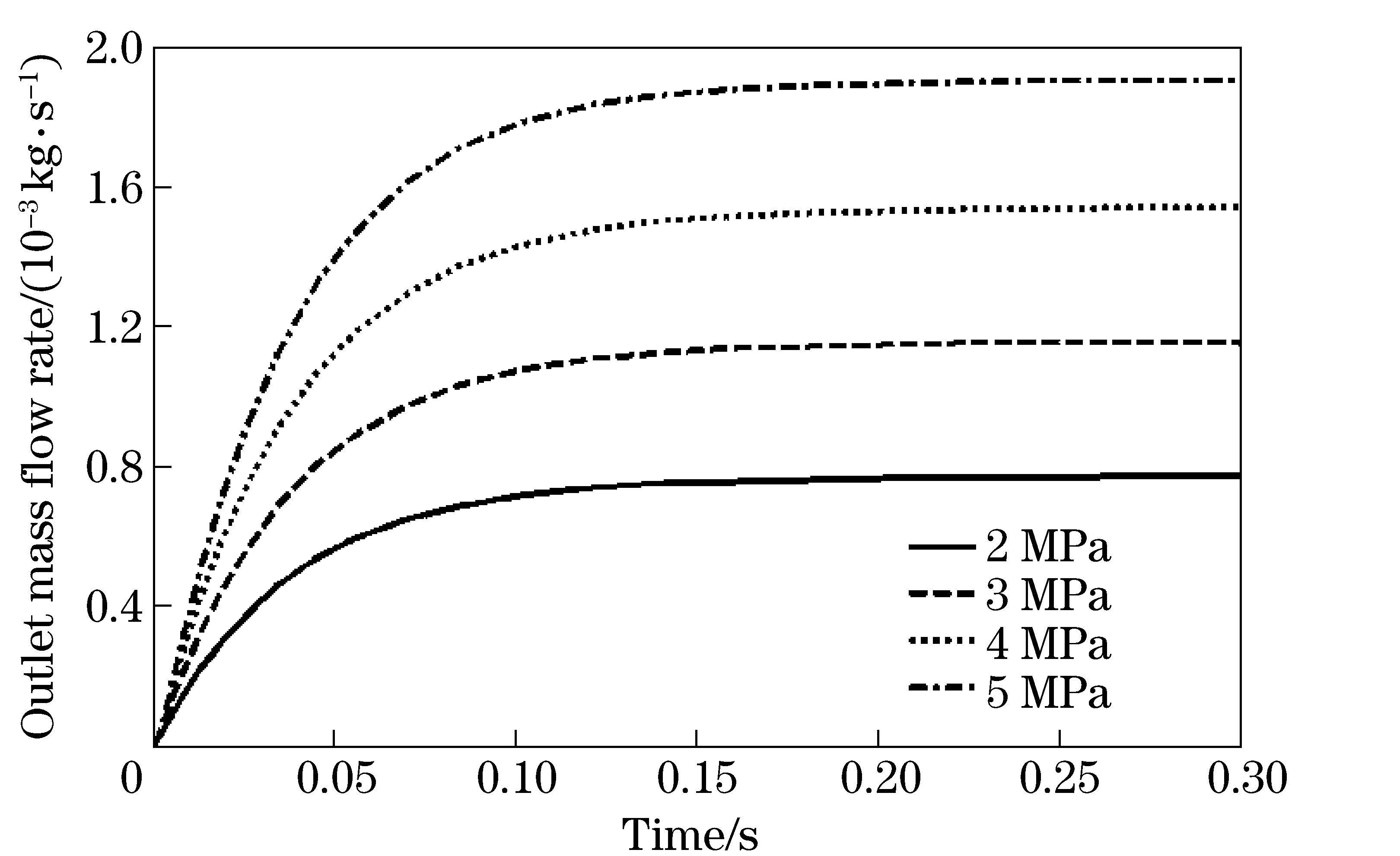
The working condition is defined asxp Working condition is (3) Saturation condition is (4) 3.2 Kinematic equation The position of the poppet can be obtained from equation of the motion. Mx″+(μ+λ)x′+F=0 (5) (6) whereMis total mass of moving parts,xis displacement of the poppet,μis coefficient of friction,λis damping coefficient,dis diameter of poppet shaft,Lis length of poppet shaft contact with bore,ξis radial clearance between bore and poppet shaft.Mcan be expressed as (7) whereMpis mass of poppet,Mnis mass of pushpin,Mpsis mass of pressure spring,Mnsis mass of pushpin spring,Mdis mass of diaphragm. From free body diagram shown in Fig.6, summation of forces can be obtained as F=(Fns+knsxp)-(Fps+kpsxp)-(Fd+kdxp)-PinAp-PoutAd+PoutAop=0 (8) Ap=πR2 (9) whereFpsis the force of pressure spring,Fnsis force of small spring,Fdis the force of diaphragm in the initial position respectively,kpsis the stiffness of pressure spring,knsis the stiffness of small spring,kdis the stiffness of diaphragm,xpis the poppet displacement,Pinis the inlet pressure,Poutis the outlet pressure,Apis the poppet end area,Ris the poppet end radius,Adis the diaphragm area andAopis the opening area. The simulation for poppet motion is carried out and the result is shown in Fig.7. The poppet displacement can be seen from initial position and after a time interval, the poppet remains in steady (equilibrium) condition. Fig.6 Free body diagram of system Fig.7 Response of the poppet 3.3 Pressure and temperature dynamic equations The pressure and temperature dynamic equations based on mass and energy balances[5]are used to obtain the pressure and temperature changes with respect to time. The dynamics equations for a variable volume, single input flow and single output flow can be written as (10) (11) wherem′inis the inlet mass flow rate,m′outis the outlet mass flow rate,Aois the area of low pressure chamber,γis specific heat ratio of gas,Tinis the inlet temperature,Toutis the outlet temperature, andRgis the gas constant. 3.4 Mass flow rate The gas is highly compressible and the mass is constant, the mass flow ratem′ is used to represent flow capacity. (12) (13) Fig.8 Output mass flow rate with various input pressures Eq.(12) and Eq.(13) are used whenPcr>0.528 andPcr≤0.528 respectively[11]. Where,Cdis the coefficient of discharge andAtis the throttle area. The simulation results for mass flow rate passing through the outlet port shown in Fig.8 and it is observed that output mass flow rate increases to a steady state value. Throttle area can be enlarged by increasing the depth of slot cuts on the poppet to achieve high mass flow rate. Experimental setup shown in Fig.9 consists of two solenoid valves, one pressure reducer, two pressure gauges, one pressure sensor, and one miniature pressure regulator. First solenoid valve is used to open and shut-off the flow of gas from high-pressure line. Second solenoid valve is used to drop and hold the pressure in low-pressure line. The pressure reducer is used to maintain the required high-pressure in line. The input pressure gauge indicates the input high-pressure and the output pressure gauge indicates the output low-pressure. Low pressure can also be seen on PC with help of the pressure sensor. Fig.9 Experimental setup The tests were conducted using the experimental setup as shown in Fig.9 in order to verify the simulation results. The experiments and simulation were taken at various inlet pressures of 0.7 MPa, 1 MPa, 2 MPa, 3 MPa, 4 MPa and 5 MPa and results as outlet pressures obtained by adjusting the forced spring. Simulation and experimental results of various outlet pressures with respect to adjusted spring displacement at various inlet pressures are compared and shown in Fig.10. The miniature pressure regulator achieves a significantly faster initial response and a faster convergence to the desired pressure. The prototype is made of aluminum material and gives satisfactory results up-to 5 MPa. Fig.11 shows the simulation results at input pressure of 5 MPa at various pressure spring displacements. The gas in low pressure chamber, the output pressure of regulator, maintains a unit force on the diaphragm and works as air spring. Consequently, the air spring and small spring adds stability and provides a relatively constant output pressure. The miniature pressure regulator manipulates flow in order to control outlet pressure and remains stable. The pressure range of the miniature pressure regulator can be increased by selecting good-quality material for the pressure regulator body and spring, without making changes in dimensions. Fig.10 Experimental and simulation results versus spring displacement Fig.11 Simulation results of effect of the spring pre-load at input pressure 5 MPa The study designed a miniature pneumatic pressure regulator for a hopping robot to hold high pressure, provide stability, robust response and small space. The miniature pneumatic pressure regulator is made of aluminum with 15 g weight, 32 mm height, and 22 mm width, and can hold high pressure up to 5 MPa. The miniature pressure regulator is suitable for portable instruments and mini robotics applications which use high pressure supply. The experimental results are well consistent with the simulation results and showing good performance. The new design of poppet alignment system can avoid side motions of poppet, and provides robustness for reciprocating motion. The miniature pressure regulator is simple in construction and gives satisfied performance. Further experiment will be carried out to estimate lifetime of the miniature pressure regulator and hopping performance of the hopping robot. [1] Boght B V, Damme M V, Ham R V, et al. Pleated pneumatic artificial muscles for robotic applications[C]∥Proceedings of the 2006 IEEE International Conferece on Robotics and Automation, Orlando, Florida, 2006. [2] Van V R B, Bone G M. Accurate position control of a pneumatic actuator using on/off solenoid valves[J]. IEEE/ASME Transactions on Mechatronics, 1997, 2(3): 195-204. [3] Rami E G, Jacques B J, Bruno D, et al. Modeling of a pressure regulator[J]. International Journal of Pressure Vessels and Piping, 2007, 84: 234-243. [4] Rami E G, B. Jacques B J, Pascal G, et al. Stability study and modeling of a pressure regulating station[J]. International Journal of Pressure Vessels and Piping, 2005, 82: 51-60. [5] Nabi A, Wacholder E, Dayan J. Dynamic model for a dome-loaded pressure regulator[J]. Transactions of ASME, Dynamic Systems, Measurement, and Control, 2000, 122: 290-297. [6] Hayashi S. Instability of poppet valve circuit[J]. JSME International Journal Series C, 1995, 38(3): 357-366. [7] Winkler B, Ploeckinger A, Scheidl R. A novel piloted fast switching multi poppet valve[J]. International Journal of Fluid Power, 2010,11(3):7-14. [8] Zhang R, Alleyne A G, Prasetiawan E A. Performance limitations of a class of two-stage electro-hydraulic flow valves[J]. International Journal of Fluid Power, 2002, 3(1):47-54. [9] Yang X, Paik M J, Pfaff J L. Pilot operated control valve having a poppet with integral pressure compensating mechanism: USA, 6745992 [P]. 2004-06-08. [10] Yang X, Stephenson D B, Paik M J. Hydraulic Poppet Valve with Force Feedback: USA, 6869060[P]. 2005-03-22. [11] Zafer N, Luecke G R. Stability of gas pressure regulators[J]. Applied Mathematical Modeling, 2008, 32: 61-82. (Edited by Cai Jianying) 10.15918/j.jbit1004-0579.201524.0107 TP 242 Document code: A Article ID: 1004- 0579(2015)01- 0042- 07 Received 2013-10- 31 E-mail: bitmc@bit.edu.cn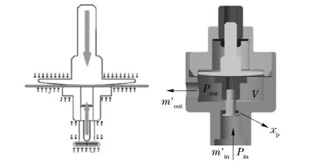
4 Experimental setup

5 Experimental results


6 Conclusion
 Journal of Beijing Institute of Technology2015年1期
- Journal of Beijing Institute of Technology的其它文章
- Numerical simulation of the delay arming process of initiating explosive brakes
- Optimized design of biconical liner by orthogonal method
- Wideband acoustic source localization using multiple spherical arrays: anangular-spectrum smoothing approach
- Influence of eddy current on transient characteristics of common rail injector solenoid valve
- Designing the cooling system of a hybrid electric vehicle with multi-heat source
- Genetic-algorithm-based balanced distribution of functional characteristics for machines