高级引力波探测器的机遇和挑战
2015-07-30 05:01DavidBurnhamTanner
光学仪器 2015年1期
David+Burnham+Tanner

摘要:激光干涉仪引力波观测器已经完成建设,该观测器称为高级LIGO或aLIGO,与2002—2010年间使用的引力波搜寻设备相比,预期灵敏度可以提高一个数量级。目前aLIGO的调试正在试运行。为了达到提升灵敏度的要求,探测器中的所有元件需要提升水平。在此将讨论光电调制器和法拉第隔离器在平均功率百万瓦级分离高质量光束能力的发展,并详述它们在aLIGO输入光学系统中的作用。
关键词:法拉第隔离器; 光电调制器; 引力波; 干涉仪
中图分类号: P 159 文献标志码: A doi: 10.3969/j.issn.1005-5630.2015.01.019
Abstract:The Laser Interferometer Gravitational-Wave Observatory (LIGO) has completed construction of an upgrade, called Advanced LIGO or aLIGO, which is expected to increase the sensitivity tenfold compared to the instruments which conducted searches for gravitational waves during 20022010. Commissioning of aLIGO is presently underway. Achieving the improved sensitivity requires extending the state of the art in all components of the detector. As examples, the development of electro-optic modulators and Faraday isolators capable of delivering high-quality beams at hundreds of Watts of average power are discussed and their performance in the input optics of aLIGO described.
Keywords:Faraday isolator; electro-optic modulator; gravitational waves; interferometer
Introduction
This year is the 25th anniversary of the LIGO project,with the beginning marked by the 1989 submission by Caltech and MIT of a proposal to the NSF[1].The project began in earnest a couple of years later with site selection and civil construction of the two observatories at Hanford,WA,and Livingston,LA,construction of the four 4-km long arms of the vacuum chambers,and design and acquisition of the optical components of the detector.The University of Florida(UF)joined the project in 1996,taking responsibility for the input optics(IO)of the detector.
The design of initial LIGO was kept as simple as possible[2-3].The optical configuration was a power-recycled Michelson with Fabry-Perot arms.The light source was a single-mode 10 W laser at 1 064 nm wavelength.Seismic isolation was provided by a passive stack of springs and masses,aided by a hydraulic external pre-isolator.The four 10-kg,25 cm diameter test masses,the beam splitter,and the power-recycling mirror were hung in single-stage pendulum suspensions.The control system held the mirrors to ±10-13 m.
1 The Input Optics
The IO[3-6] comprises all the optics between the pre-stabilized laser(PSL)and the power recycling cavity,the latter marks the start of the core optics(COC).This is true both for initial and advanced LIGO.A schematic of the IO is in Fig.1.The IO conditions the PSL laser light and delivers it to the interferometer.It provides RF phase modulation for length and alignment,control functions,power control,laser mode cleaning and frequency stabilization,isolation of the laser from interferometer reflected light,optical signal distribution to length,alignment,and intensity controls,and mode matching to recycling and arm cavities.
Most of the IO components in initial LIGO were off-the-shelf commercial parts.This included the electro optic modulators and the Faraday rotator.Mirror blanks were polished to proper radii of curvature and coated by a high-quality ion-beam coating technique.Some mechanical parts were commercial,others were made by the UF Physics Machine Shop.These were installed in the three initial LIGO interferometers during the late 1990s,with the process completed by the end of 2000.
Fig.2 shows view of the input optics in H2,the Hanford 2-km interferometer.The large suspended mirror near the center is MMT3(mode-matching telescope mirror 3),which delivers the full-sized beam to the interferometer.Two of the three mirrors and their suspensions for the mode cleaner are on the left.Steering mirrors and the Faraday isolator are behind MMT3.The large mirror(MMT3)was the first suspended optic installed in LIGO.
2 Advanced LIGO
Advanced LIGO(aLIGO)is designed for a 10× sensitivity improvement,including better low frequency response[7].Because the search volume scales as distance cubed,advanced LIGO will have more than 1000 times more sources within its reach.Predictions for event rates go from ~1 per 10 years to ~1 per week[8].
To achieve this improved sensitivity,essentially everything except for the vacuum system has been replaced.This includes the use of a 180 W laser,quadruple pendulum suspensions,40 kg test masses,active seismic platforms,a signal recycled interferometer,stable recycling cavities,an output mode cleaner,DC readout,and improved thermal compensation.
2.1 IO for advanced LIGO
The higher laser power presented challenges for the input optics[6,9-11].Neither existing commercial phase modulators nor existing commercial Faraday isolators would tolerate 180 W.The former were subject to damage at powers much above 10 W and both devices suffer severe thermal lensing and depolarization when operated at high powers.The thermal lensing is power dependent and could reduce the mode coupling to the following cavities to a very small value.Thermal depolarization in the Faraday reduces the isolation ratio to unacceptably low values.
The Florida group consequently undertook research to improve the performance of these devices.Other steps taken included using lower absorption fused silica mirror blanks,very low-loss mirror coatings,improved baffling of stray light,improved metrology,in-vacuum photodetectors,and many other things that also were being advanced by the core optics,instrument sensing and control,and other groups building aLIGO.
2.2 The aLIGO EOM
A review of electro-optics materials led to the selection of rubidium titanyl phosphate(RbTiOPO4 or RTP)as the most promising modulator material for aLIGO[6].Laboratory experiments corroborated this choice.
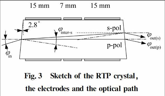
Fig.3 shows a sketch of the RTP crystal,the electrodes,and the optical path as used in aLIGO.The three electrodes,permitting one crystal to provide phase modulation at three distinct frequencies.The wedge and refractions of the two polarizations are shown,with the angles greatly exaggerated.
To avoid the unwanted generation of amplitude modulation by polarization modulation because of imperfect alignment of the incident light and also to avoid etalon interference effects we chose to wedge the faces of the RTP crystal.The birefringence of the RTP material separates the two polarizations and avoids polarization rotation that would lead to amplitude modulation.
Another very positive effect of this is that the two polarizations are of very high purity,better than 105∶1.The crystal faces are antireflection coated,giving less than 0.1% remaining reflectivity.To reduce the number of optical surfaces,a single long crystal with three separate pairs of electrodes is used to produce the three required modulation frequencies.A housing,including RF matching circuits was designed for the modulator.
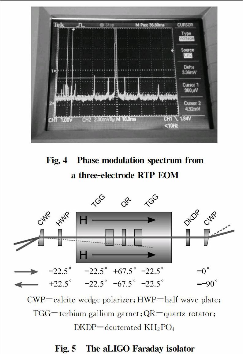
showed no damage.There was a slightly anisotropic thermal lens at these powers,with focal length of 4 000 mm or greater.This is in contrast to the standard material,LiNbO3,which had a slightly shorter focal length thermal lens with only 10 W incident.RTP modulators have been installed and operated at both LIGO sites for almost three years and perform satisfactorily.Typical phase modulation indices are up to 0.4,with residual amplitude modulation less than 3×10⁻⁴ W/rad.Fig.4 shows the output of the modulator as measured by an optical spectrum analyzer,showing sideband frequencies of 9.1,24.1 and 45.5 MHz.
2.3 aLIGO Faraday isolator
For the Faraday isolator(FI),we use a custom design with passive compensation of thermal lensing[12] and thermal depolarization[13].Fig.5 shows a cartoon of the isolator,which was developed in collaboration with IAP,Nizny Novgorod.It uses two TGG crystals with a quartz rotator between.In high power operation,there is a non-uniform temperature profile in the TGG crystal.The temperature is highest at the center of the laser beam and falls off to ambient at the edges.This profile causes thermal depolarization because the Verdet constant V is temperature dependent.Ideally the polarization in a Faraday rotator is perfectly linear,and the plane of polarization rotates smoothly as the beam traverses the crystal,with the angle of rotation per unit length per unit magnetic field given by V.With a non-uniform temperature in the crystal some parts of the beam rotate more than others,causing depolarization.The use of two crystals,the reciprocal quartz rotator,and a custom magnet design in the aLIGO FI causes the thermal depolarization induced by the first TGG crystal to be taken out by the second TGG crystal[13].
The Faraday also employs a similar trick to compensate for thermal lensing[12].The refractive index of TGG depends on temperature,so that the velocity of light traveling in the heated center of the crystal is slower than in the cooler outer part,leading to a graded-index lens effect which can be quite substantial.The isolator incorporates a negative dn/dT crystal(deuterated KH2PO4 or DKDP)whose thickness is chosen so that the positive lenses in the TGG crystals and the negative lens in the DKDP combine to have no net focusing effect.The FI also has an adjustable half wave plate to set the output polarization and calcite wedge polarizers(with up to 105 ∶1 separation of the two polarizations)at input and output.
Figure 6 shows the performance of the two Faraday isolators of aLIGO as incident power is increased up to(in the LHO case)140 W.The isolation ratio was reduced at high power settings.This is attributed to an overall warming of the crystals.(The Verdet constant is inversely proportional to temperature.)The half-wave plate was not adjusted during these measurements.The isolation ratio could be partially recovered by adjusting the waveplate,but 30 dB meets the advanced LIGO requirements.
2.4 Installation in advanced LIGO
Figure 7 shows
part of the aLIGO input optics,located in the HAM2 of the H1 interferometer.The Faraday isolator can be seen just above and to the right of picture center.The tower partially seen at the left is the triple-pendulum suspension for one mode cleaner mirror.Many other components are visible;indeed there is little uncommitted space here.The differences with the corresponding space for initial LIGO(Fig.2)represent the additional complexity and sophistication of advanced LIGO.
3 Conclusions
Advanced LIGO is poised to begin receiving gravitational-wave signals from sources up to 200 megaparscs(6×10⁸ light years)from Earth.One may expect exciting times ahead as the instruments reach their design sensitivity.
Acknowledgements
The input optic construction was funded by a subcontract from the LIGO Laboratory.Research at the University of Florida was supported by National Science Foundation grants PHY-1205512 and PHY-0969935.I thank Rick Savage for a careful reading and for supplying the image in Fig.7.This document has been assigned LIGO Laboratory document number P1400211.
References:
[1] ABRAMOVICI A,ALTHOUSE W E,DREVER R W P,et al.LIGO:the laser interferometer gravitational-wave observatory[J].Science,1992,256:325-333.
[2] ABBOTT B,ABBOTT R,ADHIKARI R,et al.Detector description and performance for the first coincidence observations between LIGO and GEO[J].Nucl.Instrum.Methods A,2004,517:154-179.
[3] ABBOTT B P,ABBOTT R,ADHIKARI R,et al.LIGO:the laser interferometer gravitational-wave observatory[J].Rep.Prog.Phys,2009,72:1-25.
[4] CAMP J,REITZE D,TANNER D B,et al.Input/output optics conceptual design,LIGO Document[DB/OL].1996,No.LIGO-T960170-00-D.
[5] ADHIKARI R,DELKER T,REITZE D,et al.Input/output optics preliminary design,LIGO Document[DB/OL].1997,No.LIGO-T970144-00-D.
[6] DOOLEY K L,ARAIN M A,FELDBAUM D,et al.Thermal effects in the input optics of the enhanced laser interferometer gravitational-wave observatory interferometers[J].Rev.Sci.Instrum,2012,83:1-12.
[7] AASI J,ABBOTT B P,ABBOTT R.Advanced LIGO,LIGO Document[DB/OL].2014,No.LIGO-P1400177.
[8] ABADIE J,ABBOTT B P,ABBOTT R,et al.Predictions for the rates of compact binary coalescences observable by ground-based gravitational-wave detectors[J].Class.Quant.Grav,2010,27:173001.
[9] MUELLER G,REITZE D,RONG H S,et al.Reference design document for the advanced LIGO input optics,LIGO Document[DB/OL].2000,No.LIGO-T010002-00-D.
[10] AMIN R,MUELLER G,RAHKMANOV M,et al.Advanced LIGO input optics subsystem conceptual design document,LIGO Document[DB/OL].2002,No.LIGO-T020027-00-D.
[11] ARAIN M A,LUCIANETTI A,MARTIN R,et al.Input optics subsystem preliminary design document,LIGO Document[DB/OL].2007,No.LIGO-T060269-01-D.
[12] MUELLER G,AMIN R S,GUAGLIARDO D,et al.Method for compensation of thermally induced modal distortions in the input optical components of gravitational wave interferometers[J].Class.Quantum.Grav,2002,19:1793-1801.
[13] PALASHOV O V,ZHELEZNOV D S,VOITOVICH A V,et al.High-vacuum-compatible high-power Faraday isolators for gravitational-wave interferometers[J].Opt.Soc.Am.B,2012,27:1784-1792.
(编辑:刘铁英)
猜你喜欢
九江学院学报(自然科学版)(2022年2期)2022-07-02
计测技术(2020年6期)2020-06-09
现代装饰(2020年4期)2020-05-20
百科探秘·航空航天(2020年12期)2020-01-22
航天电子对抗(2019年4期)2019-06-02
制导与引信(2017年3期)2017-11-02
科学大众(中学)(2016年9期)2016-12-29
太空探索(2016年4期)2016-07-12
太空探索(2016年4期)2016-07-12
海峡姐妹(2016年2期)2016-02-27