
Fuzzy Model Free Adaptive Control for Rotor Blade Full-Scale Static Testing
2015-08-07 10:54LIAOGaohua廖高华WUJianzhong乌建中
LIAO Gao-hua(廖高华),WU Jian-zhong(乌建中)
1 School of Mechanical Engineering,Tongji University,Shanghai201804,China
2 Nanchang Institute of Technology,Nanchang 330099,China
Fuzzy Model Free Adaptive Control for Rotor Blade Full-Scale Static Testing
LIAO Gao-hua(廖高华)1,2,WU Jian-zhong(乌建中)1*
1 School of Mechanical Engineering,Tongji University,Shanghai201804,China
2 Nanchang Institute of Technology,Nanchang 330099,China
To elim inate the node traction coup ling during w ind turbine blade full-scale static testing,a model free adaptive control algorithm is presented based on fuzzy control performance function com pensation.Based on the universalmodel theory,the fuzzymodel free adaptive control(FMFAC)algorithm is designed by configuring the spot static testing experiences as com pensation function F(·).Then the algorithm im p lementation process is provided and its quick convergence is proved.Using software to establish static load coup ling model of multi-nodes,simulate and verify the validity of FMFAC algorithm,which is applied to wind turbines blade full-scale static testing.The results show that the adaptive decoupling ability of FMFAC is better.The traction of four load points can stay steady and change coordinately.Processerror is not over±6 kN.The error rate is lower than 1%in special phase.This algorithm effectively elim inates the traction coupling of the static testing process,and makesw ind turbine blade testing steadily.
wind turbines;fuzzy control performance;decoupling; model free adaptive control(MFAC)algorithm;static testing
Introduction
As one of the core component of w ind turbines,all the blades new ly developed or changed with significant revisions need tomake static loading test for checking the static strength reserved[1-2].Static testing is accomplished in a number of ways.Hydraulic actuators have also been used in the past but the large displacements required for long bladesmake them an expensive option.Another way of performing a static test is to hang ballast weights from the blade at specified locations,but loading accuracy is difficult to guarantee.Themost common of these uses an electric w inch system,due to ease of control.The test needs to coordinate the force of all the load points.The node traction mutation is very easy to damage the blade.The blade loading points are coupling with each other during the testing process.Themore tractions increase,themore seriously blades bending and coupling.It's easy to cause blade vibrating and affect testing precision[3-5].Besides,controlled objects always change in static testing process.Multi-variable system neural network decoupling control method achieves open-loop decoupling by training neural network[6-8].
The above control algorithms aremainly based on models' adaptive control,or control by know ledge derivation according to somemodels'parameters.All cannot do without depending on the system models[9-10].Because of the blade shape structure complex,buildingmathematicalmodels is noteasy.A distributed multi-node loading system based on PID algorithm is designed,which does not adopt the w idely used semi-automatic loadingmode[11-13].For the test of static loading small power w ind turbine blade,the PID control strategy can meet the requirement of precision.With the blade's size increasing,the traction value increases correspondingly.It willmake the same node coupling more seriously,which will cause higher requirements on the decoupling ability control algorithm.
For the above reasons,the coupling is strong in the static testing process and it's hard to build system models.Based on the characteristics analysis of static loading coupling,fuzzy model free adaptive control(FMFAC)algorithm is designed with fuzzy control theory and function compensation. Meanwhile,the convergence and divergence are derived in the paper.Stimulate and analyze FMFAC algorithm by building static loading coupling model ofmulti-nodes.This algorithm is applied in w ind turbine blades full-scale static testing system. The static loading test includes4 loading phases,tomake blades loading state steady.
1 FMFAC Algorithm Design
1.1 FM FAC algorithm analysis
In a discrete-time nonlinear system,the controlled system is represented as:

where u(k)and y(k)identify the input and the output of system;m and n are for their orders,respectively.
Given that{ u(k-1),y(k)}is the observation data of system at k moment,while y0(k+1)is the expected output at k+1 moment.Find the optimal controlled quantity as u(k)to make the output as y0(k+1).The existence of some pseudo gradientφ(k)has been proved[14].Do partial format linearization for system(1),and get the basic expression of model free adaptive control(MFAC)algorithm by further transform ing:
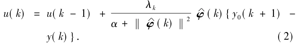
From the algorithm control Formula(2),the controlled system is not related with mathematics model of controlled object,and it is only designed according to system's input and output data.If the valuation ofφ(k)is inaccurate when using MFAC algorithm,it will seriously affect system's control.To avoid it,modify Formula(2)to:

whereλkis the step sequence,chosen by on-site situation,to avoid the force varying greatly in loading process;αis the weight factor,chosen by on-site situation,to avoid the loading speed too slow;εis the threshold value,avoid too much input motivation;and F(·)is for function compensation.
When Formula(3)can be used,the essential condition is thatφ(k)'s valuationφ∧(k)can be got in real time and have enough accuracy.To avoid system too sensitive about several abnormal data,for the estimate ofφ(k),use the follow ing formula function:

where y*(k)is the expected output at k moment.
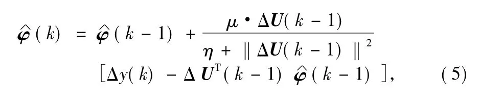
whereμis the study step;ηis the penalty factor;andΔU(k-1)is the difference between tw ice input values.Choose parameters above according to the actual loading experience, and adjust in real time by F(·)function.Ifthen
1.2 F(·)function com pensation design
For the analysis about the traction's output characteristicsof all static loading nodes,the traction always fluctuates around the expected value of¯y.Use mathematical relationship to describe four characteristics of system's output y(k)variation.The illustrations are as follows.
In zone 1:¯y-y(k)≥0 and y(k-1)-y(k)≥0.
In zone 2:¯y-y(k)>0 and y(k-1)-y(k)<0.
In zone 3:¯y-y(k)≤0 and y(k-1)-y(k)≤0.
In zone 4:¯y-y(k)<0 and y(k-1)-y(k)>0.
Define Q(k)=(¯y-y(k))(y(k-1)-y(k));when Q(k)≥0,y(k)is changed in zone 1 and zone 3;when Q(k)<0,y(k)is changed in zone 2 and zone 4.
To ensure the self-adaptive ability of MFAC algorithm,use variation characteristic of parameter Q(k)as the strengthened item's control rule,put spot static loading experience into MFAC,and apply fuzzy control strategy to add compensation F(·)function.
In the actual loading process,Fiare dependent variables and Viare independent variables.The process is to control node traction Fihydraulic w inch speed Vi.The traction expected value,expected value difference e and the variance ratio d e/d t are the inputs of F(·)function.The clarified inputs are e and ec.The membership function of E is the cross of gauss-type function and trigonometric function.The membership function of ecis full overlap of symmetrical triangle.Membership function of inputs and outputs is shown in Fig.1.
According to the method of Mamdani reasoning,choose Max-M in method of weighted mean,as follows:

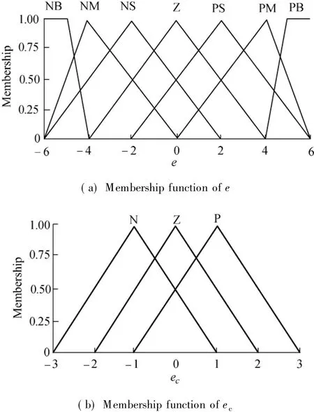
Fig.1 Membership function of inputs and outputs
The control rules stand for the experience conclusion of static loading process.Refer to the characteristic curve analysis of output traction;there are 49 control rules for the loading process reasoning as shown in Table 1.In practical applications,each loading node has different value,so integrate the traction values of all nodes into one for easier control.The average traction value of all the loading nodes is expressed as:

where kk=Fkmax/F0maxis the proportionality coefficientand Fkis the k th value of traction.

Table 1 Fuzzy control rules
1.3 FM FAC algorithm diagram
Make the block diagram of FMFAC algorithm during the static loading process,as shown in Fig.2.The FMFAC algorithm implementing steps and process are as follows.
IN:the current and target values of traction,hydraulic w inch speed
OUT:hydraulic w inch speed Vi(k+1).
Step 1 By using observed input&output data{Fi(k),Vi(k)}and identification algorithm,derive the estimated valueof pseudo partial derivativeφ(k).
Step 2 According to the expected traction value(k+ 1)of loading process,get the error e(k)at the moment.By inputting expected traction value(k+1),error e(k)and error change rate d e(t)/d t to strengthened function,and get F(·)function compensation.
Step 3 According to F(·)function and MFAC algorithm,get the hydraulic w inch speed Vi(k)act on the test process at themoment k.
Step 4 The obtaining results(namely k moments of the hydraulic w inch speed value)Vi(k)applied to the static loading process,to obtain a new set of input and output data{Fi(k+ 1),Vi(k+1)}.
Step 5 Repeat Step 1 to Step 4,and get a new setof data {Fi(k),Vi(k)},k=1,2,…,continued until the end of the simulation.

Fig.2 FMFAC algorithm diagram
2 Convergence and Divergence Analyses of FMFAC Algorithm
The basic part of FMFAC algorithm is MFAC,and the application condition of it is that both identification algorithm and control strategy are convergent.For a time lag system,if u(k)≠u(k-1),then one vectorφ(k)mustexist in order to make Formula(3)true for any adjacent two sets of data{u(k-1),y(k)}and{u(k),y(k+1)}.The inevitability ofφ(k) existence and the convergence of the identification algorithm have been proved[15-16].The starting point of control strategy convergence is as follows:

where y(k+1)is the system outputwith u(k)effect.
Further derive from Eq.(8)
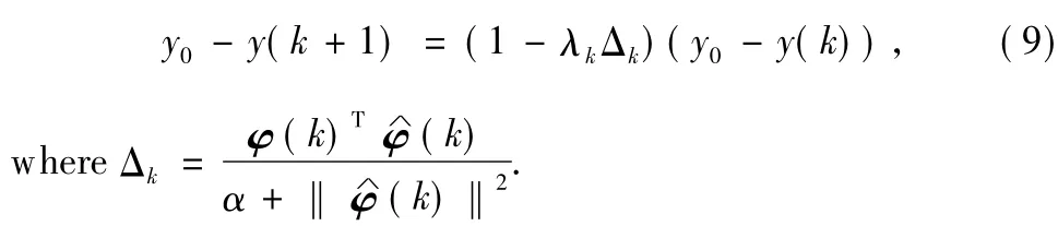
As the first section describes,get the estimated valueφ∧(k +1)ofφ(k+1)from universalmodel,and then get the system output y(k+2)with the control strategy(9)effect.Again and again until we get the output y(k+h)at k+h moment,expressed as:
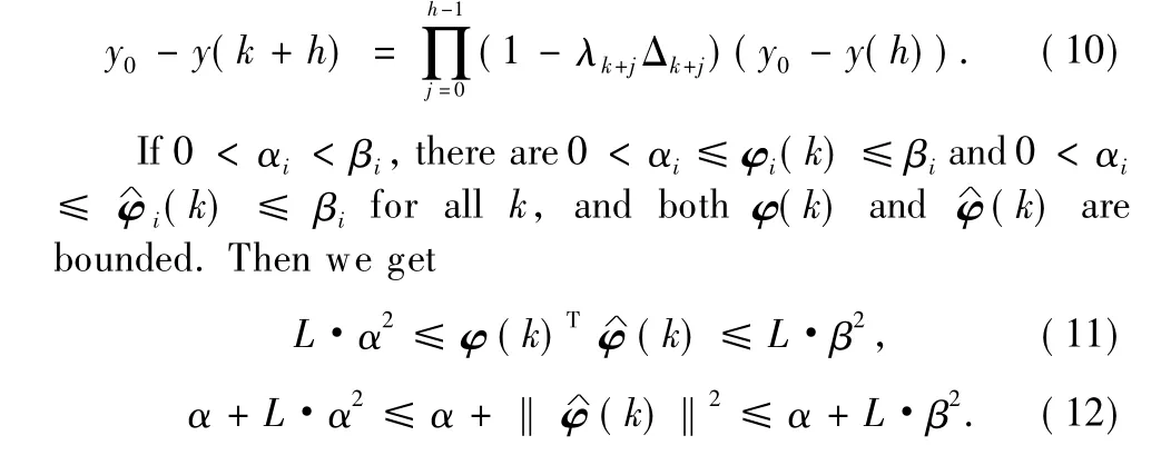
Combine Formula(11)with Formula(12),and get

Letλk>0.Formula(13)can be changed into:
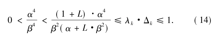
According to the infinite product theorem,we get

The above derivation has proved quick convergence of MFAC algorithm.If the controlled object changes,the identified values of characteristic parameterφ(k)are expressed in both the parameters and the structure.When the amplitude has little change,only one single regulator,the system output y(k)will converge to the expected value.
3 FMFAC Algorithm Decoupling Simulation
AMESim and Matlab/Simulink softwares are used together to build static loading coupling simulation models of multinodes.The output is the traction Fiof allnodes,and the input is the speed Viof all variable stroke pump,shown in Fig.3.Set the stiffness and damping between loading points of the controlled objects as the cross coupling,and the random variable stiffness and damping of the coupling degree are the same.During the loading process,use FMFAC and dynamic master-salve PID control algorithm separately,to check selfadaptive ability of FMFAC control algorithm.
According to the practical experience,set sampling period T=0.05 s.The values of related control parameters are:kp= 15,ki=0.1,and kd=0.Algorithm decoupling and its error (amplification)curve are shown in Fig.4.From the process curve,the traction of three loading nodes increases progressively.The nodes with stronger traction have larger fluctuations relatively.When the traction is small,the decoupling ability of the algorithm is better.But the more tractions increase,the more nodes coupling increases in the same loading phase.The error of node 1 is almost 6%.It indicates that the decoupling ability of the control algorithm is relatively poor with strong coupling conditions.
According to the practical loading experience,sampling period T=0.05 s,related control parameters initial values are: λk=10,α=3.5,μ=0.4,η=2,ε=10-5,=0.3, and the simulation result is shown in Fig.5.From the process curve,because of cross coupling among the nodes in the loading process,the traction of each node fluctuates progressively,and the nodes fluctuatemore seriously with stronger traction.After using FMFAC algorithm,the traction of each node is always around the ideal output value,and the variation trend is basically consistent.From the traction error curve of loading node 1,error values also show the increasing trend with the increasing of traction,and the error value is far less than 4%in the loading process.It's proved that the control algorithm has better self-adaptive decoupling ability.
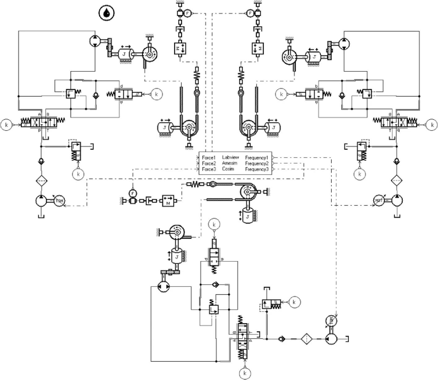
Fig.3 Static load coupling equivalentmodel
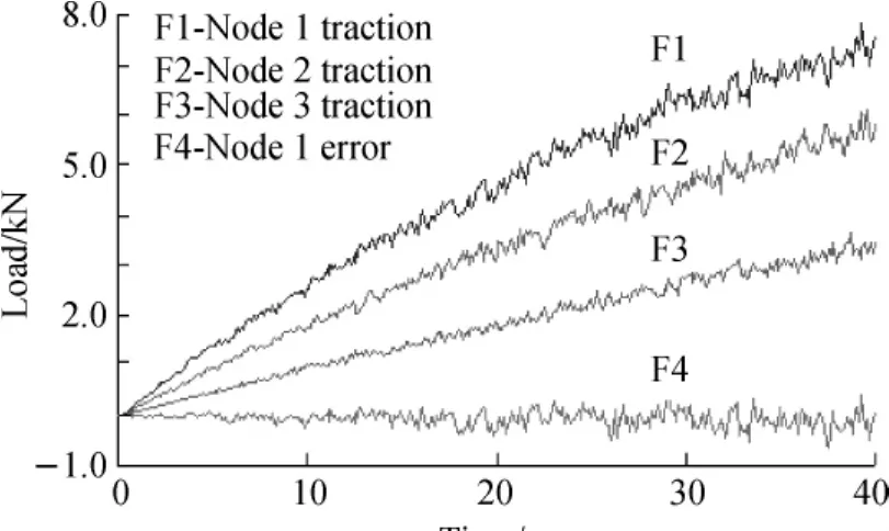
Fig.4 PID algorithm decoupling and its error curve
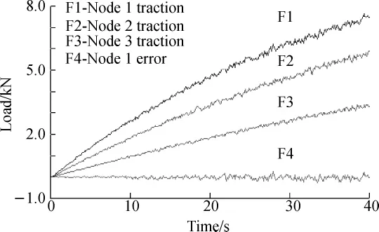
Fig.5 FMFAC algorithm decoupling and its error curve
4 Test of Static Loading Control Algorithm
Wind turbine blades root is fixed on the barrel type load bearing,many load trestles take the horizontal traction mode, and control system uses the two-level network communication
This test system mainly includes an uppermonitor, themain controller,an electric control system,etc.Use the monitor system to coordinatemulti-nodes loading control,which can freely sw itch between automatic and manual operations,display current loading stage,and save real time in loading test data.The on-site testsolution is shown in Fig.6.The testobject is aeroblade2.0 w ind turbine blade,whose power rating is 2 MW.It belongs to the w ind turbine blades with high power rating.The blade full-scale static loading test has four nodes,usingmultistage continuous loadingmode to avoid damaging the blade in the test process.The loading process is divided into four stages.According to the IEC61430-23 level,the traction in 100%stage should stay at least 10 s,and the whole loading process is shown in Fig.7.

Fig.6 Wind turbine blade static load test scheme
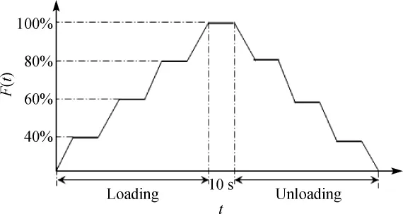
Fig.7 Static loading stage diagram
The static loading test uses FMFAC control algorithm,and choosesλk,α,μ,andηas parameters(initial values)according to the loading experience.The traction and error ofw ind turbine blade Flapw ise loading surface are shown in Fig.8.From the traction curve of all the loading surfaces,the tractions of all loading points change coordinately.For each loading stage,the error is grow ing together with traction.With the blade bending grow ing larger,the blade stiffness values increase accordingly. So the coupling degree of nodes is more serious.Introduce compensation function as experience compensation,and FMFAC algorithm controls traction at around the expected value.Make sure the traction error basically remains within ±6 kN,themaximum process error is±4%,and the special stage error only±1%.The algorithm effectively reduces the coupling between nodes and gets better control effect.

Fig.8 Flapwise loading surface traction test variable and error
5 Conclusions
With the full-scale static loading process characteristic analysis of w ind turbine blade of MW type,FMFAC control algorithm is designed to apply to the loading test.By the traction increasing,the blade bending becomes larger with stiffness values grow ing larger accordingly.It leads to a more serious coupling degree between nodes.The error displays grow ing trend basically.Improper control may easily damage the blade.For the full-scale static loading test of w ind turbine blade of smallminiwatt type,using dynamic master-slave PID control algorithm is enough for the accuracy requirement. However,with the blade type grows,the required traction value will increase accordingly.It will cause the nodes coupling degreemore and more serious in the same loading phase,so it needs higher decoupling ability of control algorithm.FMFAC control algorithm has fast convergence and strong decoupling ability.Introduce the fuzzed on-site experience and integrate it into the algorithm.It effectively reduces the coupling degree in the full-scale loading process.The traction between nodes can keep steady and change coordinately,and the traction is controlled ataround the expected value.Thatmeets the needs of practical applications.
[1]Movaghghar A,Lvov G I.A Method of Estimating W ind Turbine Blade Fatigue Life and Damage Using Continuum Damage Mechanics[J].International Journal of Damage Mechanics,2012,21(6):810-821.
[2]Kishinam i K,Taniguchi H,Suzuki J.Theoretical and Experimental Study on the Aerodynam ic Characteristics of a Horizontal Axis W ind Turbine[J].Energy,2005,30(11): 2089-2100.
[3]Malhotra P,Hyers R W,Manwell J F,et al.A Review and Design Study of Blade Testing Systems for Utility-Scale W ind Turbines[J].Renewable and Sustainable Energy Reviews,2012,16(1):284-292.
[4]Chen J,Wang X D,Shen W Z,et al.Optimization Design of Blade Shapes for Wind Turbines[J].Journal of Mechanical Engineering,2010,46(3):131-134.(in Chinese)
[5]Wang X D,Wang L C,Li P,et al.Design and Trial of MW W ind Turbine Blade Static Loading Control System[J]. Mechanical Science and Technology for Aerospace Engineering,2012,31(5):806-809.
[6]Yang J S,Peng C Y,Xiao J Y.Structural Investigation of CompositeW ind Turbine Blade Considering Structural Collapse in Full-Scale Static Tests[J].Composite Structures,2013,97(3): 15-29.
[7]Chai T Y,Wang G.Globally ConvergentMultivariable Adaptive Decoupling Control and Its Application to a Binary Distillation Column[J].International Journal of Control,1992,55(2): 415-429.
[8]Jensen FM,Falzon B G,Ankersen J,et al.Structural Testing and Numerical Simulation of 34m CompositeWind Turbine Blade[J].Composite Structures,2006,76(1/2):52-61.
[9]Kirikera G R,Shinde V,Schulz M J.Monitoring Multi-site Damage Grow th During Quasi-Static Testing of a W ind Turbine Blade Using a Structural Neural System[J].Structural Health Monitoring,2008,7(2):157-183.
[10]Liang L H,Liu Q,Zhao L L.Reseaarch on Feed-Forward Compensation Decouple Control for the Electro Hydraulic Load Simulators of Fin Stabilizer[J].China Mechanical Engineering,2007,18(4):439-441.(in Chinese)
[11]Daynes S,Weaver P M.Design and Testing of a Deformable Wind Turbine Blade Control Surface[J].Smart Materials and Structures,2012,21(10):1-11.
[12]Zhang L A,Wu J Z,Wang W D.Design of MW Blade Static Loading System[J].Control Engineering of China,2011,18 (6):986-989.(in Chinese)
[13]Zhang L A,Wu JZ,WangW D,etal.Design and Trialof MW W ind Turbine Blade Static Loading Control System[J].China Mechanical Engineering,2011,22(18):2182-2185.(in Chinese)
[14]Cao R M,Hou Z S.Simulation Study on Model-Free Control Method in Linear Motor Control System[J].Journal of System Simulation,2006,18(10):2874-2878.(in Chinese)
[15]Ma J,Chen Z Y,Hou Z S.Modal Free Adaptive Control of Integrated Roll Reducing System for LargeWarships[J].Control Theory&Applications,2009,26(11):1289-1292.(in Chinese)
[16]Huang X M,Zhang L A,Wei X T.D-MFAC Algorithm Control of Megawatt Wind Turbine Blade Static Loading Process[J]. Journal of Zhejiang University:Engineering Science,2012,46 (12):118-123.(in Chinese)
[17]Han Z G,Wan L.Adaptive Control Law by Universal[J]. Journal of Natural Science of Heilongjiang University,1999,16 (1):42-47.
[18]Zhang L A.Research on Key Technology of MW W ind Turbine Blade Loading System[D].Shanghai:TongjiUniversity,2011. (in Chinese)
TH122
A
1672-5220(2015)04-0536-05
date:2014-09-08
National Natural Science Foundation of China(No.51567018)
*Correspondence should be addressed to WU Jian-zhong,E-mail:tjjd328@163.com
 Journal of Donghua University(English Edition)2015年4期
- Journal of Donghua University(English Edition)的其它文章
- Numerical Reality Method of the M icroburst Model
- Corporate Governance,Government Regulation and Bank Stability
- Cracking Patterns of Shear Walls in Reinforced Concrete Structure due to Strong Earthquake Based on Mohr-Coulomb Criterion
- Cooperative Compressive Spectrum Sensing in Cognitive Underwater Acoustic Communication Networks
- Numerical Simulation of Gas-Solid Two-Phase Flow in Reverse Blow ing Pickup Mouth
- Bottleneck Identification and Prediction of Wafer Fabrication Systems in Transient States