
Influence of the underlap in the poppet valve on its performance
2015-10-29 07:15XiaoxiaGUOYanweiMAYongZHANGJiahaiHUANGLongQUAN
机床与液压 2015年4期
Xiao-xia GUO, Yan-wei MA, Yong ZHANG,Jia-hai HUANG,*, Long QUAN
(1Key Lab of Advanced Transducers and Intelligent Control System, Ministry of Educationand Shanxi Province, Taiyuan University of Technology, Taiyuan 030024, China)(2Technology Center of Taiyuan Heavey Machinery Group Yuci Hydraulic Industry, Yuci 030600, China)
Influence of the underlap in the poppet valve on its performance
Xiao-xia GUO1, Yan-wei MA2, Yong ZHANG1,Jia-hai HUANG1,2*, Long QUAN1
(1KeyLabofAdvancedTransducersandIntelligentControlSystem,MinistryofEducationandShanxiProvince,TaiyuanUniversityofTechnology,Taiyuan030024,China)(2TechnologyCenterofTaiyuanHeaveyMachineryGroupYuciHydraulicIndustry,Yuci030600,China)
Valvistor valve adopted the flow feedback principle has many benefits including low leakage and big flow capacity and an economical design and has been widely used in hydraulic systems. The underlap in the poppet valve has a significant effect on the flow capacity and static performance. In this paper, the simulation model of valvistor valve was established by using the simulation software—SimulationX. Experiments were made to validate the simulation model. The effects of different underlap in the poppet on performance of the spoolwerecompared. The results show that the underlap in the poppet valve always has to increasethe pre-opening amount to guarantee the stability, but the underlap will reduce the flow capacity of the valve. The results provide a theoretical basis for the performance improvement of the valve.
Cartridge valve, Flow amplifier, Underlap in the slot
1 Introduction
The valvistor valve has some advantages, such as large flow, simple structure, easy processing, good static and dynamic performance, etc. Valvistor valve is widely applied in various engineering machinery and hydraulic systems, and the domestic and foreign scholars have studied on its performances in details. The dynamic mathematical models of Valvistor main valve and pilot valve are established and simplified to the first-order model and its static and dynamic characteristics are studied in details by Eriksson[1-2]. Literature[3] applied valvistor valve flow amplifying principle to three four-way proportional direction valve. Literature[4] established 3D model of the new type of proportional direction valve, and carried out the simulation. The results showed that the valve had good static and dynamic performances. Literature[5] proposed anew concept of two-way valvistor, experimental research showed that the flow capability, static and dynamic characteristics of the new valve were improved obviously. Literature[6] studied the main valve core displacement electric closed loop feedback proportional throttle valve by simulation, the results showed that the electric closed-loop proportional cartridge valve had excellent control characteristic and dynamic characteristic.
Domestic and foreign scholars have conducted a detailed study on valvistor valve performances. But the study about the cause of increasing underlap in the poppet valve and the effects of underlap on the performance of poppet valvewere less,therefore studying the effect of underlap on performance of the valve core, and then selecting the appropriate underlap is of great significance to improve the performance of poppet valve.This paper establisheda simulation model by using SimulationXto study valvistor valve performances, and the simulation results were verified by experiments, and the effect of the underlap on the performance of the valve corewas studiedas well.
2 The working principle and mathematical model
The working principle of valvistoris given in Fig.1. When pilot valve port is closed, the control chamber is filled with oil which flows through slot in the main valve from inlet of main poppet. Due to same pressure of upper and lower chambers, spring force and the upper and lower area differential, main poppet is in the state of shut. Then the pressure of the control chamber gets decreased when the oil flows through pilot poppet to the outlet of main poppet, and main poppet moves up when pilot valve port opens. It comes to steady state when main poppet stops moving with the flow of feedback notch and pilot poppet being the same.
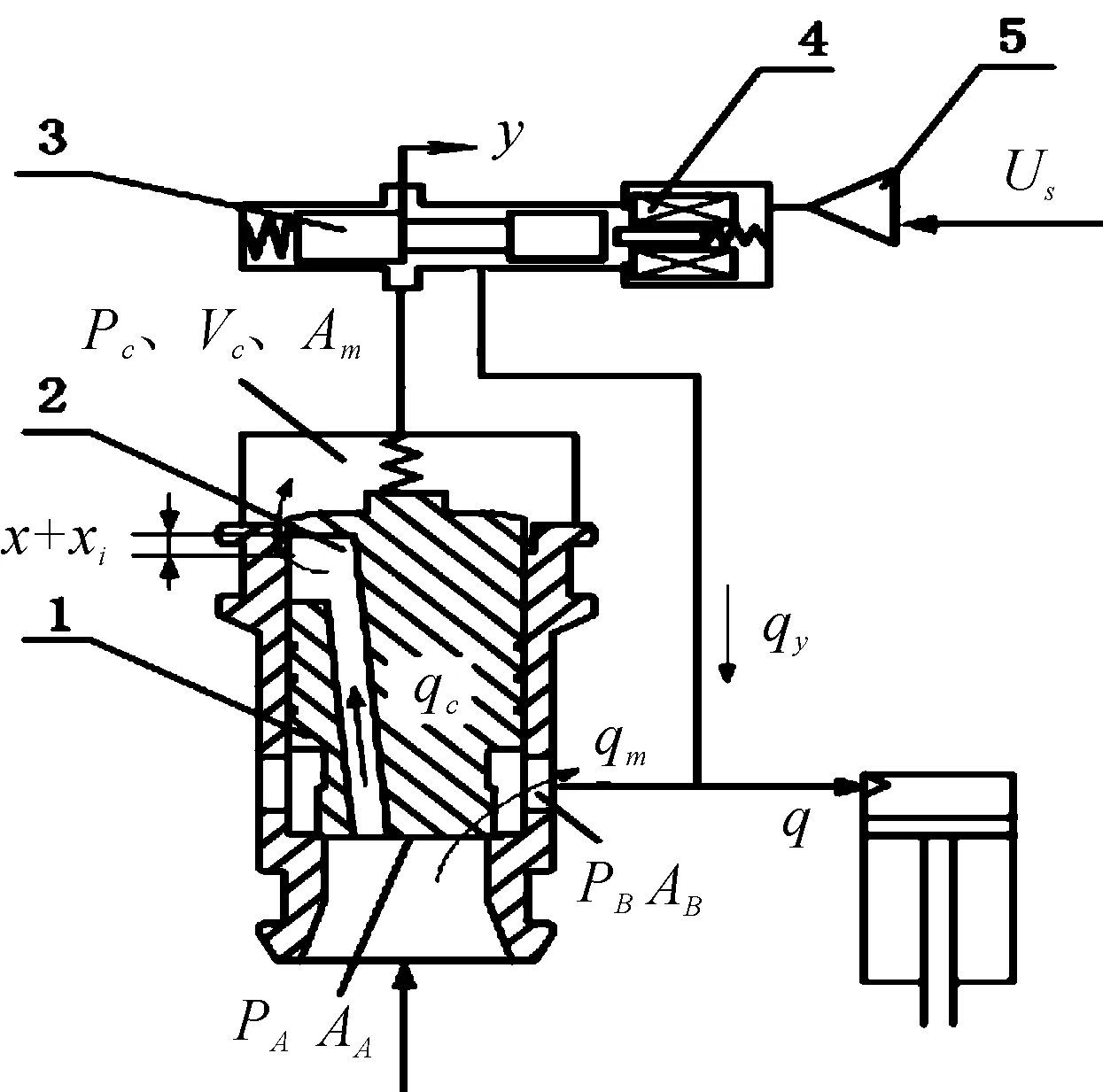
1.mainpoppet; 2.slotin the main valve; 3.pilotvalve; 4.solenoid; 5.amplifier
Fig.1 Working principle of the Valvistor valve
During the process of valve core movement, assume the inlet pressurePA, outlet pressurePBare constant. The flow through the main orifice and dynamic equilibrium equation of the valve spool could be obtained as follows:
(1)
(2)
The flow through the pilot valve port could be evaluated as follows:
(3)
The flow through the feedback notch and pressure of control chamber could be calculated as follows:
(4)
(5)
(6)
When the valve spool is stable, neglecting spring force and flow force, the equation (2) can be modified as:
(7)
At this time the flow through the feedback notch and pilot valve are the same.
(8)
The static mathematical model of the main valve is as follows:
(9)
Compared with the main valve, pilot valve dynamic characteristic could be ignored. The transfer function betweenYandQcould be written as follows:
(10)
Ignoring the damping coefficientBmand steady fluid force, the system stability condition is:
(11)
PA0,PB0,y0are the pressure and displacement of pilot valve, respectively, when the valve core is steady. From stability conditions (11), the valve core stability is connected with pilot valve openingy0, control cavity volumeVC, narrow groove widthWCand other factors.
3 Simulation and experimental study
The simulation model of size 16 valvistor established by using SimulationXis shown in Fig.2. The model consists of electronic controllers, pilot valve, main valve, pressure source, load, fuel tank and other parts. This system adopts constant voltage source to supply oil. The main valve core can be equivalent to a spring mass damper system, three piston components in the component library to represent the main valve control chamber, inlet chamber and outlet chamber, the model of main valve and feedback narrow groove are modeled by using valve edge, annular gap represents the leakage of the main valve. Because the structure and size of the pilot valve core is unknown, 2-way proportional valve is used to model and the flow characteristic curve of the pilot valve import the simulation model to ensure that the model is correct. Return fuel back-pressure is equivalent to that of a throttle valve.

Fig.2 Simulation model
The experimental platform of size 16 valvistor is shown in Fig.3. Pilot valve is Rexroth tri-positionfour-wayelectro-hydraulic proportional valve (4WRPEH6) with close loop electro control. Three pressure sensors are used to measure the inlet pressurePi, outlet pressurePoand control pressurePc. In addition, two flow sensors (SCVF-015-10-01 andSCVF-150-10-07) are used to measure main valve volume flow rateQmand pilot valve volume flow rateQy. The Rexroth variable displacement plunger pump (SYDFEE-11/71RN00) is used for oil supply. The dSPACE is used to supply voltage signal for pilot valve and receive the signal from all these sensors.

1.pilotvalve; 2.flowsensor; 3.displacementsensor; 4.pressuresensor;5.blockof main valve
Fig.3 The experimental platform
Fig.4, and 5 show valve core static and dynamic characteristics, respectively, when the pressure difference is 2 MPa. From Fig.4, it could be known that valve core exists about 10% of dead zone. When pilot valve voltage is smaller, main valve flow linear degrees is better. However, with pilot valve voltage increasing, linear degrees variable becomes poor, we can know that main valve flow rate related to the displacementyof pilot valve and pressure difference from equation (9). Because there is back-pressure in experiment and the inlet pressure gets decreased slightly when flow rate increases, but inlet pressure is constant in simulation, so the outlet pressure cannot be guaranteed identical to the experimental back-pressure, which leads to a slightly difference between the simulation results and experimental data. The static and dynamic characteristics of the valve core are approximate in simulation and experiment results, and it verifies the correctness of simulation model.
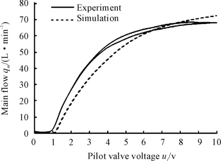
Fig.4 Characteristic curve of valve flow for Δp=2 MPa

Fig.5 Step response for Δp=2 MPa
4 The influence of underlap on performance of valve spool


Fig.6Responseofmainvalvewhenxi=0.1mm

Fig.7Responseofmainvalvewhenxi=0.4mm
AsshowninFig.8,themainvalveunderlapissetat0mm,thepilotvalvevoltageiszerobetween0to0.1s,anda2Vvoltageisappliedtopilotvalveat0.1s;fromtheFig.8,itcanbeseenthatthemainvalvealwaysowna0.07mmdisplacementwhenthepilotvalvevoltageiszero.Sotheremustexistaunderlapforfeedbacknarrowgroovetomaketheoilinletchamberconnecttothemainvalvesuperiorchamber,meanwhilethepressureofmainvalvesuperiorchamberisequaltotheinletpressureandtheareaofsuperiorchamberistwicegreaterthanthatofinferiorchamber,andthevalveclosesundertheareadifference.

Fig.8Responseofmainvalvewhenxi=0mm
The increase of underlap will ensure the stability at the small opening condition, but it will lead to the dead zone and poor linearity. And the underlap is larger, the dead zone will be larger. Fig.8, 9 shows valve spool displacement and flow characteristics when the underlaps are 0.2 mm and 0.4 mm and the pressure differential between inlet and outlet is 3 MPa. It can be seen from the simulation results that the valve spool dead zone reduces from 10% to 5% when the underlap gets reduced from 0.4 mm to 0.2 mm.

Fig.9 Characteristic curve of valve displacement in different underlap for Δp=3 MPa

Fig.10 Characteristic curve of main valve flow in different underlap for Δp=3 MPa
As shown in Fig.9. Dashed line and solid line are the flow characteristics when the underlap are 0.2 mm and 0.4 mm, respectively, and the simulation results show that the increase of underlap will lead to the decrease of linearity and current capacity. It is consistent with those of theoretical analysis.
5 Conclusions
Underlap of valve valvistor was studied by using the simulation model, and the simulation results are consistent with those of theoretical analysis, based on the experimental and simulation results, the following conclusions could be drawn.
1) In order to increase the stability of valve core and make the main valve close completely when the pilot valve is zero, the underlap of valvistor valve must be increased.
2) If the underlap is larger, the dead zone will be larger and main valve linearity and flow ability will get worse.
3) If the underlap is larger, main valve core displacement will be smaller, namely the amount of the main valve stroke will be decreased.
Acknowledgement
This paper is supported by National Natural Science Foundation of China (No. 51175362, No. 51205271) and Specialized Research Fund for the Doctoral Program of Higher Education (No. 20121402120002).
[1]Eriksson B,Andersson B R,Palmberg J O.The dynamic properties of a poppet type hydraulic flow amplifier[C]//Proceedings of the 10th Scandinavian International Conference on Fluid Power, SICFP’07,May 21-23,2007,Tampere University of Technology,Tampere,Finland,2007:161-178.
[2]Eriksson B, Andersson B, Palmberg J O. The Dynamic Performance of a Pilot Stage in the Poppet Type Hydraulic Flow Amplifier[C]//The 51st NCFP Technical Conference, 2008. Proceedings of the 51st NCFP Technical Conference: Omnipress, 2008:659-668.
[3]Quan L, Xu XQ, Yan Z, et al. A New Kind of Pilot Controlled Proportional Direction Valve with Internal Flow Feedback[J]. Chinese Journal of Mechanical Engineering, 2010, 01:60-65.
[4]Wang S F, Zhao H, Quan L. Simulation of the Dynamic Characteristics for a New Type Proportional Direction Valve[J].Hydraulics Pneumatics & Seals, 2013 (6): 35-39.
[5]Eriksson B, Larsson J, Palmberg J O. A novel valve concept including the valvistor poppet valve[C]//The Tenth Scandinavian International Conference on Fluid Power. Tampere, Finland: Tampere University of Technology, 2007:438-444.
[6]Pang J F, Quan L, Jin ZF. Characteristics Research of Cartridge Electrical Closed-loop Proportional Throttle Valve[J]. Fluid Power Transmission &Control, 2011, 3: 10-13.
10.3969/j.issn.1001-3881.2015.24.003 Document code: A
TH137.5
插装式流量放大阀反馈槽预开量对其性能的影响
郭晓霞1,马彦伟2,张勇1,黄家海1,2*,权龙1
1.太原理工大学 新型传感器与智能控制教育部与山西省重点实验室, 太原030024 2.太重榆次液压工业有限公司技术中心, 山西 榆次030600
基于流量反馈原理的Valvistor插装阀具有低泄漏、通流能力强、结构简单等优点,已被广泛应用于液压系统中,主阀反馈槽预开量对其通流能力及静态性能有显著影响。使用SimulationX建立了16通径Valvistor阀的仿真模型,通过实验验证了仿真模型的正确性,详细研究了反馈窄槽预开口量对阀芯性能的影响,结果表明:为了提高阀芯稳定性及使阀芯关闭,主阀反馈槽必须增加预开口量,但预开口量的增加会导致阀芯出现死区,同时降低了阀芯通流能力,研究结果为Valvistor阀性能的进一步提高提供了依据。
插装阀;流量放大阀;反馈窄槽预开口
1 September 2014; revised 22 December 2014;
Jia-hai HUANG, Associate Professor.
E-mail:huangjiahai@tyut.edu.cn
accepted 6 March 2015
Xiao-xia GUO, Master, Major research direction is hydraulic valve fluid simulation analysis
Hydromechatronics Engineering
http://jdy.qks.cqut.edu.cn
E-mail: jdygcyw@126.com
猜你喜欢
疯狂英语·初中天地(2022年8期)2022-08-29
能源工程(2021年6期)2022-01-06
能源工程(2021年3期)2021-08-05
水电站机电技术(2020年3期)2020-04-28
现代营销(创富信息版)(2018年6期)2018-09-05
人间(2015年16期)2015-12-30
筑路机械与施工机械化(2015年1期)2015-09-18
浙江大学学报(工学版)(2015年2期)2015-05-30
液压与气动(2015年2期)2015-04-16
机电信息(2015年3期)2015-02-27

- 机床与液压的其它文章
- Molecular dynamics study of the effects of tool geometric parameters on titanium nanometric cutting
- Research on active suspension control strategy based on fuzzy PID control
- The design of control system applied in artificial grass tufting machine adopting servomotors
- Co-simulation and consumption analysis of wheel loader on negative loading condition
- Comprehensive reliability evaluation of foreign high-end gantry machining Center
- Analysis of contact stress on interference fitted surface of the train axle-bearing