
Design and simulation of the hardware in the loop simulation platform for vehicle ACC system
2015-11-03 07:02DaoningFENGZhaoduLIUGuochengMABaofengWANG
机床与液压 2015年3期
Dao-ning FENG, Zhao-du LIU, Guo-cheng MA, Bao-feng WANG
(1School of Mechanical Engineering, Beijing Institute of Technology, Beijing 100081, China)(2Guangxi Technological College of Machinery and Electricity, Nanning 530007, China)
Design and simulation of the hardware in the loop simulation platform for vehicle ACC system
Dao-ning FENG1,2*, Zhao-du LIU1, Guo-cheng MA1, Bao-feng WANG1
(1School of Mechanical Engineering, Beijing Institute of Technology, Beijing 100081, China)(2Guangxi Technological College of Machinery and Electricity, Nanning 530007, China)
To improve the simulation accuracy for adaptive cruise control (ACC) system, the hardware in the loop simulation (HILS) platform with real actuators of ACC is developed in this paper. The HILS platform consists of simulation model parts running in the simulation instrument and hardware parts including the electronic throttle and active braking system. In the simulation model, radar simulator, controller of ACC and vehicle mode are developedin order to generate the traffic information, the control command of ACC system and calculate the motion of vehicle. By using the desired control values transmitted from the ACC’s controller, the hardware parts could realize throttle openness and braking pressure tracking control. The simulation experiments of ACC are carried out based on this HILS platform, and the simulation results confirm that the HILS platform could work in a proper way and could be used as a simulation platform to develop the controller of ACC.
Hardware in the loop simulation, Adaptive cruise control, Vehicle model, Throttle openness control, Braking pressure control
1 Introduction
Feature with speed tracking ability to the preceding vehicle, adaptive cruise control (ACC) system has become a prevailing part of comfort and safety control for modern vehicles toreduce the work load of driver and decrease the possibility of rear-head accident [1-2]. With the relative speed and distance information from the car radar, ACC vehicle could cruise at a preset speed when there is no preceding vehicle or to tracking the preceding vehicle’s speed with a safety distance when the preceding vehicle travels slower than the host vehicle’s preset speed [3-4].
Simulation experiments,which are often applied in the first steps to develop the ACC’s controller as simulator, could mimic the traffic environment and host vehicle with low cost meanwhile avoiding the risk of vehicle collision in real traffic. Generally, researchers use only mathematical models which are calculated by a computer to evaluate the performance of the ACC’s controller [5-7]. Although this method is simple and practical, the validity of experiment depends highly on the accuracy of mathematical models. In addition, simulation would get lower reliability when the key ACC actuators are difficulty to get their accurate models due to some non-linear or hysteresis characteristics. In order to solve the issue of model accuracy, some researchers use the whole vehicle on a dynamometer with audio-visual system to simulate the road environment [8-10], unfortunately it is not economic way to develop the ACC’s controller. Therefore, the hardware in the loop simulation (HILS) platform, which merely uses the hardware actuators and its sensors to improve the simulation accuracy, is a better solution for the simulation of the ACC’s controller.
In this paper, a HILS platform is designed which consists of simulation model parts and hardware parts. After elaborate the function and configuration of each module, we conduct simulation experiments of the ACC’s control. The simulation results indicate that the HILS platform could operate properly and is capable to be used in the evaluation for further improved ACC’s controllers.
2 Configuration of HILS platform
The configuration of the HILS platform is illustrated in Fig.1.
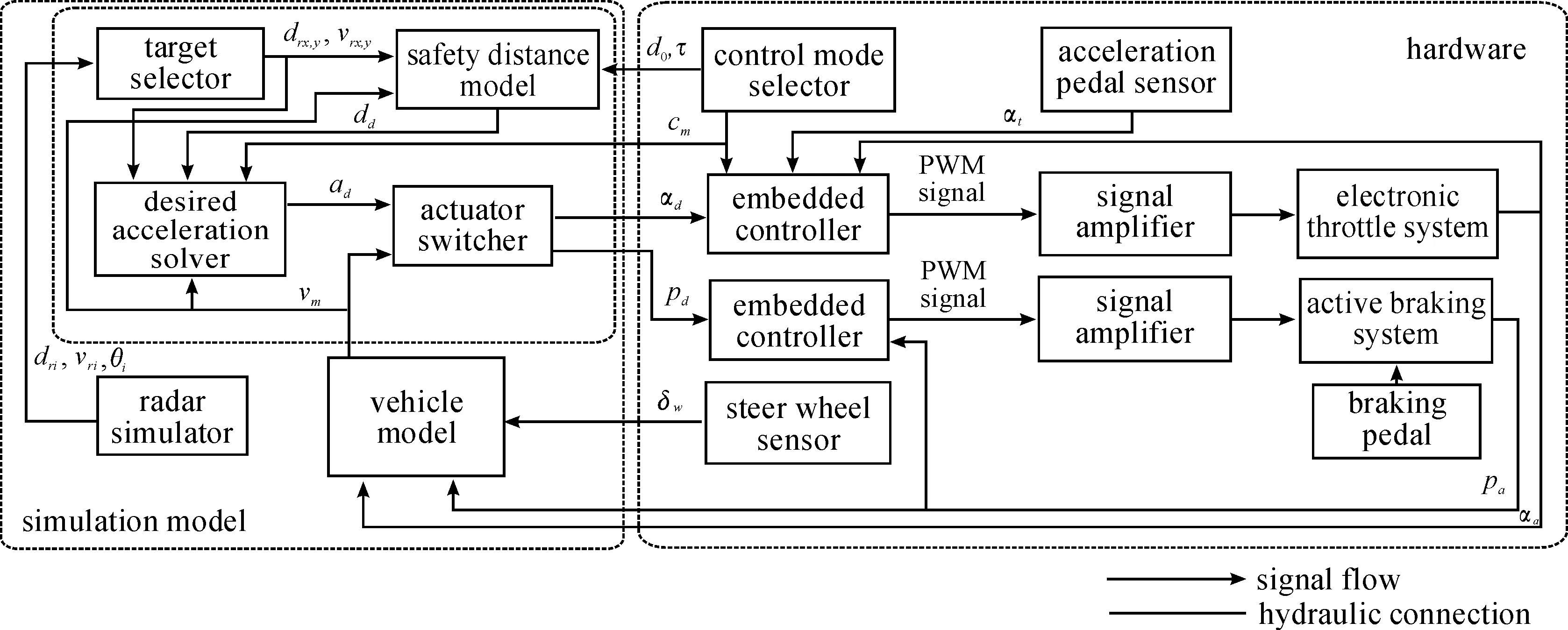
Fig.1 Block diagram of the HILS platform
The simulation model parts, which run in the dSAPE simulation instrument with the adjustable parameters, consist of radar simulator, ACC’s controller and vehicle model. Hardware uses spare parts of the controlled vehicle, including the electronic throttle system, active braking system together with their sensors and embedded controllers. Through this way, the accuracy of the simulation could be ensured. Meanwhile, driver’s action could be introduced into the simulation process to take account the driver’s reaction in the simulation experiments.
Serial communication is used to deliver the information such as desired throttle openness αdand desired braking pressure pdfrom the simulation model parts to the hardware part. Conversely, A/D convectors and I/O ports in the dSAPE instrument are used to get the signal of the actual throttle opennessαa, actual braking pressure pa, angle of steer wheel δ and other information from the hardware parts to the simulation model parts [11-12].
3 Design of simulation models
Two aspects need to be considered when the simulation modelis established, one is the model should be accurate enough to simulate the real vehicle,the other is these models should not be too complicated in terms of computation efficiencyof real time simulation.
3.1 Radar simulator
Radar simulator aims to generate the relative distance dr, relative velocity vrand the azimuth θ of the road vehicles and obstacles in the radar detectable area as the real radar works. Thus, traffic vehicle information we set in the simulation model needs to be transformed to the radar signal by using Eqs.(1)-(3).
Where, t is the simulation time, s; dxand dyare the initial relative distance inxand y direction to the host vehicle, m; vxistheinitialvelocityoftargetvehicleinxdirection,m/s;vyisthevelocityoftargetvehicleinydirection,m/s;vxhandvyhisthexandydirectionvelocityofhostvehicle,m/s;axisthexdirectionaccelerationoftargetvehicle,m·s-2;subscriptiindicatestheroadvehicle/obstaclenumber.Theroadvehicles’positionandvelocitycouldbecontrolledthroughdisplayinginterface(section2.4)atanytimeofthesimulationprocess.Besides,bandwidthnoiseisaddedtotheoutputsignalofradarsimulatortosimulatethenoisecausedbyvehiclevibrationduringtheperiodoftheuseforrealradar.
3.2 ACC’s controller
TheACC’scontrollerisdesignedwithahierarchicalstructurewhichconsistsoftargetselector,safetydistancemodel,adesiredaccelerationsolverandanactuatorswitcherasshowninFig.1.
Targetselectoraimsattrackingtheprecedingvehicle’smotionfromtheradarsignal.First,thevalidareawillbecalculatedtodecidethesearchingareaforprecedingvehicleby
(4)
Where,dminanddmaxaretheboundaries,m.Thus,onlythevehiclesinthehostvehicle’slanewouldbesearchedfor.Next,byusingthepredictedrelativedistanceandspeedcalculatedbyradarinformationofpreviouscontrolperiod,thevalidityofthetargetvehicleswouldbechecked.Thevalidityincreasesiftheradarinformationofcurrentcontrolperiodisinaccordancewiththepredictedones,orthevaliditydecreases.Inordertokeepthetargetvehicle’sinformationcontinuouslyandavoidtheaccidentalfailurefordetection,onlythetargetwhosevalidityishigherthanthecriterionwillbeacceptedasavalidatetarget.Afterthat,thevalidatetargetwhichhastheshortestlongitudinaldistancetohostvehiclewouldbeselectedastheprecedingvehicle.
Constanttimeheadisusedinsafetydistancemodelasitcouldeffectivelyrepresentthedriver’sdesiredsafetydistanceincarfollowingmaneuverinrealtraffic.Desiredsafetydistancecouldbeevaluatedasfollows:
(5)
Where,ddisthedesiredsafetydistance,m;τisthetimeconstant,s;visprecedingvehiclespeedinacarfollowingscenarioorhostvehiclespeedwhentheprecedingvehicledoesnotexist,m·s-1;d0istheminimumclearance,m.
Thedesiredaccelerationsolverusesthedistanceerrorandvelocityerrortocalculatethedesiredacceleration
(6)
(7)
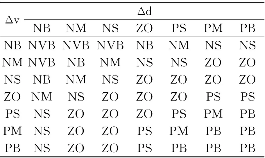
Where,Δdisthedistanceerror,m;Δvisvelocityerror,km·h-1.Consideringthehumandriver’sbehaviorinusingthetwoerrorsasinputtodeterminehostvehicle’sactioninacarfollowingmaneuver,wedesignedafuzzycontrollerfordesiredaccelerationadsolving.Inputandoutputmembershipfunctions,fuzzyrulesandtheoutputsurfaceareshowninFig.2,Tabel1andFig.3,respectively.
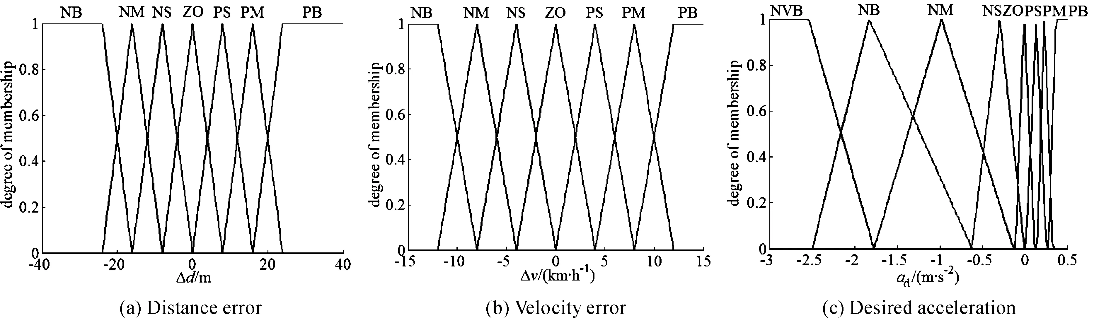
Fig.2 Membership functions of the input and output values
Sinceair drag could change dramatically with the host vehicle velocity vh, actuator switcher uses both adand vhto decide whether to use electronic throttle or active braking as actuator. To avoid frequent switch from two actuators around the switch boundary, a transition zone is designedwhere no actuator will be selected to work. The switching logic is illustrated in Fig.4, with actuator mode 0 stands for throttle, 1 for transition and 2 for braking. After that, actuator switcher would output αdor pdto the hardware actuators.
Table 1 Fuzzy rules of the desired acceleration solver
ΔvΔdNBNMNSZOPSPMPBNBNVBNVBNVBNBNMNSNSNMNVBNBNMNSNSZOZONSNBNMNSZOZOZOZOZONMNSZOZOZOPSPSPSNSZOZOZOPSPMPBPMNSZOZOPSPMPBPBPBNSZOZOPSPBPBPB
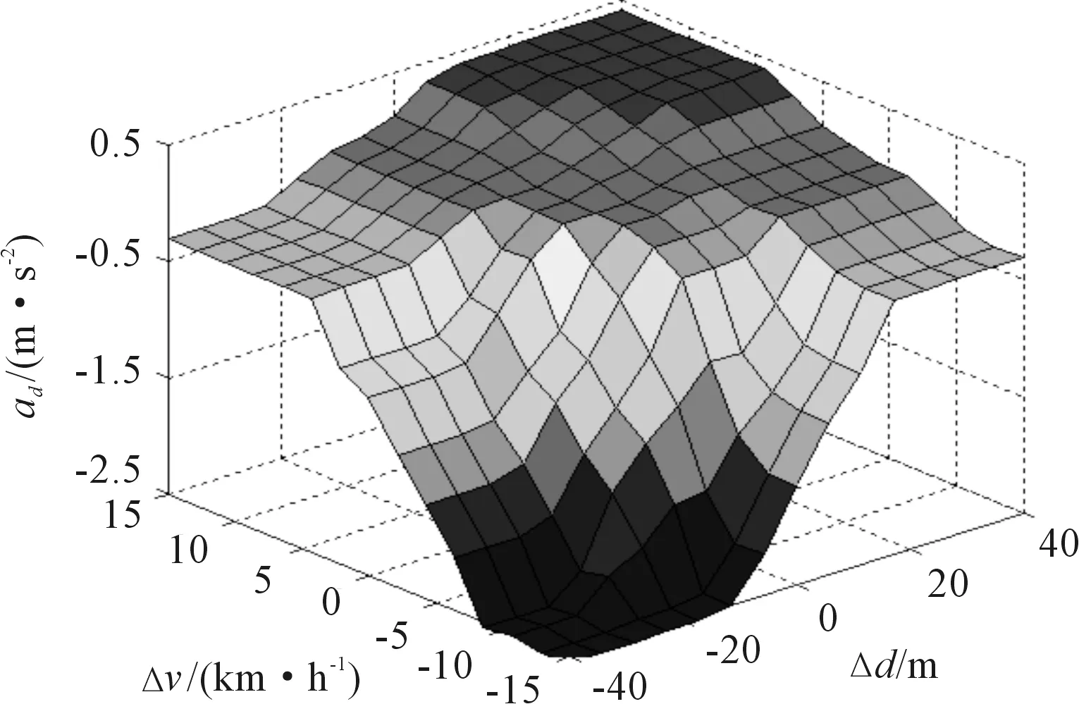
Fig.3 Output surface of the fuzzy controller
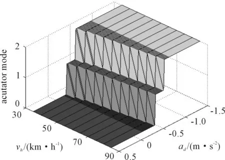
Fig.4 Switching logic for actuators
3.3 Vehicle model
Consider the requirements for ACC’s simulationscenarios, a 7 DOF vehicle model is built with the independent variables are longitudinal vehicle speed Vx, lateral vehicle speed Vy, yaw rate ψ, and the rolling speed of the four wheels ωfl,ωfr, ωrl, ωrr.Assumethevehicledriversonaflatroadandignoretherollingresistance,wecouldobtainthefollowingvehicledynamicequationsaccordingtoFig.5.
(8)
(9)
Where, m is the mass of vehicle, kg; δ is the steering angle of front wheels, rad; Fwis the air drag, N; Izis the vehicle rotational inertia ofzaxis, kg·m2; Iwis the rotational inertia of the wheel and its accessories, kg·m2; a and b are the horizontal distance from the mass center to the front and rear wheel axis respectively, m; c is the wheel base, m; reis the effective rolling radius, m. F is the road force in corresponding direction of the wheels [13], N; Tais driving torque obtained from throttle openness and engine speed, N·m; Tbis the braking torque obtained from braking pressure of each wheel. Subscription fl, fr, rl, rr denote front left, front right, rear left, rear right wheel, and x, y denote x, y direction.
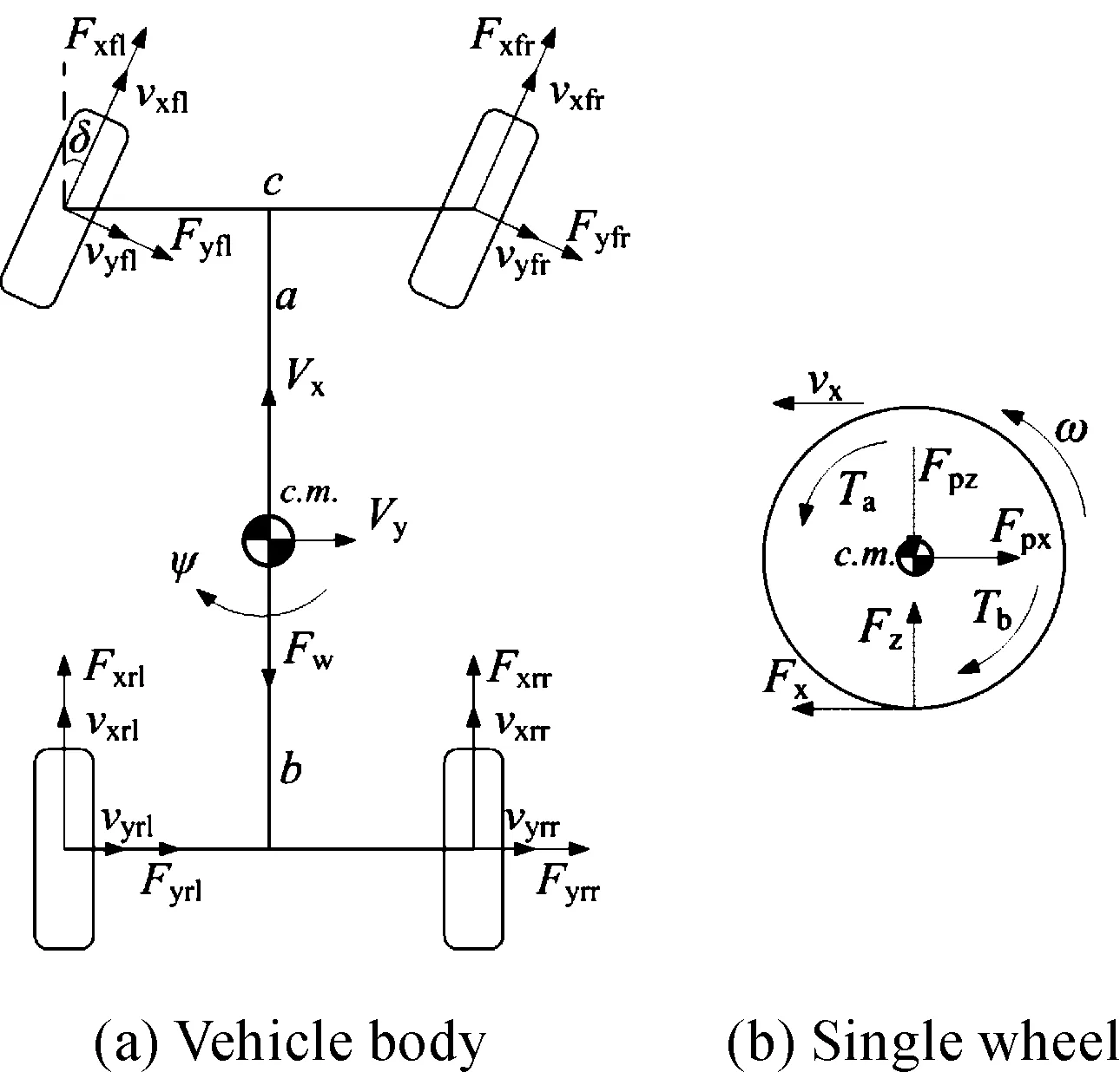
Fig.5 Vehicle dynamics model
Since Magic tire combined slip model would both consider longitudinal and lateral slip to generate tire fore, it would get better accuracyfor ACC’s simulation on a curvature road. Magic tire model could be represent by
(13)
(14)
Where, fx, fyare non-lineal functions; vx, vyare the velocity of wheel in itsxandydirection, m·s-1; Fzis the vertical load of the wheel, N; μ is the friction coefficient of the road. Furthermore, according to Fig.5, vxx, vy, Fzcould beevaluated as follows:
(15)
(16)
(17)
(18)
(19)
(20)
Where,l is the wheel base, m; hgis the height of the mass center, m.By using Eqs.(8)-(20), the vehicle’s motion could be determined by the numerical calculation in simulation model.
3.4 Displaying interfaces
Displaying interfaces could directly monitoring the control signals and change the simulation parameters, thus 3 displaying interfaces are designed to achieve different displaying functions as illustrated in Fig.6.
Road traffic displaying interface displays the entire road vehicles’ relative position to host vehicle, meanwhile these vehicles’ motion could be controlled by using the input box of the displaying interface. Information typically could be obtained from the dashboard of real vehicle including the vehicle speed, engine speed and the control status are shown in the host vehicle displaying interface. All other key variables like dd, dr, Δd, vh, vr, Δv are displayed and saved in the experimental displaying interface.
4 Control of hardware actuators
As illustrated in Fig.1, we use embedded controller togenerate the control signals to manage actual throttle openness and active braking pressure to track with their desired values. For electronic throttle control, as a torque motor is used for throttle’s action, a feed forward and PID feedback controller is designed for the trackingof throttle openness. For active braking pressure’s control, we used a modified PID controller to improve control results in our previous work[14-16]. The control results of throttle openness and braking pressure are shown in Fig.7 and Fig.8 with desired values are step, ramp and sine signal, respectively.
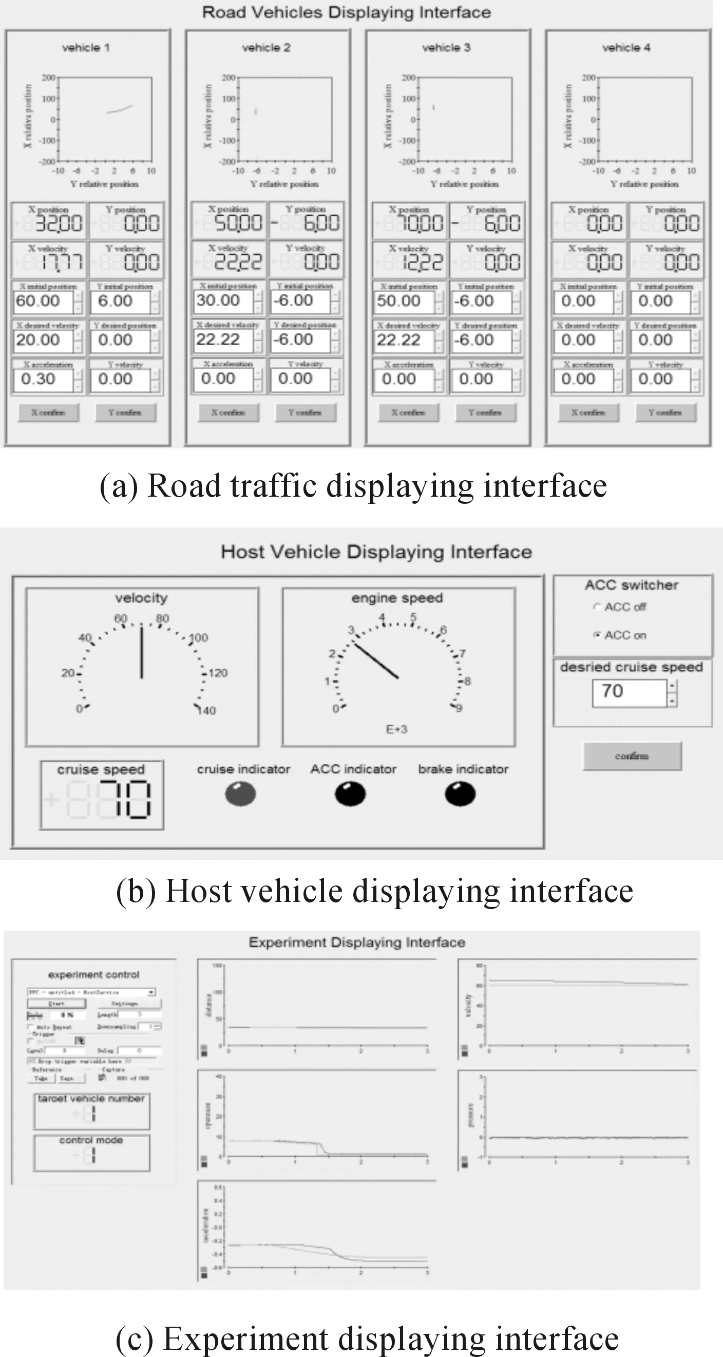
Fig.6 Displaying interfaces
5 Simulations results
Based on the HILS platform, simulation experiments of 3 typical ACC maneuver are conducted to check the functionality of simulator. The simulation results are shown in Fig.9, where these diagrams are the actual distance between the two vehicles and the safety distance, host vehicle velocity and target vehicle velocity, actual and desired throttle openness, actual and desired braking pressure from top to bottom respectively in each figure.
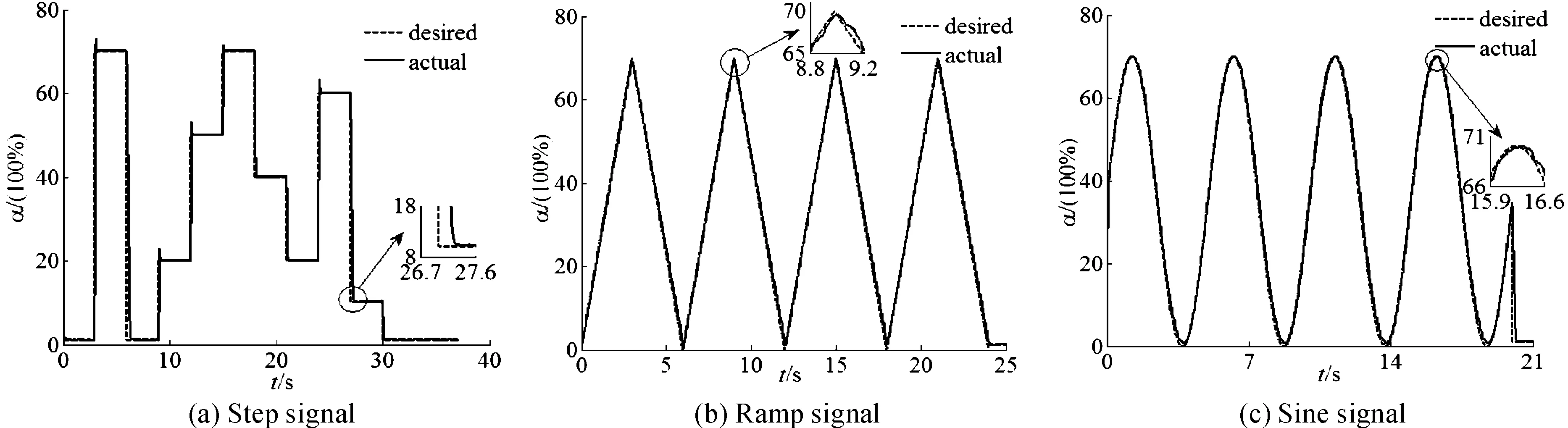
Fig.7 Control results of different desired throttle openness
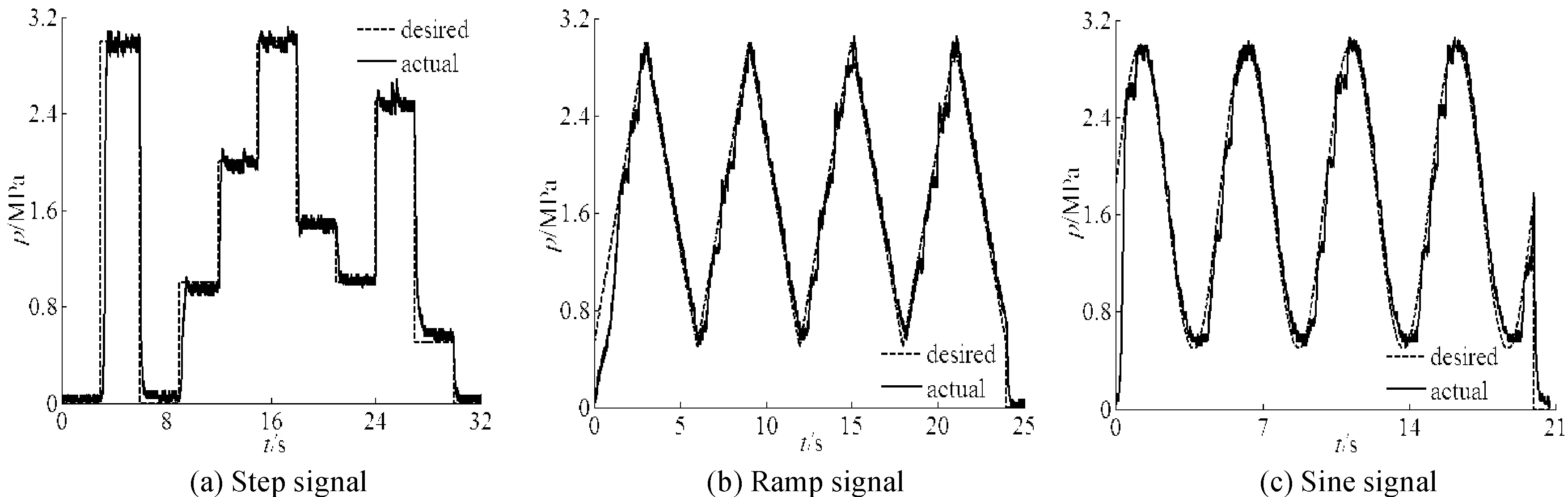
Fig.8 Control results of different desired braking pressure
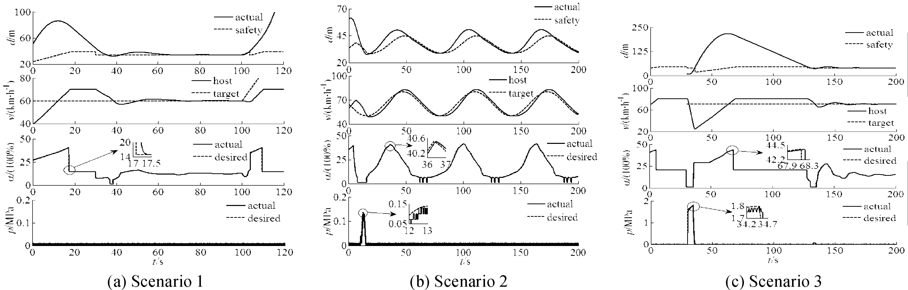
Fig.9 Simulation results of the HILS
In the first scenario, the cruise speed of host vehicle is set to 70 km/h while the preceding vehicle travels at a constant velocity of 60 km/h in the same lane of the host vehicle with an initial distance of 50 m between them. Initially, as the actual distance is greaterthan the safety distance, host vehicle will cruise at the speed of 70 km/h. At about 30 s, preceding vehicle is identified due to the smaller relative distance, and the motion of host vehicle is controlled through throttle action to track the safety distance and the velocity of preceding vehicle. At 100 s, the target vehicle begins to accelerate and drive away, thus the host vehicle come back to the state of cruising at 70 km/h.
The speed of preceding vehicle is changed in a sine form from 50 km/h to 80 km/h in host vehicle’s lane in the second scenario. In this case, the rapid and accurate response of the hardware actuators becomes crucial for the host vehicle to tack the dynamic safety distance and the speed of preceding vehicle. From Fig.9 (b), one could conclude the host vehicle tracks preceding vehicle’s motion in a good way and the control errors do not diverge.
The sudden cut-in maneuver of adjacent lane vehicle is simulated in scenario 3. The target vehicle cutinto host vehicle’s lane at the speed of 70 km/h with a relative distance of 10 m while the host vehicle cruises at 80 km/h. Since the actual distance is far less than the safety distance, active braking is applied to exert greatdeceleration. After obtainingthe safety distance, the host vehicle switch to the cruise mode and eventually tracks with the safety distance and the speed of preceding vehicle.
6 Conclusions
Based on the above results, one could conclude that the HILS platform could function properly with an effective communication between the model parts and the hardware parts. High accuracy could be achieved in the throttle openness and braking pressure tracking control. Meanwhile, the controller designed in section 2.2 could realize satisfied control results in different traffic scenarios for ACC system. Furthermore, performance evaluation could be obtained for other improved or original ACC controller by using this HILS platform. Through the change of corresponding controller andthe vehicle model in the software, this platform could also be used in the HILS simulation for other active safety control algorithm.
Acknowledgements
This paper is supported by General equipment department “Five-Year” advanced research projects of China(40401040302)
[1]Xiao Lingyun, Gao Feng. A comprehensive review of the development of adaptive cruise control systems[J]. Vehicle system dynamics, 2010, 48(10):1167-1192.
[2]Zhou J, Peng H. Range policy of adaptive cruise control vehicle for improved flow stability and string stability[J]. IEEE transactions on intelligent transportation systems, 2005, 6(2):229-237.
[3]Seungwuk M, Wanki C, Kyongsu Y. Intelligent vehicle safety control strategy in various driving situations[J]. Vehicle system dynamics, 2010, 48(1):537-554.
[4]Seungwuk M,Hyoungjin K, Kyongsu Y. Multi vehicle target selection for adaptive cruise control[J]. Vehicle system dynamics, 2010, 48(11):1325-1343.
[5]Liu Hong, Gong Lilong. Study on adaptive cruise control spacing policy and stability analysis[C]// 2011 international conference on electric information and control engineering, April 15th-17th, 2011, Wuhan, 2011:5364-5367.
[6]Asadi B, Vahidi A. Predictive cruise control: utilizing upcoming traffic signal information for improving fuel economy and reducing trip time[J]. IEEE transactions on control systems technology, 2011,19(3):707-714.
[7]Zhai Yao, Li Lingxi, Widmann G R, et al. Design of switching strategy for adaptive cruise control under string stability constraints[C]// American Control Conference, June 29th-July 1st, 2011, San Francisco, CA, 2011:3344-3349.
[8]Verburg D J, Vanderknaap A C M, Ploeg J. VEHIL developing and testing intelligent vehicles[C]// IEEE intelligent vehicles symposium, 2002, Versailles, 2002:537-544.
[9]Jihua Huang, Tan H S. A low-order DGPS-based vehicle positioning system under urbanenvironment[J]. IEEE/ASME transactions on mechatronics, 2006, 11(5): 567-575.
[10]Kyongsu Y, Donghoon H. A vehicle stop and go control strategy based on human drivers driving characteristics[J]. Journal of mechanical science and technology, 2005, 19(4): 993-1000.
[11]Feng Daoning, Liu Zhaodu, Pei Xiaofei, et al. Precise electric throttle openness control for vehicle ACC system[J]. Journal of Beijing Institute of Technology, 2011, 31(5):528-532.
[12]Obradovic D, Lenz H, Schupfner M. Fusion of map and sensor data in a modern car navigation system[J]. Journal of VLSI signal processing systems for signal image and video technology, 2006, 45(1-2): 111-122.
[13]Feng Daoning, Ye Yang, Zhang Biao,et al. Research and application of body deceleration in ABS road condition identification technique[J]. Journal of Kunming University ofScience and Technology, 2010, (6):56-60.
[14]Pei Xiaofei, Liu Zhaodu, Qi Zhiguo, et al.Development of in-vehicle expterimental platform for ABS/ASR/ACC integrated system[J].Journal of Wuhan University of Technology,2011, 35(6):500-504.
[15]Ma Guocheng, Liu Zhaodu, Pei Xiaofei, et al. Design of the pressure regulation algorithm for active braking in vehicle ACC system[J]. Journal of Beijing Institute of Technology, 2011, 20(4):20-27.
[16]Zhang Dezhao, WANG Jianqiang, et al.Switching strategy for adaptive cruise control Modes for continuous acceleration[J]. Journal of Tsinghua University(Science and Technology),2010,50(8):1277-1281.
汽车自适应巡航控制系统硬件在环仿真平台的设计与仿真试验
冯道宁1,2*,刘昭度1,马国成1,王宝峰1
1.北京理工大学 机械与车辆工程学院,北京100081 2.广西机电职业技术学院 电气工程学院,南宁530007
为了提高自适应巡航控制(ACC)系统的仿真精度,利用实车ACC系统的执行机构建立了硬件在环仿真(HILS)平台。HILS平台由仿真模型和硬件部分组成。仿真模型将运行在dSPACE仿真系统中,包括为了产生雷达模拟信号、ACC控制指令及计算车辆运行状态的雷达模拟器、ACC控制器和车辆模型。硬件部分主要包括电子节气门系统、主动制动系统及其附属的传感器及控制器等。通过串口通信接收来自ACC控制器的指令,HILS平台的硬件可以完成节气门开度和制动压力跟随控制。利用HILS平台进行了不同工况下的ACC仿真试验,仿真结果表明:HILS平台工作状况良好,并可以用于ACC控制器的开发。
硬件在环仿真;自适应巡航控制;车辆模型;节气门开度控制;制动压力控制
1 September 2014; Revised 22 December 2014;accepted 6 March 2015
Dao-ning FENG, Associate professor,
Ph.D., Candidate, E-mail: fdn1978@126.com
10.3969/j.issn.1001-3881.2015.18.001 Document code: A
U467.1
Hydromechatronics Engineering
http://jdy.qks.cqut.edu.cn
E-mail: jdygcyw@126.com
猜你喜欢
中国机械工程(2022年22期)2022-11-25
中国机械工程(2022年7期)2022-04-20
科学与财富(2021年33期)2021-05-10
北京汽车(2021年2期)2021-05-07
电站辅机(2021年4期)2021-03-29
中国机械工程(2019年17期)2019-09-19
汽车维护与修理(2019年3期)2019-08-08
汽车维护与修理(2018年19期)2018-04-28
中国机械工程(2018年4期)2018-03-06
汽车维修与保养(2015年1期)2015-04-17
- 机床与液压的其它文章
- Numerical simulation on the aerodynamic performance of ice coating airfoil of wind turbine blade
- The design of the hydraulic cylinder test bed based on cartridge valves
- Research on flexible manufacturing system real-time scheduling optimization
- Mathematic modeling method for addendum line of spiral bevel Gear
- A research on film thickness of a typical dynamic seal for hydraulic actuators
- Manufacturing of self-lubricating diamond tools with Ni-Cr alloy adding with Ni/C