
Frequency-SPeed Control Model Identification of Ultrasonic Motor Using SteP ResPonse
2015-11-24 02:39ShiJingzhuo史敬灼ZhangCaixia张彩霞
关键词:彩霞
Shi Jingzhuo(史敬灼)'Zhang Caixia(张彩霞)
College of Electrical Engineering'Henan University of Science and Technology'Luoyang 471023'P.R.China
Frequency-SPeed Control Model Identification of Ultrasonic Motor Using SteP ResPonse
Shi Jingzhuo(史敬灼)*'Zhang Caixia(张彩霞)
College of Electrical Engineering'Henan University of Science and Technology'Luoyang 471023'P.R.China
Control model of ultrasonic motor is the foundation for high control performance.The frequency of driving voltage is commonly used as control variable in the speed control system of ultrasonic motor.Speed control model with the input frequency can significantly improve speed control performance.Step response of rotating speed is tested.Then'the transfer function model is identified through characteristic point method.Considering time-varying characteristics of the model parameters'the variables are fitted with frequency and speed as the independent variables'and the variable model of ultrasonic motor system is obtained'with consideration of the nonlinearity of ultrasonic motor system.The proposed model can be used in the design and analysis of the speed control system in ultrasonic motor.
ultrasonic motor(USM);speed control;characteristic point method
0 Introduction
Ultrasonic motor(USM)is a kind of special motor'and it uses the inverse piezoelectric effect of the piezoelectric material to make the stator generate mechanical vibration within the ultrasonic frequency band.The rotor is driven through the friction between the stator and the rotor[1-4]. USM contains a series of nonlinear processes such as piezoelectric energy conversion'friction energy transfer'and so on'so it is nonlinear'time-varying and strong coupling.Therefore'it is difficult to realize high-precision motion control.
The mathematical model of the control object is an important foundation of the control system analysis'design and performance evaluation. More reasonable control strategies can also use the model[5-11].Eut the modeling problem of USM has not been solved mainly because of the complexity of its operation mechanism and its short research history.The existing researches mainly concentrate on theoretical modeling and numerical modeling.These methods are all based on piezoelectricity and friction theoretical knowledge'and trying to establish a model completely describing the running process of USM[12-21]. Great progress has been made'and it has become a powerful tool for the analysis and design of USM.Eut these models are too complex and difficult for direct control applications.On the other hand'since our understanding of USM′s nonlinearity is not thorough enough and the expression of it is not comprehensive'the model still has potential.
Erom the perspective of control application' the modeling of USM can also adopt other methods'e.g.system identification.The input and output signals of USM can reflect the dynamic characteristics of the motor system'and if we can select the appropriate form of the input signal' the input and the output signals can completely contain the non-linear characteristics of USM which we concern[2'3'13].Therefore'we can usethe input and the output data obtained from the test to simulate the model of USM.And the model can be directly applied to control.
Speed control is the core of motor motion control.In the USM speed control'frequency of the driving voltage is often used as a control variable to regulate speed.The speed control model with an input frequency can significantly improve speed control performance.We adopt the identification modeling method to establish the speed control model of USM which appropriately contains nonlinear characteristics.
1 Design of Data Test
We intend to establish the frequency-speed control model of USM through identification method.Therefore'we need to measure the input and the output signals in the experiments as frequency and speed'respectively.The speed of the motor is the output response at a specific frequency input signal.Adopting different forms of input signal'the output response will be different.We must adopt an appropriate form of the frequency signal as the input to make sure the measured data completely reflect the characteristics of USM.The selected input signal must be sufficient to motivate all the dynamic characteristics of USM.It means that the frequency range of the input signal should be able to cover the part that we concern in the dynamic frequency range of USM.Step input signal is a common signal meeting the above requirements.The form of step signal is simple.Eesides it is easy to achieve'analyze and research.Therefore'it is more appropriate as an input signal.In this paper'we use the frequency step signal as input'and measure the step response data of speed under open loop control of the speed to identify the model of motor.
Shinsei USR60'a two-phase traveling wave ultrasonic motor'is used as the experiment motor.And the homemade H-bridge phase-shift PWM circuit is used as drive control circuit.DC tacho-generator is coaxial rigid connection with the motor'and it is used to measure the motor′s speed.The frequency of the driving voltage is set to a desired value by adjusting the circuit.In order to ensure the accuracy of the identification' we need to obtain the exact value of actual driving frequency.In the experiment'the waveform of the motor′s driving voltage is measured in realtime'and the frequency value is obtained by processing the recorded waveform.In order to ensure the measurement data to accurately reflect the dynamic characteristics of USM'and the credibility of the motor model which is obtained by identifying'we need to confirm the parameters of input signal such as step amplitude'sampling time'length of data records according to the prior knowledge and the control performance before experiment.
Operating frequency of USM is generally larger than its mechanical resonant frequency'the higher the frequency'the lower the motor speed. If the step amplitude of frequency input is too large'and the speed is too low'the signal-tonoise ratio of the measured signal will decrease. It is not conducive to improve the accuracy of the identification.If the given frequency is too low' and the desired speed corresponding is too high' the variation of the speed of motor will be large and may suddenly stall the open-loop running USM.The operating frequency range of experimental motor is 41.5—44 k Hz.The selected step range of the frequency input is 42.3—43.3 k Hz after open-loop operation.USM has different performance characteristics under different input frequencies due to its complex nonlinearity.Therefore'we need to measure the input and the output data'respectively'under different input step frequencies in the experiment'and to sufficiently reflect the characteristics of motor.Meanwhile' considering the uncertainties and random perturbations which may occur in the testing process' we need to measure sets of data under each frequency to eliminate those obvious deviations.The seted values of the step input frequency in experiment and the corresponding steady-state speed values of the motor are shown in Table 1.
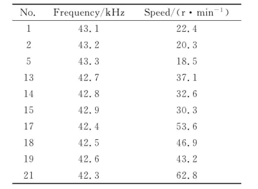
Table 1 Tested data of stePPing resPonse
The data recording time needs to be long enough to contain the complete step response process.Eut it will bring unnecessary burden to the calculation of model identification and may affect the accuracy of identification if the time is too long and data quantity is too big.The experiments show that the step response time of the experimental motor is no longer than 100 ms. Therefore'the selected data recording time is 200 ms.
In the experiment'the data recording is completed by the A/D sampling'and the sampling time directly affects the accuracy of identification. The sampling frequency should be at least twice that of the cutoff frequency of the object according to sampling theorem.If the sampling time is too large'it will cause excessive loss of information and reduce the accuracy of identification. And in the case of the same recording time'decreasing the sampling time will increase the amount of data.At the same time'because of the limitations of response speed and calculation speed of hardware'the sampling time cannot be too small.Eor the experiment motor'the required control response bandwidth is not greater than 500 Hz.And further taking into account that we need to obtain frequency information from the measured voltage waveform'the selected sampling frequency is 10 M Hz in the experiment to ensure the accuracy of measurement.
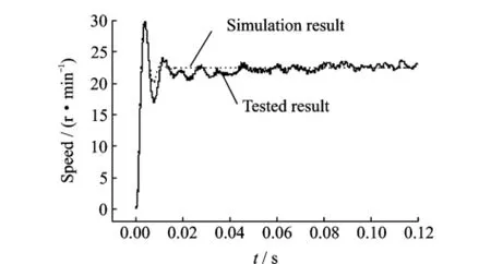
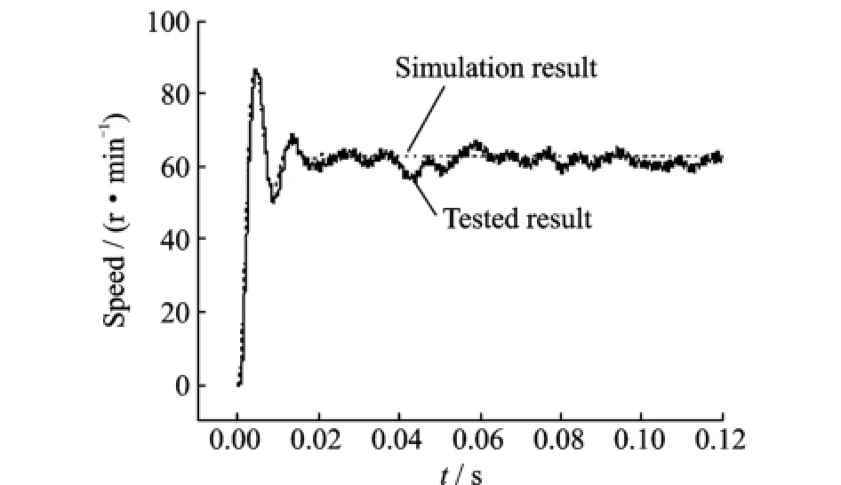
In the experiment'we collect the driving voltage of motor and tacho-generator output voltage signal synchronously'the measured step response curve is shown in Eig.1.It only shows part of the time data to make the waveform clearly visible.A four-character indent is recommended for all paragraphs except the first one that immediately follows a section title or a subsection title.
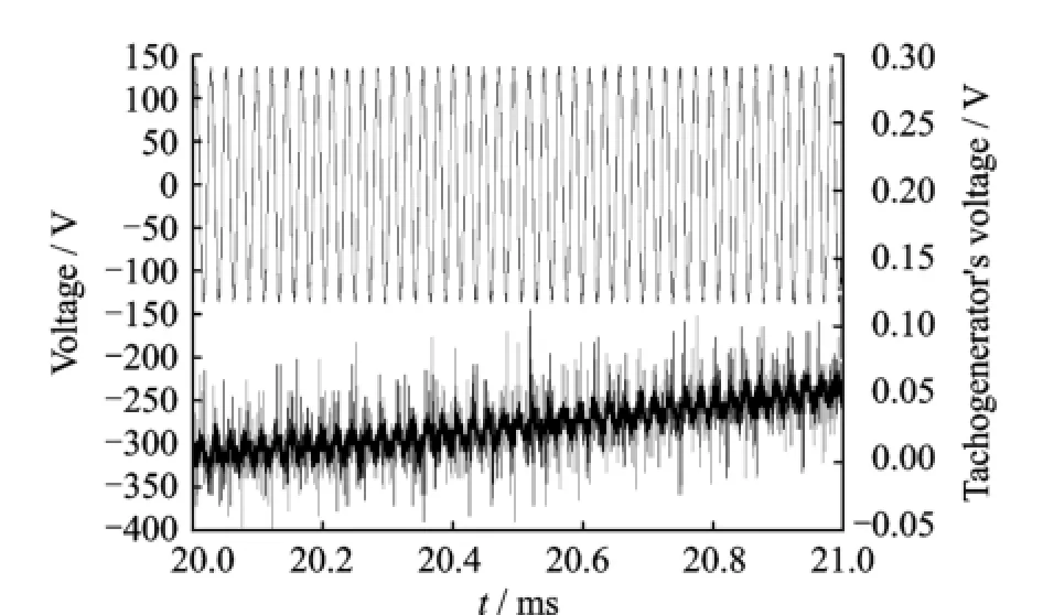
Eig.1 Tested step response
2 Model Identification of Motor Based on SteP ResPonse
We need to preprocess these data before model identification.In Eig.1'the measured data contains noise.The noise becomes more obvious when the amplitude of the tacho-generator′s output signal is small.Since the required bandwidth of the control response is not greater than 500 Hz'we take low pass filtering for the measured speed signal and the cutoff frequency of filter is 1 000 Hz.On the other hand'the start time of data recording is earlier than the action time of step input to ensure the integrity of the measurement data.Therefore'there is a section of zero speed data at the beginning of the recording data' this section is useless for identification.If we reserve those data'they would affect the accuracy of identification.Therefore'they should be deleted.Meanwhile'the DC component existing in the measurement data will also affect the accuracy of identification and can be removed using the average method.After the preprocessing'the obtained speed step response data are shown in Eig.2.These data can be used for model identification.
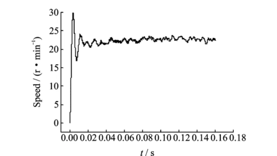
Eig.2 Step response after data pretreatment
As mentioned before'USM is a kind of nonlinear and time-varying object.In order to achieve high-performance control'the control algorithm should have the ability of online correction.It means that the control algorithm is self-adapting. Therefore'the identification motor model is selected as second-order.
There are many different methods to identify the model'such as area method'characteristic point method'etc.These methods all utilize step response data.The area method can take full advantage of data information of every point to identify the model'and have strong ability to suppress noise.Eut it is not an optimization'and it is not suitable to the specified order model.If the selected model order is equal or close to the order of the actual object'more desirable results can be obtained using the area method.Eut during the actual control system design'we often use a loworder model to simulate the high-order object to simplify the control process.Then the obtained low-order model will inevitably have a deviation and the model accuracy is not high by using the area method.Since the measured step response curve has attenuation oscillation characteristics' we can adopt characteristic point method which is specific to second-order underdamping model to identify the model of motor.
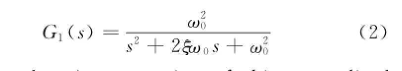
The transfer function of the frequency-speed control model of USM is set to
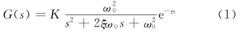
where K=h1/f'h1is the stable value of speed'f the given value of frequency step signal'andτthe delay time.K andτcan be obtained directly from the measured data.ξandω0are all model parameters to be identified'where'is the damping coefficient andthe natural frequency.Eor the convenience of identification' Eq.(1)normalizes to obtain the standard unit transfer function of the second-order underdamping model
The time domain expression of this normalized object′s step response is

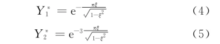
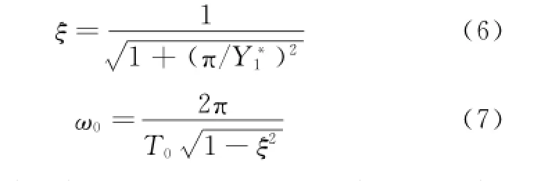
Erom Eqs.(4'5)and T0'we can obtain
Using the characteristic point method and the selected motor model of Eq.(2)to identify and calculate the measured frequency and speed data. The model parameters are shown in Table 2.

Table 2 Model Parameters identified by characteristic Point method
The frequency-speed control model of ultrasonic motor system can be obtained by putting the model parameters(shown in Table 2)into the model Eq.(2).Ey adopting this model'the step response of ultrasonic motor system can be calculated.Then the accuracy of the model can be verified by comparing the calculated response with the measured step response.Eigs.3'4 show the comparison of the two kinds of step response.In Eigs.3'4'solid line is the curve of measured step response'and dotted line is the step response which is calculated by identification model.It is thus clear that'the model reflects the main dynamic characteristics of actual system except the irregular fluctuations during the steady-state operation of motor.
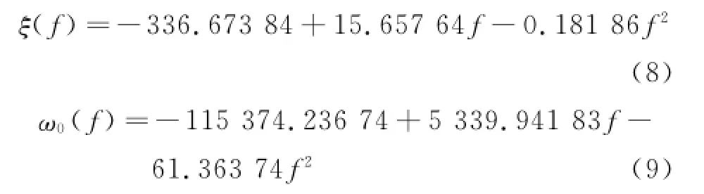
Table 2 shows that the motor model parameters are time-varying.It is caused by the nonlinearity of USM.In order to make the model fully reflect the nonlinear characteristics of motor'the time-varying characteristics of parameters need to be represented in the motor model.Since the motor shows different characteristics under different input frequencies'we can use the variation of model parameters along with the change of frequency to represent the time-varying nonlinearity.And in the control process'the given value of frequency is the output of the speed controller.If we ignore the dynamic process of frequency regulating'we can consider the given value of frequency as the actual value'so the frequency value is known.Therefore'the frequency f can be used as a variable to fit the parametersξandω0'and they are expressed withξ(f)andω0(f)'respectively.To make the fitting function be easy to calculate online by using the control chip'e.g. DSP'we choose the quadratic polynomial function to fit according to the change rule of the model parameters'and the obtained fitting function as shown in Eqs.(8'9).
Eig.3 Tested and simulated step response with n= 22.4 r/min
Eig.4 Tested and simulated step response with n= 62.8 r/min
The comparison of the before and the after fitting model step response curve is shown in Eig. 5.In Eig.5'the dashed line is the response which is obtained by calculating the fitting data.It can be seen that both coincide basically and the model fitting effect is good.The model parameter values which are calculated from the fitting function Eqs.(8'9)are shown in Table 3.In the table' the variance is between the step response data which is calculated by using fitting model and the measured data'the relative error is between the identification value of model parameters and the fitting values of model parameters.
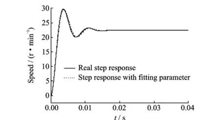
Eig.5 Step response with f as fitting parameter
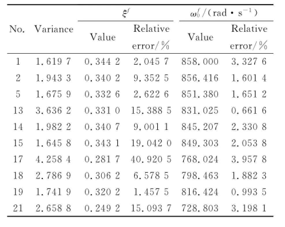
Table 3 Model Parameters fitted by frequency fitting function
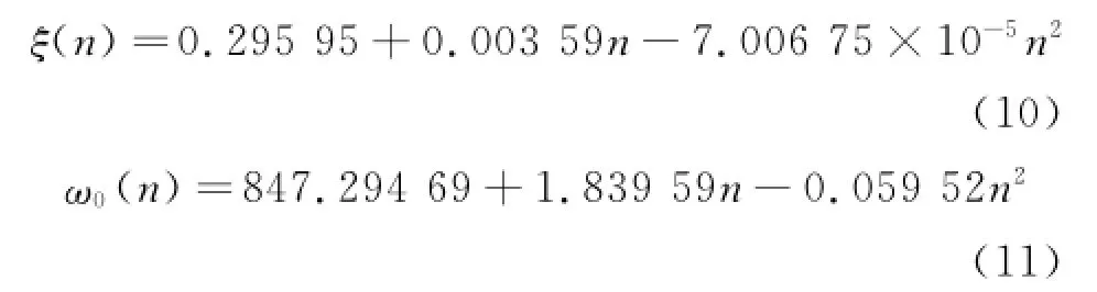
In the USM speed control system'the measured speed value is necessary to constitute the closed-loop control.Since the speed data is known'we can also use the speed n as the independent variable to fit the model parametersξand ω0'expressed withξ(n)andω0(n)'respectively. Adopting the output fitting function is likely to get better control effect for some control strategies.According to the identified model parameters'we choose the quadratic polynomial function to fitξandω0.The fitting functions are shown in Eqs.(10'11).
The comparison of the before and the after fitting model step response curve is shown in Eig.6. The model fitting parameters which adopt the speed n as the independent variable are shown in Table 4.In the table'the variance is between the step response data which is calculated by fitting model and the measured data'the relative error is between the identification value of model parameters and the fitting values of model parameters.

Eig.6 Step response with n as fitting parameter
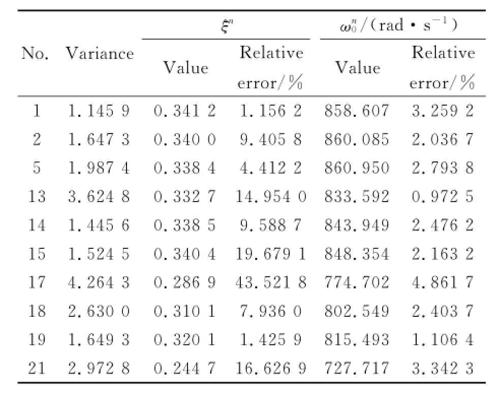
Table 4 Model Parameters fitted by sPeed fitting function
3 Conclusions
In the paper'we adopt the characteristic point method to identify the USM model according to the frequency step input data and the speed output data'the conclusions are as follows:
(1)We need to select an appropriate form of input signal to sufficiently excite characteristics of motor by using the method of system identification to model the motor.The step signal is a kind of input signal which meets the requirement of identification.
(2)Characteristic point method is a kind of identification method and it aims at the set motor model(second-order underdamped model)'and the identification effect is better.
(3)Results of identification show that the model parameters are time-varying.Therefore' the model parameters are fitted to the polynomial function with frequency and speed as independent variables'respectively.And we seek timevarying rules to properly reflect the nonlinear characteristics of the motor.It is simple to implement and results good.
Acknowledgement
This work was supported by the National Natural Science Eoundation of China(No.U1304501).
[1] Guo Mingsen'Hu Junhui'Zhu Hua'et al.Threedegree-of-freedom ultrasonic motor using a 5-mm-diameter piezoelectric ceramic tube[J].IEEE Transactions on Ultrasonics'Eerroelectrics'and Erequency Control'2013'60(7):1446-1452.
[2] Shi Jingzhuo'Zhao Eujie'Shen Xiaoxi'et al.Chaotic operation and chaos control of travelling wave ultrasonic motor[J].Ultrasonics'2013'53(6):1112-1123.
[3] Senjyu T'Nakamura M'Urasaki M'et al.Mathematical model of ultrasonic motors for speed control[C]∥IEEE'Applied Power Electronics Conference and Exposition'APEC′06.Dallas'TX'United States:IEEE'2006.
[4] Maas Jürgen.Model-based control for ultrasonic motors[J].IEEE/ASME Transactions on Mechatronics'2000'5(2):165-180.
[5] Pirrotta Simone'Sinatra Rosario'Meschini Alberto. A novel simulation model for ring type ultrasonic motor[J].Meccanica'2007'42(2):127-139.
[6] Giraud Erédéric'Semail Eetty.Analysis and phase control of a piezoelectric traveling-wave ultrasonic motor for haptic stick application[J].IEEE Transactions on Industry Applications'2004'40(6):1541-1549.
[7] Eazrafshan Eazel'Rasti Eehnood'Mojallali Hamed. Euzzy modeling and position control of a traveling wave ultrasonic motor[C]∥ICCAE'2010 The 2nd International Conference on Computer and Automation Engineering.Singapore:IEEE'2010'5:457-461.
[8] Lin E J.Euzzy adaptive model-following position control for ultrasonic motor[J].IEEE Transactions on Power Electronics'1997'12(2):261-268.
[9] Erdal Eekiroglu.Microcontroller-based full control of ultrasonic motor with frequency and voltage adjusting[J].Sensors and Actuators A:Physical'2008'141(1):151-159.
[10]Chen T C'Yu C H'Tsai M C.A new driver based on dual-mode frequency and phase control for traveling-wave type ultrasonic motor[J].Energy Conversion and Management'2008'49(10):2767-2775.
[11]Lin R J'Hwang W J'Wai R J.Ultrasonic motor servo-drive with online trained neural-network modelfollowing controller[J].IEEE Proceedings:Electric Power Applications'1998'145(2):105-110.
[12]Pigache E'Giraud E'Lemaire-Semail E.Modelling and identification of a planar standing wave ultrasonic motor[J].EPJ Applied Physics'2006'34(1):55-65.
[13]Zhang Jiantao'Zhang Tiemin'Liang Li.Nonlinear modeling and generalized predictive control of ultrasonic motor[J].Electric Machines and Control' 2011'15(6):50-56.
[14]Shi Jingzhuo'You Dongmei.Characteristic model of travelling wave ultrasonic motor[J].Ultrasonics' 2014'54(2):725-730.
[15]Zhang Xinliang'Tan Yonghong.Modelling of ultrasonic motor with dead-zone based on Hammerstein model structure[J].Journal of Zhejiang University: Science A'2008'9(1):58-64.(in Chinese)
[16]Sun Eengyan'Qu Jianjun'Wu Peilian.New visco-elastic contact model of traveling wave ultrasonic motor with stator frictional layer[J].Journal of Harbin Institute of Technology(New Series)'2007'14(5): 705-710.(in Chinese)
[17]Jung P L'Jong S R'Kyung P Y'et al.Characteristic analysis of a traveling wave ultrasonic motor using an ellipsoidal static contact model[J].Smart Materials and Structures'2009'18(11):1-10.
[18]Shi Jingzhuo'Lv Lin'Zhang Yu.Dynamic Takagi-Sugeno model for the control of ultrasonic motor[J]. Journal of Control Science and Engineering'2011' 2011:1-9.
[19]Liew Pay Jun'Shimada Keita1'Mizutani Masayoshi' et al.Eabrication of microstructures on RE-SiC by ultrasonic cavitation assisted micro-electrical discharge machining[J].International Journal of Automation Technology'2013'7(6):621-629.
[20]Qu Jianjun'Sun Eengyan'Zhao Chunsheng.Performance evaluation of traveling wave ultrasonic motor based on a model with visco-elastic friction layer on stator[J].Ultrasonics'2006'45(1/2/3/4):22-31.
[21]Wang Jingsi'Shimada Keita'Mizutani Masayoshi'et al.Material removal during ultrasonic machining using smoothed particle hydrodynamics[J].International Journal of Automation Technology'2013'7(6):614-620.
(Executive editor:Xu Chengting)
TM383 Document code:A Article ID:1005-1120(2015)02-0192-07
*CorresPonding author:Shi Jingzhuo'Professor'E-mail:sjznew@163.com.
How to cite this article:Shi Jingzhuo'Zhang Caixia.Erequency-speed control model identification of ultrasonic motor using step response[J].Trans.Nanjing U.Aero.Astro.'2015'32(2):192-198.
http://dx.doi.org/10.16356/j.1005-1120.2015.02.192
(Received 5 January 2015;revised 24 January 2015;accepted 2 Eebruary 2015)
猜你喜欢
做人与处世(2022年4期)2022-05-26
医学食疗与健康(2021年27期)2021-05-13
参花·青春文学(2020年6期)2020-06-12
河北果树(2020年1期)2020-02-09
红楼梦学刊(2019年2期)2019-04-12
学周刊·下旬刊(2014年12期)2015-06-02
学周刊·下旬刊(2014年9期)2014-10-20
语文世界(小学版)(2009年9期)2009-11-05
金山(2008年10期)2008-11-18
小小说月刊(2007年9期)2007-05-14
 Transactions of Nanjing University of Aeronautics and Astronautics2015年2期
- Transactions of Nanjing University of Aeronautics and Astronautics的其它文章
- StePPing Control Method of Linear DisPlacement Mechanism Driven by TRUM Based on PSoC
- Large Thrust Trans-scale Precision Positioning Stage Based on Inertial Stick-SliP Driving
- Intelligent Control Algorithm of PTZ System Driven by Two-DOF Ultrasonic Motor
- Dynamic Model Identification for Ultrasonic Motor Frequency-SPeed Control
- Dynamic Loads and Wake Prediction for Large Wind Turbines Based on Free Wake Method
- Numerical Investigation on Drag Reduction Effect by Mass Injection from Porous Boundary Wall