Power and Efficiency Analysis of a PCB Based Wireless Power Transfer System
2015-11-25 09:31ChenXinZhangGuixiang
电工技术学报 2015年1期
Chen Xin Zhang Guixiang
(1.The State Key Laboratory of Advanced Design and Manufacturing for Vehicle Body (Hunan University) Changsha 410082 China 2.Hunan University of Humanities,Science and Technology Loudi 417000 China)
1 Introduction
The theory of wireless power transfer (WPT) has been around for long time.In 1890,Tesla demonstrated the principles of the WPT experiment.But the Tesla experiment had very low efficiency,and was considered dangerous.Due to financial resources,Tesla abandoned experimentation although he had patents on WPT.Electromagnetic radiation has been largely used for the wireless transmission of information.Magnetic induction and microwave has been used for transmission of power over a distance in many applications (such as induction heating and microwave oven).Inductive power transfer,or IPT,became in a viable option for short distances,since it has high efficiency for power transfer.The For example,the WM7200 inductive charger designed by GM in 1998 could charger the EV1 electric car at 6.6kW with an efficiency of 87%.In 2006,Marin Soljačić and his team at MIT used the magnetic resonances to light up a 60-watt light bulb two meters away[1].Only when the coils are tuned to a particular resonance frequency,can the coils transmit electricity through the air and around an obstacle with acceptable efficiency.WPT technology has entered our lives to replace conventional conductive battery chargers,and it has even begun to charge electric cars[2-3].
Impedance matching concept is commonly used in middle range wireless power transfer and radio frequency research.Impedance matching is necessary to maximum power transfer theorem,and it can ensure maximize power transfer and minimize reflections and the maximum power transfer principle is a common practice in radio frequency circuit designs.When the load power reach maximum,the transmission efficiency generally has an high value but the energy efficiency close to 50%[4].Many papers have studied the principle and operation of the middle range wireless power transfer and radio frequency.For example,by establishing an equivalent circuit model for the primary coil with reflected impedance,the optimal operating range and efficiency of WPT system were analyzed[5-7].In references[8-10],impedance matching system is proposed to analyze and increase the efficiency using matching network.Some papers analyzed and tested the WPT system using S-parameter theory and a network analyzer[11-12].
In this paper,the load power and transmission efficiency of a WPT system is analyzed and optimized based on the 2-port network and ABCD-parameter theory.Firstly,we derived the mathematical formulas through ABCD parameters and 2-port network circuits.Secondly,the mathematical formulas were simplified for impedance matching in order to maximum load power.The mathematical models are developed with the assumption of sinusoidal voltage source,and common resonant frequency for the primary and secondary sides.The resonant frequency with the maximum load power and transmission efficiency with different load is determined by some system parameters such as coupling coefficient,coil resistance.In order to reach the maximum load power,we optimized the compensation capacitance and impendence matching network using the impedance matching mode and the maximum power mode,designed a 5W WPT prototype based on two optimized modes using PCB coils.The WPT system can be applied to low power devices,such as tablet PC,mobile devices,etc.We verified the load power and the transmission efficiency of the WPT system through testing of the prototype WPT system.When we utilized the two optimized mode,the WPT system can reaches maximum load power and transmission efficiency also more than 90%.
2 Theory and modeling
As shown in Fig.1,a WPT system essentially is comprised of at least two loosely coupled coils,an AC power source,and a load.The primary coil is driven by the high-frequency AC-power source,and power is transferred from the primary coil to the secondary coil through the gap between the primary and secondary coils.Compensation capacitors are added to the primary and secondary coils to cancel the coil’s self-inductance,hence more power is transfer from primary side to secondary side and increase transmission efficiency.

Fig.1 Block diagram of the WPT system
The 2-port network of the WPT system is shown in Fig.1,where ZSis the source impedance,ZLis the load impedance,AC is the voltage source,L1is the primary coil inductance,L2is the secondary coil inductance,M is the mutual inductance,R1is the primary coil resistance,R2is the secondary coil resistance,C1is the compensation capacitance of the primary coil and C2is the compensation capacitance of the secondary coil,V1is the input voltage and V2is the output voltage,and I1is the input current and I2is the output current,PSis the power from source,PIis the power from source to two-port network,PLis output power to load.
The ABCD-parameter matrix of the coupling coils is

In order to facilitate the analysis of the 2-port networks,the parasitic capacitances of coils are neglected.And the frequency of RF/AC power used in this paper is much lower than the microwave frequency,so the transmission wires are idealized as lossless transmission line in this paper.As shown in Fig.1,the compensation capacitance and resistance in two-port networks are connected in cascade mode,so the ABCD-parameter matrix of the combined network of the whole two-port networks is

Then the voltage and current characteristics of the primary and secondary coils are

The V2,PI,PL,PSand phase angle φ are derived as below,respectively

Energy efficiency ηEand transmission efficiency ηTare defined as


Through the transfer of ABCD-parameter matrix of the two-port network circuit,we also can derive the S-parameter matrix.Suppose that Z01is the reference input impedance and Z02is the reference output impedance,the S-parameters of the two-port network is

2.1 Impedance matching mode
In order to ensure that power be efficiently transferred from primary port to secondary port,2-port network must ensure simultaneously conjugate impedance matched to a source and load.The angular frequency is derived from(15).
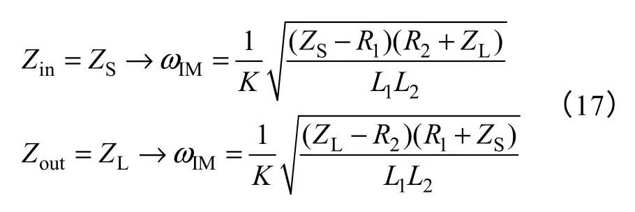
Obviously,the optimal angular frequency should achieve a consistent only when ZS/ZLis equal to R2/R1.Substituting (17) to (12),(13) and (14),PL,ηE,ηT,Zinand Zoutare derived as below when impedance of 2-port network is matched,respec-tively

As shown in in Fig.2,if ZLis not equals to ZS,the output port of 2-port network can add L,T or π type impedance matching network to realize the impedance matched,it can effectively improve the load power and transmission efficiency.
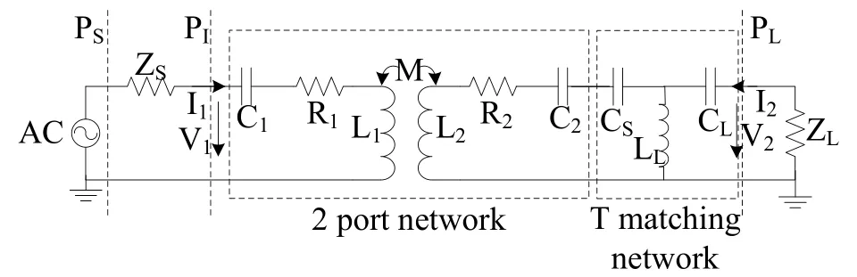
Fig.2 Block diagram of the WPT system after add impedance matching network
2.2 Maximum power mode
We can obtain the specific angular frequency to reach the maximum load power as the coupling coefficient changes by setting the derivative of (12) to zero to solve for ω.
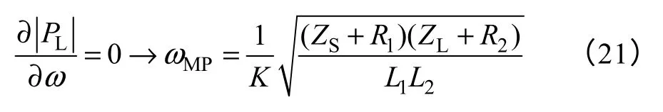
Substituting For.(21) to (12),(13) and (14),the PL,ηE,ηT,Zinand Zoutwhen PLis maximum are derived as below,respectively.

Compare to the maximum power mode and impedance matching mode,the maximum power mode has better performance than impedance matching mode,but the gap between two modes is very small.In maximum power mode,impedance matching can be realized through adjust the resonant frequency and the compensation capacitance.The impedance matching mode has many limitations on the load impedance ZL,so the impedance matching network is generally introduced to ensure maximize the power transfer and minimize reflections.
3 Model validation and experimental results
In order to design a WPT system that is applicable to tablet PC,ultrabooks,mobile phones and other low power devices,we designed a WPT system based on printed circuit boards (PCB) as shown in Fig.3.Recently,more and more WPT systems use PCB as the transmitter and receiver.PCB coils are suitable for applications where stringent space and height requirements have to be met.The PCB based WPT systems have many advantages,such as high precision,high consistency and easy to design and manufacture[13-16].The PCB copper thickness and width is limited,so the PCB cannot pass a large amount of current.In addition,the high frequency current through the PCB traces results in a large eddy current skin effect which leads to the PCB coil resistance to increase and the power loss to increase together at high frequency.Hence,the PCB coil based WPT is only suitable for low power devices.The prototype in this paper has a power rating of about 5W when the transmission distance is 30mm (k=0.3).In order to decrease the power loss at high frequency,we must increase the distance between the turns.This will decrease the PCB coil’s inductance and mutual inductance between the two PCB coils.So the PCB coil design must maintain a balance between efficiency,size,and power level.
The quality factor is an important parameter indicating the ratio of the power losses in the coils.The quality factor is defined as the ratio of coil inductance and resistance at a certain operating frequency.

The PCB coil design must ensure that the coil has a low resistance while has a high inductance.We use FEM software MAXWELL to accurately simulate the PCB coil and extract the electric parameters and optimize the coils’ structure design.The analysis and simulation below are based on the PCB coil,the PCB coil structure parameters and electrical parameters measured and simulated using finite element analysis software are shown in Tab.1.

Fig.3 The PCB spiral coil

Tab.1 Parameters of PCB Coil
3.1 Simulation analysis
The definition of the coupling coefficient and the mutual inductance is given by
The coupling coefficient between the primary and secondary coils is very important.The relation between coupling coefficient and distance &misalignment can be calculated using analytical methods or finite element analysis (FEA)[17-18].Fig.4 shows the coupling coefficient as a function of distance &misalignment obtained using FEA for the experiment setup.
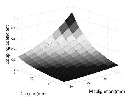
Fig.4 Coupling coefficient versus distance &misalignment

According to the parameters in Tab.1 and Tab.2,and substituting parameters to[21].Fig.5 shows transmission efficiency ηT,energy efficiency ηEand load power PLversus frequency with different load in maximum power mode when k=0.3,C1=1/(L1ω2) and C2=1/(L2ω2).

Tab.2 Parameters of simulation

Fig.5 Transmission efficiency,maximum load power versus frequency in maximum power mode
As shown in the Fig.5,when load power reach maximum,the transmission efficiency generally reach an ideal value but the energy efficiency close to 50%.In general,we concern with more power transfer and little consider the efficiency in high frequency WPT system.Impedance matching is necessary to maximum power transfer theorem,and it can ensure maximize the power transfer and minimize reflections,so the WPT system should be terminated in impedance matched at resonant frequency to provide the maximum transmitting power.Smith charts are extremely helpful for impedance matching,the centre of the smith chart is the point where the reflection coefficient is zero,which is where the input and output impedance is matched and the normalized load impedance Z=1+j0.
The simulated smith charts of S11are shown in Fig.6 based on the parameters in Tab.1 and Tab.2.In impedance matching mode,S11with different load all move from ∞Ω constant resistance to close the center of the smith chart at the same frequency after add impedance matching mode.If the 2-port network doesn’t add the impedance matching network in impedance matching mode,S11with load of 20 Ω and 50 Ω can’t move to the center of the smith chart and intersect with pure resistance line on resonant frequency.In maximum power mode,S11with different load move from ∞Ω constant resistance to close the center of the smith chart with different resonant frequency,when the input and output impedance of 2-port network is matched in different resonant frequency,the load power also reaches the maximum.

Fig.6 Smith chart of S11,frequency form 40 kHz to 8 MHz
3.2 Experiment analysis
As shown in Fig.7,a signal generator (4040 A) by BK Precision is used as a signal source,and a 5 W power amplifier is connected to the signal generator and the output impendence of the power amplifier is 50 Ω.A Tektronic oscilloscope (MDO4054-3) is used to measure the primary and secondary voltage waveforms,and the current probe is connected to the oscilloscope to measure the input and output current.

Fig.7 Picture of transmission efficiency measurement
Fig.8 shows the measurement and simulation results of the load power versus frequency with different load at the output power is equal to 5 W when k=0.3.The load power achieved the desired value in impedance matching mode and maximum power mode.Simultaneously,the transmission efficiency also exceeded 90% in both two modes.Because the performance of a WPT system can be affected by the deviation of the electronic components,skin effect,proximity effect,the parasitic capacitance,and the clamps &connectors,etc.The measured load power and efficiency cannot achieve the desired values from simulations,but the gap between the experiment and simulation less than 8%.
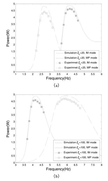
Fig.8 Power versus frequency at the output power is equal to 5 W when k=0.3
The WPT system can achieve power transfer with high efficiency of in both two modes,the operation frequency is consistent with different load in impedance matching mode,and the impedance matching realize through add the impedance matching network.In the maximum power mode,the impedance is matched when achieve a particular frequency,the particular frequency change as the load and coupling coefficient,etc.Impedance matching mode has a better performance than maximum power mode when the load impedance less than the source impedance,because the WPT system has a wider bandwidth and less affected by the skin effect of coils in impedance matching mode.But when the load impedance more than the source impedance,the WPT system of maximum power mode has a better performance and a wider bandwidth.
4 Conclusion
This paper studied and analyzed the performance of a wireless power transfer system using the 2-port network theory and ABCD-parameters for a PCB based WPT.First,we optimized the value of the operational frequency,compensation capacitance and impendence matching network in impedance matching mode and maximum power mode.Secondly,we verified by experiments that the load power and transmission efficiency are very high with different load when the impedance was matched in impedance matching mode and maximum power mode.
The prototype WPT system transfers about 5W power and the transmission efficiency exceeds 90%using the PCB coils in impedance matching mode and maximum power mode.The different application can select the appropriate optimized mode according to the actual application.Through the detailed theoretical analyzes and experiments of a PCB based WPT system,it reveals that 2-port network and ABCD parameters are an effective and practical method to study and analyze the WPT systems operating in the low radio frequency range.
Acknowledgment This work is supported by the National Natural Science Foundation of China(61104088),and the Scientific Research Fund of Hunan Provincial Education Department (12C0741).
Reference
[1]Kurs A,Karalis A,Moffatt R,et al.Wireless power transfer via strongly coupled magnetic resonances[J].Science,2007,317:83-86.
[2]Chwei-Sen W,Stielau O H,Covic G A.Design considerations for a contactless electric vehicle battery charger[J].IEEE Transactions on Industrial Electronics,2005,52:1308-1314.
[3]Seungyoung A,Joungho K.Magnetic field design for high efficient and low EMF wireless power transfer in on-line electric vehicle[C].In Antennas and Propagation(EUCAP),Proceedings of the 5th European Conference on,2011:3979-3982.
[4]Xun L,Ng W M,Lee C K,et al.Optimal operation of contactless transformers with resonance in secondary circuits[J].In Applied Power Electronics Conference and Exposition,2008,APEC 2008,Twenty-Third Annual IEEE,2008:645-650.
[5]Tan L,Huang X,Huang H,et al.Transfer efficiency optimal control of magnetic resonance coupled system of wireless power transfer based on frequency control[J].Science China Technological Sciences,2011,54:1428-1434.
[6]Chih-Jung C,Tah-Hsiung C,Chih-Lung L,et al.A study of loosely coupled coils for wireless power transfer,circuits and systems II:express briefs[J].IEEE Transactions on,2010,57:536-540.
[7]Seung-Hwan L,Lorenz R D.Development and validation of model for 95%-efficiency 220 W Wireless power transfer over a 30 cm air gap[J].IEEE Transactions on Industry Applications,2011,47;2495-2504.
[8]Teck Chuan B,Kato M,Imura T,et al.Automated impedance matching system for robust wireless power transfer via magnetic resonance coupling[J].IEEE Transactions on Industrial Electronics,2013,60:3689-3698.
[9]Wei W,Kawahara Y,Kobayashi N,et al.Characteristic analysis of double spiral resonator for wireless power transmission[J].IEEE Transactions on Antennas and Propagation,2014,62(1):411-419.
[10]Raju S,Wu R,Chan M,et al.Modeling of mutual coupling between planar inductors in wireless power applications[J].IEEE Transactions on Power Electronics,2014,29(1):481-490.
[11]Linhui C,Shuo L,Yong Chun Z,et al.An optimizable circuit structure for high-efficiency wireless power transfer[J].IEEE Transactions on Industrial Electronics,2013,60:339-349.
[12]Imura T,Hori Y.Maximizing air gap and efficiency of magnetic resonant coupling for wireless power transfer using equivalent circuit and neumann formula[J].IEEE Transactions on Industrial Electronics,2011,58:4746-4752.
[13]Tang S C,Hui S Y R,Chung H S H.Characterization of coreless printed circuit board (PCB) transformers[J].IEEE Transactions on Power Electronics,2000,15:1275-1282.
[14]Beams D M,Annam S G.Calculation of mutual inductance from magnetic vector potential for wireless power transfer applications[J],In System Theory (SSST),2012 44th Southeastern Symposium on,2012:209-213.
[15]Fotopoulou K,Flynn B W.Wireless power transfer in loosely coupled links:coil misalignment model[J].IEEE Transactions on magnetics,2011,47:416-430.
[16]Kainan C,Zhengming Z.Analysis of the doublelayer printed spiral coil for wireless power transfer[J],Emerging and Selected Topics in Power Electronics,IEEE Journal of,2013,1:114-121.
[17]Imura T,Okabe H,Uchida T,et al.Study on open and short end helical antennas with capacitor in series of wireless power transfer using magnetic resonant couplings[C].In Industrial Electronics,2009.IECON '09.35th Annual Conference of IEEE,2009:3848-3853.
[18]Raju S,Rongxiang W,Mansun C,et al.Modeling of mutual coupling between planar inductors in wireless power applications[J].IEEE Transactions on Power Electronics,2014,29:481-490.