Optimization and Characteristic Analysis of Wireless Power Driven Vehicle Featuring Magnetic Coupled Resonance
2015-11-25 09:32ZhangPengchengYangQingxinZhangXianYuanZhaoyangSuHang
电工技术学报 2015年1期
Zhang Pengcheng Yang Qingxin Zhang Xian Yuan Zhaoyang Su Hang
(Tianjin Key Laboratory of Advanced Electrical Engineering and Energy Technology,Tianjin Polytechnic University Tianjin 300387 China)
1 Introduction
Wireless power driven vehicle can work without conductor exposure,sliding contact of pantographs by trolley bus applied nowadays.It is proposed with the characteristics of green,safe and non-contact.Traditional wireless power driven vehicle utilizes inductive power transfer[1-2]which delivers power at high efficiency within a very close distance comes with the disadvantage of fluctuating in efficiency due to distance changes caused magnetic leakage variation in the air gap.Inductive power transfer fits applications in very close distance and fixed routes.Taking the air gap of primary side and secondary side of transformers as an example,they usually operate at very high efficiency within a short distance with iron core to help enhance the magnetic flux between both sides,however in most cases the air gap between chassis and ground is larger than that in transformers,thus it would be better classified to mid-range applications.
In these occasions,inductive power transfer has its own limitations compared to magnetic resonant transfer.Power transmission through magnetic resonant is proposed to be a better solution for mid-range applications.Detailed analysis and theoretical derivation in[3]showed the efficiency and possibility of mid-range power transfer.
Practical applications showed that even slightly fluctuation in load conditions would add to the instability of system performance,leading to power losses and even off-resonant.Thus making the system operating under stable condition would be a key factor in designing a system.
In order to enhance the stability of system performance,to extend transmission distance and efficiency is an effective way.A structure featured a coil named strengthened relay coil that helps to extend transmission distance was proposed and detailed explained in[4].Different models aiming at accurately estimate the system transmission capacity and efficiency are proposed[5-8].However,how the relay coil is to balance the parameters between transmission coil and receiver coil and to adjust the position of strengthened relay coil and receiver coil according to different conditions is a key problem that is not being detailed considered.
In this paper,we are going to investigate and analyze the performance of wireless power driven vehicle system featuring magnetic coupled resonance under the assistance of relay coil.The relationship between system and several parameters of relay coil is studied.How the relay coil effect the system performance was analyzed.A FEM model is introduced to analyze the performance of transmission system with relay coil.Experiment was also carried out to verify theoretical derivation.
1 Fundamental Analysis
The proposed architecture of transmission system with relay coil is shown in Fig.1.Transmission coil is a several-turns loop made of Litz wire under the ground to ease the influence of skin effect.The distance between two paralleled lines should be around 70 cm,which is close to the wheelbase dimension of existing vehicles.A receiver coil is attached on the surface of chassis and a relay coil is placed axial aligned.FR4 board is applied here to separate the receiver coil form relay coil.The distance between relay coil and receiver coil can be adjusted to obtain the best efficiency.In this design,transmission coil is much larger than receiver coil and strengthened relay coil in dimension.

Fig.1 Architecture of coupling system for online powered vehicle with relay coil
With the presence of strengthened relay coil,the resonance coupling can interact more strongly between the transmitter coil and receiver coil.The following equations shows the corresponding power in each coil when these coils are in resonance where subscript 1,2 and 3 represent transmitter coil,relay coil,and receiver coil respectively,a1(t),a2(t) and a3(t) denote the forward transfer mode of transmitter coil,relay coil,and receiver coil respectively.ω10,20,30denote the natural resonant frequency of each coil.κ denotes the mode coupling factor.Γ1,Γ2and Γ3denote the intrinsic loss of each coil.ΓLis the intrinsic loss due to the load resistance.Asejωtis the initial value on transmitter coil as a sinusoidal signal source with the amplitude Asand the angular frequency ω.

The voltage induced in receiver coil is in inversely proportion to the separation between relay coil and receiver coil in theory.As relay coil is a coil with no load and is tuned to the same frequency with the magnetic field,it would gather the magnetic flux around it and excites a high electric field.
To simplify the problem while analyzing the current in load,the load is supposed to be resistive which will not bring shifts in system coupling.Then the transmission system can be expressed by adopting mutual inductance model as shown in Fig.2.

Fig.2 Mutual inductance model of transmission system
In this system,I0is the current of a constant current source,then Rsis the resistance of the source coil.Lsand Csare the inductance and capacitance of the source coil respectively.Lsand Csare tuned into resonance.Rr,Lrand Crrefer to the resistance inductance and capacitance of relay coil respectively.Iris the current in relay coil.Rsand Rrare relatively small in value compared to Rl,which is the resistance of load.Similarly,Rl,Lland Clare resistance inductance and capacitance of the receiver coil and Ilis the current in receiver coil.These three coils interacts with each other through magnetic coupling and M12is the mutual inductance between source coil and relay coil.M23is the mutual inductance between relay coil and receiver coil then M13refers to the mutual inductance between source coil and receiver coil.In this application,relay coil is close to receiver coil compared to the distance between source coil and relay coil.In this way,mutual inductance between relay coil and receiver coil is much larger than that between source coil and the other two coils.The transmission system is supposed to be in resonant state in which the resonant frequency is ω.Then KVL relations between three coils can be expressed as formulas listed below.

To simplify its expression,Zrand Zlare used to illustrate the impedance of relay coil and receiver coil.

The current in relay coil and receiver coil can be obtained by derivation.The following equations shows the interactions between coils which reflected as current changes.

Impedance of each coil can be fixed when the frequency of source is determined.However in most cases,there is certain fluctuation in system resonant frequency due to interference in inductance and capacitance caused by coils misalignment and distance changes between coils.In these cases,impedance of each coil cannot be resistive,thus making it inaccurate to simplify impedance parameters of each coil in computation.When all the coils are in resonant state,it can be observed that current in load comes as a function of mutual coupling between coils and coil impedance.
Mutual inductance between coils can be calculated by Neumann’s Formula as below.μ0is the vacuum permeability and dl1,dl2means the unit differential element on the coils.r is the distance between coils and θ is the angle between dl1and dl2.

Finally,the voltage of load can be calculated as Eq.(6).

3 Simulation and experiment
In simulation,a transmission system with three coils was built where the parameters are listed in the table below.The operation frequency in this simulation was fixed at 90 kHz and these three coils are all tuned to this fixed frequency by capacitor compensation.
The three coils are all defined as homogeneous numerical coils and the transmitter coil is excited with a 90 kHz sinusoidal signal.Fig.3 shows the magnetic flux distribution around the relay coil and receiver coil slice with a axial distance of 15 cm.Relay coil lays on the lower part of the cloud image.The magnetic flux around the relay coil is stronger than that around the receiver coil.This is because the relay coil is simulated with a very low resistance and no load,thus making it a ideal high-Q oscillator where power exchanges between magnetic field and electric field with very low loss.Besides,the relay coil is close to receiver coil which will provide a higher coupling factor that builds a closer linkage between them.

Fig.3 Magnetic flux distribution around the relay coil and receiver coil
Then the distance between relay coil and receiver coil is adjusted.Fig.4 shows the magnetic density of the system when adjusting the distance between coils.It can be observed that the magnetic density gets better strengthened when the distance between relay coil and receiver coil is 15cm compared to the distance of 10cm and 20cm.It can be assumed that there is a certain optimal distance between these three coils when the parameters of coils are fixed.

Fig.4 Magnetic distribution around relay coil and receiver coil
In experiment,a prototype applying parameters shown in Tab.1 was made to verify computational results.A 200 Ω resistor is used as load here.The current and power through the resistance can be obtained by checking the voltage through the resistance while the distance changed from 2 cm to 27 cm.A constant current source is used here to excite these coils.The distance between transmission coil and receiver coil is set to be fixed at 45cm,which is a quite long enough distance for wireless charging.By adjusting the distance between relay coil and receiver coil,voltage variations induced on load can be measured.
The experiment design is illustrated as below.

Tab.1 Parameters of coils equipped with resonant capacitor in transmission system under 90 kHz
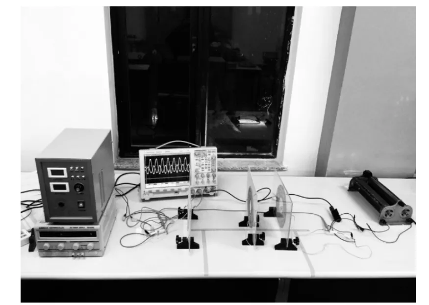
Fig.5 Prototype measuring the voltage on load
Induced voltage was measured respectively under the conditions that current ranged from 3.2 A,2.6 A to 1.9 A was excited in source coil.The distance between source coil and relay coil is fixed then adjusting the distance between relay coil and receiver coil.The horizontal refers to the distance between relay coil and receiver coil.Measured results and normalized voltage amplitude of simulation results are plotted in the chart below.The longitudinal axis on the left side is the load voltage measured on load under different exciting current and the longitudinal axis on the right side is the normalized voltage amplitude on load which refers to the smooth curve in the chart.
It can be seen from the chat that in all three situations,with the increasing of the distance,the measured curves under three current conditions feature a trend of increasing first then decreasing.The curves all increase when the distance between relay coil and receiver coil increase from a very close distance.
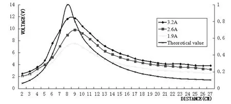
Fig.6 Measured results and normalized theoretical value of voltage induced on load under different excitations
At the distance of 8 cm,the voltage on load achieves its maximum under all three current conditions.With the distance continues to increase,the voltage on load decreases.
The normalized theoretical value which has the highest peak in chart also featured the same trend with measured data.The curve reaches maximum at 7 cm which is close to experiment results.From 2 cm to 7 cm,the curve goes up and after 7 cm,it goes down.
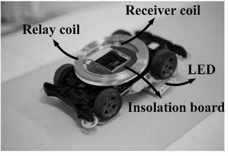
Fig.7 Architecture of the model
The voltage growth is contributed by the magnetic flux gathered by relay coil and the excited electric field and magnetic field around the relay coil.When the system works in the regime of critical coupling,the load voltage achieved maximum which is similar to the characteristic of traditional transmission system[9].By adjusting the distance between relay coil and receiver coil,the system can be tuned into critical coupling state.
A prototype applying the design was produced as shown in Fig.6.A four-wheel drive is remodeled for this design.A LED lamp was installed on the top of the drive to help better observing the trace of the drive.The rated power of the motor is 5W and the rated power of LED lamp is 5W.The total amount of power of the prototype is 10W.The transmission coil is placed under the track.The distance between the receiver coil and transmission coil is 2.8 cm and the optimal distance between the relay coil and receiver coil is 5mm for this coil dimension according to experiment.So the relay coil is placed 5mm under the receiver coil with an insolation board between them.The white lines in Fig.7 show the trace of the movement.

Fig.8 Prototype in operation
Compared to the prototype adopting a traditional two-coil structure without relay coil,the measured efficiency of the proposed structure has a significant increase from 65.3% to 86.7%.
4 Conclusion
In this paper,the output power of proposed wireless transmission system for electric vehicle is analyzed and experimented under different excitations.The current on load is derived by mutual inductance model.As the employment of relay coil would strengthen the efficiency of wireless power driven vehicle.The distance between relay coil and receiver coil should be calculated and the relay coil should be placed properly in the system.Improper placement of relay coil would not benefit the system output power to the largest extend and how to balance the system structure depends on system parameters like resonant frequency,coil structure and coil impedance.Wireless power transmission system applied to electric vehicle should be optimized according to different coil structure and transmission distance to achieve optimal.
Reference
[1]Yang Qingxin.Research progress in contactless power transmission technology[J].Transactions of China Electrotechnical Society,2010.25(7):6-13.
[2]Sungwoo L,et al.On-line electric vehicle using inductive power transfer system[J].In Energy Conversion Congress and Exposition (ECCE),2010 IEEE.2010.Atlanta,GA.
[3]Kurs Andre, et al.Wireless power transfer via strongly coupled magnetic resonances[J].Science,2007.317(5834):83-86.
[4]Zhang Fei,et al.Relay effect of wireless power transfer using strongly coupled magnetic resonances[J].IEEE Transactions on Magnetics,2011.47(5):1478-1481.
[5]Huang Xueliang,et al.Comparative study on the two kinds of models in the technology of magnetic coupling resonance system[J].Transactions of China Electrotechnical Society,2013.28(2):171-176,187.
[6]Zhai Yuan,et al.Modeling and analysis of magnetic resonance wireless power transmission systems[J].Proceedings of the CSEE,2012,32(12):155-160.
[7]Luo Bin,et al.Modeling and analysis of magnetic resonance coupling wireless relay power transfer system with single intermediate coil resonator[J].Proceedings of the CSEE,2013.33(21):170-177.
[8]Wang Wei,et al.Modeling and transmission efficiency analysis of wireless power transmission system with dual relays[J].Transactions of China Electrotechnical Society,2014.29(9):1-6.
[9]Zhang Xian,et al.Research on characteristics of frequency splitting in electromagnetic coupling resonant power transmission systems[J].Transactions of China Electrotechnical Society,2012.32(9):167-172.