
Fast Scheme for Projective Geometric Correction and Edge Blending Based on High Dynamic Range Images
2015-12-20 09:14LIUZhejun柳喆俊JINYunshui金云水
关键词:云水
LIU Zhejun(柳喆俊),JIN Yunshui(金云水)
College of Communication and Arts,Tongji University,Shanghai 200092,China
Introduction
Multi-channel projection is widely used in the industry of virtual reality and entertainment to enable large scale immersive visualization.Those immersive displays include cylindrical screen projection,dome screen projection,and projection on other “encompassing”surfaces of arbitrary shapes.
Multi-channel projection used to be very specialized and expensive.In the past,a special device called “edge blender”must exist to receive the original video signal,process it and then output multiple signals to different projectors.This device normally costs 200 000to 400 000 RMB(around 33 000to 66 000USD),which prominently raises the total cost to construct immersive visualization systems.
In 2010,advanced micro devices(AMD)introduced“ATI Radeon HD 58XX”series video adapters together with“eyefinity”technology,enabling a single video card to output six signals at the same time,making it possible to run a real-time interactive application with geometric correction and edge blending functions on a single computer,and thus greatly lowered the investment.
In 2012,we successfully actualized a multi-channel stereoscopic projection on a 120°cylindrical screen with six polarized liquid crystal display(LCD)projectors and a single computer equipped with“ATI Radeon HD 5870”via high level shading language (HLSL)coding.Practically,it worked perfectly as far as the final visual result was concerned.Moreover,regarding performance and usability,it had the following defects.
Firstly,the “performance hit”was not negligible.Because we used six projectors at extended graphics array(XGA)resolution(1 024pixels×768pixels),the rendered image became as large as 3 072pixels×1 536pixels.Even without geometric correction and edge blending,this highres real-time 3D application had already posed a big challenge for modern computers.Consequently, it's worthwhile to save as many computational resources as possible.
Secondly,the program could not be easily reused in another development environment or on another platform.Everything introduced in this paper was done in the“Quest3D”game engine using HLSL language,but not all game engines supported HLSL.For instance,“Unity3D”uses its own shading language called “ShaderLab ”, while“openFrameworks”,apopular tool for interactive application development,uses OpenGL shading language(GLSL).A great deal of uninteresting labor is needed to translate the codes for them.
According to our investigation,much relatively earlier research was about the improvement of the quality of geometric correction[1]and edge blending[2-3].Later researchers gradually turned their attention to the automation of the process,and thus figured out a number of smart schemes to reduce tedious human labor:Ref.[4]introduced an approach using structured light and an un-calibrated camera to obtain operational parameters,and Ref.[5]turned to a set of calibrated stereo cameras.In these schemes,scale-invariant feature transform (SIFT)and phase-only correlation (POC)were usually used as image correlation methods to aid geometric correction[5-6],while photo-based brightness evaluation was used to aid edge blending[4].Some articles do mention the use of graphic processing units(GPUs),but they either mention it in vague ways as in Refs.[4-7],or use a GPU as a faster substitute for a CPU,and run the same algorithms directly on them as in Refs.[8-10].These efforts are all meaningful and valuable to this investigation,but the fastest and most compatible approach is not yet discovered.
Therefore,a new scheme is needed to solve all the problems mentioned above and make immersive visualization easier and cheaper for everyone as well.
1 Experiment Environment
1.1 Hardware configuration
The hardware system was part of the“non-planar screen lab”in the College of Arts and Media of Tongji University.Because this system was built in accordance with the idea of“lower cost,better performance”,it didn't contain any fancy devices.Specifications of the relevant core hardware are shown in Table 1.
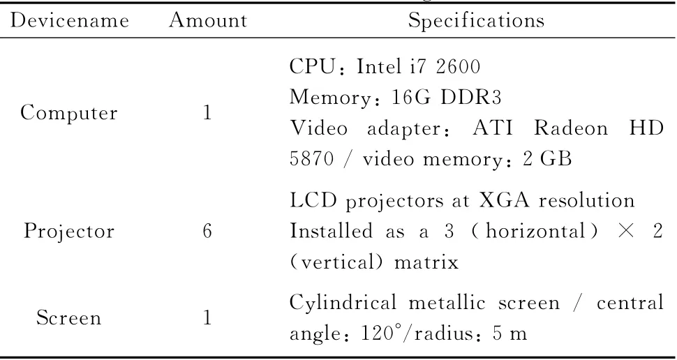
Table 1 Hardware configuration
1.2 Software configuration
Our program was developed with HLSL language in Quest3D4.3.2/5.0,and tested on 64bit Windows 7.
The scheme includes two programs,one for high dynamic range(HDR)image generation and the other for rendering.Since they are not interdependent,any other program or game engine may be used for rendering as long as it supports programmable shading pipeline.
If HDR images must be generated by another application,besides programmable shading pipeline,make sure this application also supports the HDR render to texture(RTT)function and is able to save RTT results as uncompressed HDR image files.
2 Introduction to the Scheme
The basic schemes are as follows.
Firstly,no matter how complicated the algorithms for geometric correction are, what they essentially do is translating (and interpolating)pixels in screen space.Similarly,edge blending algorithm essentially darkens specific pixels to certain degrees.They only depend on every device's position,orientation and optical properties.In simple terms,parameters for geometric correction and edge blending won't change unless a device,either a projector or the screen,is replaced or moved.Otherwise, once calculated,the calibrated result can be kept for future reuse.
Secondly,using a lookup table(LUT)is usually much faster than runtime computation.Since geometric correction and edge blending parameters don't change at runtime,they are good candidates for LUT method.
Thirdly,unlike low dynamic range (LDR)images whose pixels can only have discrete integers between 0and 255in R,G or B channel,HDR images can hold floating point numbers.Commonly,an HDR photo uses its RGB channels to keep color and brightness information,but actually they are in substance three arrays of floating point numbers and can be reserved for any other purposes if you want.
With the premises above,the scheme proposed in this paper includes three stages.
Stage 1,brute force calibration.A working program capable of geometric correction and edge blending for the target immersive display is created.
Stage 2,HDR image generation.Specially prepared HDR images are fed to the program created in stage 1,and the calibrated result is stored as an uncompressed HDR image to be used as an LUT in the future.
Stage 3,geometric correction and edge blending with an HDR images.Thanks to the HDR image generated in stage 2,now the input images can be processed very fast and easily.
These three stages are introduced in more details below.
2.1 Stage 1:brute force calibration
In our case,the interactive application is a virtual reality (VR) program.The brute force calibration procedures are shown in Fig.1.
Step 1:creating left,central,and right images
Three cameras are moved to the same point in space.They have different yaw angles and their view frustums touch each other precisely as shown in Fig.2.
Step 2:convert to cylindrical camera
When images are put side by side,although there is no visible seam between them,there are“folds”along seams,which suggests perspective discontinuity.Images from three pinhole cameras need to be distorted in a way illustrated in Fig.3to mimic the image from a cylindrical camera.
Step 3:generate overlapping areas

Fig.1 Procedures of brute force calibration
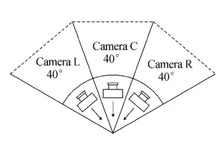
Fig.2 Arrangement of virtual cameras
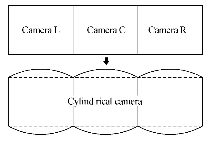
Fig.3 From pinhole camera to cylindrical camera
Edge blending happens along the adjacent edges of neighboring projections.Each projected image has a soft edge(or two soft edges when in the middle)that gradually fades to black.Adjacent projections must have some overlapping areas(i.e.,areas with identical content),so that nothing is lost in the process of edge blending.
By specifying variables “EdgeWidth1 ” and“EdgeWidth2”,we may calculate the overlapping areas as shown in Fig.4.

Fi.4Generatinoverlainareas
Step 4:nonlinear transform
Common projectors create rectangular images only on planar surfaces.On a cylindrical screen,the shape of a projected image usually looks like a barrel lying on its side.Again,it must be“squashed”to fit the screen.This is almost an inverse process of step 2so that further explanations are omitted.
Step 5:generate falloff areas along edges
To normalize brightness in the overlapping areas,the closer a pixel lies to a border the more it is darkened.But this falloff is not linear because the gamma values of projectors are normally other than 1.The relationship between a pixel's brightness multiplier I and its horizontal position U (relative to the edge)is:

The variableγ (aprojector's gamma value)commonly equals 2.2.To provide more flexibility,we use the refined equation proposed by Bourke in Ref.[3],and it becomes Eq.(2).
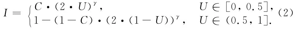
In Eq.(2),variable C controls the brightness of the vertical line of pixels in the horizontal center of a blended edge.
Step 6:linear transform
Optimally,aprojector shall be aligned perfectly so that its optical projection plane is parallel to the target planar surface,or perspective distortion will happen.But in real life,almost all projectors cause perspective distortion which can be corrected using their“keystone”functions.But it's more convenient and flexible to integrate the perspective correction function via a linear transform operation in the program.Equations (3)proposed by Kimat al.[11]and others[12]are used in this case.By specifying the locations of four corner points,perspective distortion correction can be performed easily,as shown in Fig.5.

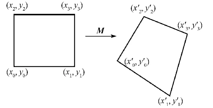
Fig.5 Linear transform for perspective distortion correction
Step 7:final step
Finally,in this step,we obtain the output image processed by both geometric correction and edge blending functions.
Last but not least,in all the seven steps mentioned above,the input and output images must remain in HDR format.
2.2 Stage 2:HDR image generation
Just like other post processing functions,geometric correction and edge blending happen on a plane primitive exactly as large as the screen.Commonly,its unitized UV coordinate values start at the upper left corner with(0,0)and end at the lower right corner with(1,1).Therefore,the position of a pixel on the screen can be described in either pixel space or UV space.The relationship is shown in Eq.(4),where wis the number of pixels in width,hin height.
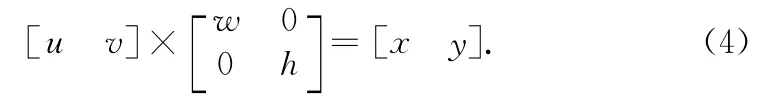
Suppose a pixel originally at(x1,y1)must be moved to(x2,y2)due to geometric correction.From the perspective of post processing,what actually happens is that color information from pixel(u1,v1)in the original image is taken to render pixel(u2,v2)in the target image,as shown in Fig.6.In this case,if 2Dvector(u1,v1)is already stored in pixel(u2,v2),the rendering program knows immediately from which pixel in the original image it shall take color information.Since UV values can be easily converted to and fromXYvalues using Eq.(4),for the sake of better precision,coordinate values are chosen to be stored in pixel space instead of UV space.
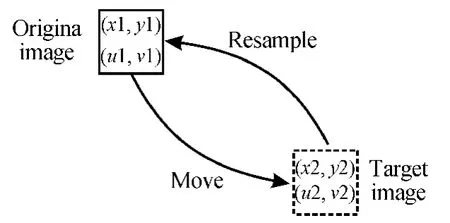
Fig.6 Pixel translation in the process of geometric correction
A special HDR image must be created as the reference image,and then fed to the“brute force”geometric correction program.In our case,an HDR image was created in such a way that its Rvalues go from 0to 3 072(=1 024×3)and Gvalues go from 0to 1 536(=768×2)as shown in Fig.7.In other words,each pixel in the reference image records its own coordinate values in the Rand Gchannels.As for the blue channel,each pixel has a“1”in it,which means 100%brightness.After edge blending operations,these values will be reduced correctly,becoming multipliers to dim the overlapping areas of the target images.
Fig.7 Reference image for geometric correction
Because the edge blending operations are not supposed to affect Rand Gchannels,the reference image must be processed by the brute force algorithms twice:the first time without edge blending and the second time with it.Then,the R,G channels from the first image and the B channel from the second image shall be combined together to create the final HDR image needed.It is also possible to modify the brute force program so that it affects Bchannel only during edge blending operations.
Finally,an output file type must be chosen to save this“distorted”reference image.Obviously it must support HDR values,or any value other than integers between 0and 255will be truncated.So common file types such as“.bmp”,“.tif”,and“.tga”are not acceptable options.
Moreover,it shall not perform any kind of lossy compression during saving,or severe artifacts will be easily introduced.As a result,“.hdr”type is not an option either.
In our case“.dds”file type in A32B32G32R32Fformat was chosen because it met the above criteria.When opened in photoshop or other similar software,this HDR image might look like a big block of bright solid colors.This is because most of the pixels have values beyond the valid range of an LDR monitor,but they shall work correctly when used in stage 3.
2.3 Stage 3:HDR image based processing
This step is simple and straight forward.Now that an HDR image is ready with its R,G,and Bchannels filled with modified UV coordinates and pixel brightness multipliers,and with HLSL or another shading language geometric correction and edge blending can be easily performed.Key codes in the pixel shader are shown in Fig.8,where“HDRSampler”is for the HDR image and the“InputImageSampler”is for the rendering result from the virtual reality program.
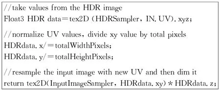
Fig.8 Key codes in the pixel shader
3 Evaluation and Comparison
Several scenes were used to test the scheme proposed in this paper.The results were visually perfect,as shown in Fig.9,although they were not identical to those processed in the brute way.

Fig.9 Results of geometric correction and edge blending
Unless the results were inspected closely and carefully enough,it was almost impossible to notice any difference.But if the same screenshots from two methods were taken and subtracted from each other,it was possible to see sparse bright pixels against black background,suggesting minor differences.Figure 10shows the results of subtraction.
To compare performance,“Intel Graphics Performance Analyzers(GPA)2013”was chosen to analyze two different scenes.Scene A is a simple scene with a few buildings and trees,and scene B is a complex scene with a lot of objects.The test results are shown in Fig.11.

Fig.10 Difference between two methods(cropped region)
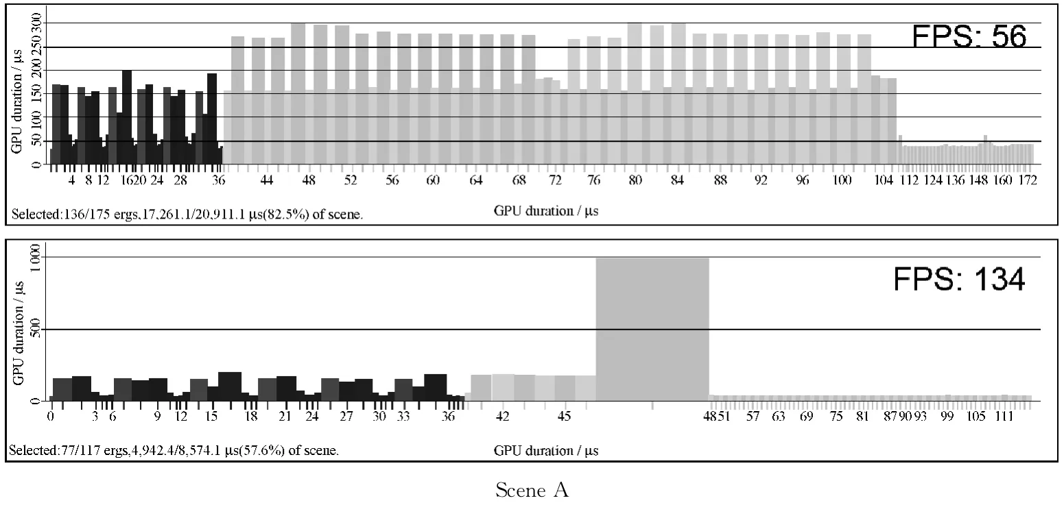
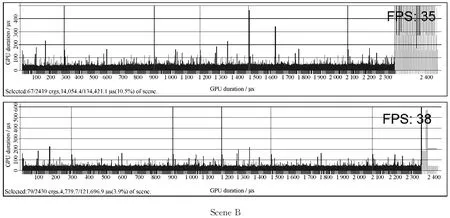
Fig.11 Analysis results from Intel GPA 2013
For scene A,because of its simplicity“brute force”method used 82.5%of the total GPU time,the HDR method only used 57.6%.The framerate went amazingly from 56to 134.For scene B,the bottle neck was no longer geometric correction and edge blending because of its complexity.The“brute force”method took 10.5% of the total GPU time while the HDR method reduced it to 3.9%,resulting in a 3fps speed increase.It was not as dramatic as scene A,but still meaningful.
4 Conclusions
In conclusion,as an optimized way to perform geometric correction and edge blending,the scheme proposed in this paper has distinct advantages and drawbacks.The advantages are as follows.
(1)High performance:by dumping calibration results into a single HDR image,the amount of runtime computation is greatly reduced,resulting in an obvious speed boost especially for modest scenes.(2)Flexibility:because all the information needed for geometric correction and edge blending is organized into an HDR image in a straight forward way,various 3Dengines on different platforms can make use of it with very few lines of codes.
However,the drawbacks are as follows.(1)Inaccuracy:although accurate enough for practical usage,the final result created with this method is still different from the image processed directly in the“brute force”way,because of the interpolations happening during resampling steps and the intrinsic inaccuracy of HDR images.It normally doesn't exert a noticeable impact on most applications,but can still be a potential problem in highly demanding situations.(2)GPU dependency:scheme in this paper is very fast only when the processing power of GPUs comes into play.If the target application doesn't support programmable shader,this method is not applicable.This is an inevitable disadvantage when compared with a hardware edge blender.
[1]Bhasker E S,Majumder A.Geometric Modeling and Calibration of Planar Multi-projector Displays Using Rational Bezier Patches[C].Conference on Computer Vision and Pattern Recognition,USA,2007:1-8.
[2]Song Z J,Gong G H,Huang Z P,et al.A New Edge Blending Paradigm for Multi-projector Tiled Display Wall [C].2010 International Conference on Computer Application and System Modeling,China,2010:349-352.
[3]Bourke P.Edge Blending Using Commodity Projectors [OL].(2004)[2014-10-08].http://paulbourke.net/texture_colour/edgeblend/.
[4]Harville M,Culbertson B,Sobel I,et al.Practical Methods for Geometric and Photometric Correction of Tiled Projector Displays on Curved Surfaces[C].2006 Conference on Computer Vision and Pattern Recognition Workshops,USA,2006:5.
[5]Ito K,Takahashi T,Aoki T.A Geometric Correction Method Using Stereo Vision for Projected Images[C].2011First Asian Conference on Pattern Recognition,China,2011:515-519.
[6]Takahashi T,Kawano T,Ito K,et al.Performance Evaluation of a Geometric Correction Method for Multi-projector Display Using SIFT and Phase-only Correlation[C].2010Proceedings of 17th IEEE International Conference on Image Processing,China,2010:1189-1192.
[7]Zeng H,Zhang J D,Ma L S,et al.Fast Multi-projection Image Geometric Calibration and Edge Blending Method[J].Computer Engineering and Design,2013,34(5):1846-1850.(in Chinese)
[8]Zhou Y X,Qin K H,Luo J L.GPU-Based Geometric and Photometric Corrections for Multi-projector Autostereoscopic Display [J].Journal of Computer-Aided Design & Computer Graphics,2011,23(4):561-570.(in Chinese)
[9]Luo S H,Zhang J.GPU-Based Barrel Distortion Correction for Acceleration[C].2013IEEE International Conference on High-Performance Computing and Communications & 2013 IEEE International Conference on Embedded and Ubiquitous Computing,China,2013:845-848.
[10]van der Jeught S,Buytaert J A N,Dirckx J J J.Real-Time Geometric Lens Distortion Correction Using a Graphics Processing Unit[J].Optical Engineering,2012,51(2):027002-1-5.
[11]Kim D K,Jang B T,Hwang C J.A Planar Perspective Image Matching Using Point Correspondences and Rectangle-to-Quadrilateral Mapping[C].The Fifth IEEE Southwest Symposium on Image Analysis and Interpretation,USA,2002:87-91.
[12]Heckbert P.Projective Mappings for Image Warping —Fundamentals of Texture Mapping and Image Warping[D].USA:U.C.Berkeley,1989:17-21.
猜你喜欢
金山(2022年8期)2022-09-06
成都信息工程大学学报(2021年2期)2021-07-22
宝藏(2021年1期)2021-03-10
艺术品鉴证.中国艺术金融(2018年10期)2019-01-08
幸福家庭(2019年14期)2019-01-06
民间故事选刊·上(2018年3期)2018-03-17
故事会(2017年19期)2017-10-11
人事天地(2017年5期)2017-05-18
宝藏(2017年4期)2017-05-17
宝藏(2017年3期)2017-05-09
 Journal of Donghua University(English Edition)2015年2期
- Journal of Donghua University(English Edition)的其它文章
- Analysis of Co3O4/ Mildly Oxidized Graphite Oxide (mGO )Nanocomposites of Mild Oxidation Degree for the Removal of Acid Orange 7
- Ontology-Based Semantic Multi-agent Framework for Micro-grids with Cyber Physical Concept
- A Motivation Framework to Promote Knowledge Translation in Healthcare
- Aircraft TrajectoryPrediction Based on Modified Interacting Multiple Model Algorithm
- Two Types of Adaptive Generalized Synchronization of Chaotic Systems
- A Dependent-Chance ProgrammingModel for Proactive Scheduling