
A two-stage blade-packing rotating packed bed for intensification of continuous distillation☆
2016-05-29 10:58YongLuoGuangwenChuLeSangHaikuiZouYangXiangJianfengChen
Yong Luo ,Guangwen Chu ,*,Le Sang ,Haikui Zou ,Yang Xiang ,Jianfeng Chen ,2,*
1 Research Center of the Ministry of Education for High Gravity Engineering and Technology,Beijing University of Chemical Technology,Beijing 100029,China
2 State Key Laboratory of Organic-Inorganic Composites,Beijing University of Chemical Technology,Beijing 100029,China
1.Introduction
Process intensification(PI)technology includes PI equipment and PI methods[1].As one of the typical PI equipment,rotating packed beds(RPBs)have been studied and utilized in chemical industries for last 35 years(starting at 1979)[2-6].An early structure of the RPB's rotor described in the US patent granted in 1981 was show n in Fig.1(a).The liquid was the continuous phase and the gas was the discontinuous phase in the rotor.Since the rotor was always filled with liquid,the RPB's motor load was very high and a significant amount of energy was consumed[7].The rotors' structures,show n in Fig.1(b)[8]and(c)[9],were optimized in the US patents granted in 1983,w here the liquid and gas were the discontinuous and continuous phases,respectively.More gas-liquid contacting area can be generated when the liquid is disintegrated by the high speed porous packing packed in the rotor,which benefits the mass transfer process.Asa common unit operation of mass transfer in the chemical industry,distillation is carried out by the gas and liquid contacting in a contactor.Because the gas fills the w hole RPB space and liquid flow s through in the rotor of the RPB as tiny liquid elements,which yields considerable interfacial area,mass transfer between two phases can be enhanced[10-12]in the RPB.As expected,continuous distillation in the RPB became the earliest application,which demonstrated the excellent performance of the RPB[13].
With the purpose of making the RPBa common contactor for continuous distillation,fundamental and application studies were conducted in RPBs by many researchers.The separation efficiency was measured in a one-stage RPBby total distillation experiments[14-17].Continuous distillation experiments were also conducted in atw o-RPB incorporated unit(one RPBas the rectifying section and the other as the strip ping section)[13,18,19].In order to install the intermediate feed along the radial direction of the rotating rotor,a rotating zigzag bed(RZB)was developed[20],which had multi-stage rotors driven by one motor,aiming at putting the continuous distillation in only one RPB unit.Recently,a new counter- flow concentric-ring rotating bed was reported for the continuous distillation which was upgraded from the RZB[21].A two-stage counter-current rotating packed bed(TSCC-RPB)for the continuous distillation was invented,constructed,and tested by the authors' group[22,23].Experimental results showed that the TSCC-RPB could provide remarkable separation efficiency.However,the structure of the TSCC-RPB,which had a static disc and a rotational packing in the rotor,was complicated.It required high manufacturing precision and the cost of the TSCCRPB was 10%-15%higher than that of a conventional RPB.

Fig.1.Rotor structure in the USRPB patent granted in(a)1981(b)and(c)1983.(a)1—stainless steel base;2—wall;3—transparent plastic lid;4—hollow shaft;5—radial channel;6—port;7—lip;8—annular groove;9—glass bead;11—radially inwardly disposed wire mesh;12—radially outwardly disposed wire mesh;13—outer concentric tube;14—inner concentric tube;15—gas—tight seal;16—fan sprays;17—bearing housing;18—stationary housing of stainless steel;19—port.(b)1—rotor;2—drive shaft;3—chamber;4—cover;5—base;6—chamber w all;7—packing;8—aperture;9—liquid feed pipe;10—gas feed pipe;11—by-passing of the packing;12—liquid seal;13—spiral;14—liquid discharge pipe;15—seal.(c)1—rotor;2—shaft;3—case;4—packing;5—liquid feed pipe;6—liquid discharge pipe;7—gas feed pipe;8—gas discharge pipe;9—seal.
End effect is a unique phenomenon in a RPB,with mass transfer accomplished in the end zone(radial thickness of 10-15 mm at the inner zone of the rotor)being amagnitudehigher than what is achieved in the bulk zone(the rest of the rotor).Based on the visual observation,the liquid was disintegrated into tiny liquid droplets in the end zone,but synchronized with packing in the bulk zone[24].In order to impinge the liquid in the bulk zone and generate more liquid interfacial area,a new designed RPB with blade packing(here called one-stage blade-packing rotating packed bed,OSBP-RPB)was reported,which enhanced the mass transfer in the w hole rotor[25].Experimental results show ed that the 60°blade-packing had the highest mass transfer efficiency.Combining the advantages of the TSCC-RPB and OSBP-RPB to develop a two-stage blade-packing rotating packed bed(TSBP-RPB)seems therefore a potential improvement.The aims of this development are:(1)to simplify the structure and(2)to maintain the same separation efficiency of the TSCC-RPB by replacing the static disc and rotational packing in the TSCC-RPB with the high efficiency 60°blade-packing in the OSBP-RPB.In this work,mass transfer parameters,presented in terms of the effective interfacial area(ae)and liquid side mass transfer coefficient(kL),of the TSBP-RPB were measured by the system of CO2chemisorption into NaOH solution.Then the TSBP-RPB was utilized in the continuous distillation of a methanol-water binary system to test the separation efficiency,presented in terms of the number of theoretical plates(NT).
2.Experimental Section
The TSBP-RPB,having tw o rotors with blade-packing in one rotational shaft,was constructed as show n in Fig.2(a).Dimensions of the TSBP-RPB are show n in Table 1.Fig.2(b)show s the structure of the blade-packing.Each blade-packing has three packing rings and two blade rings.The detailed structure of the blades can be found elsewhere in a previous paper[25].The inner and outer blade rings had 30 and 48 pieces of blades,respectively.The liquid distributor in the upper or lower rotor consists of four pipes con figured in parallel with the axis and each pipe has four nozzles aligned along the axial direction.The stainless steel w ire mesh was used as the packing and has a specific surface area of 500 m2·m—3and a porosity of 96%.
Fig.3 show s a sketch of the experimental setup for measuring mass transfer parameters of the TSBP-RPB.The NaOH solution(about 1 mol·L-1or 0.05 mol·L-1)at room temperature(20-25 °C)was pumped into the inner edge of the rotor from the stock tank.The mixed gas of CO2and air was tangentially introduced from a gas inlet and contacted the liquid counter-currently within the packing.The volume fraction of CO2in the mix gas was set on about 10%or 2%.Gas samples at the gas inlet and outlet were measured by tw o infrared gas analyzers(GXH-3010F,Huayun Analytical Instrument Company,China),respectively.Four liquid sample collectors were used and liquid samples were analyzed by an Automatic Potentiometric Titrator(Beijing Xianqu Weifeng Technology Development Co.,ZDJ-2D).The calculations of aeand kLwere reported elsewhere in a previous paper[22].

Fig.2.Main structure of(a)TSBP-RPB and(b)60°blade-packing.1—liquid outlet;2—liquid inlet 2(intermediate feed);3—blade packing;4—liquid inlet 1(re flux feed);5—gas/vapor outlet;6—liquid distributors;7—gas/vapor inlet.
Fig.4 presents the experimental setup of the TSBP-RPB for continuous distillation experiment.The solvent mixture containing methanol and water at room temperature(20-25°C)was pumped into the TSBP-RPB from the liquid inlet 2(intermediate feed,as show n in Fig.2)and contacted counter-currently with the vapor from there boiler in two stages.Vapor exited through the gas outlet and condensed in thecondenser.Part of the condensed liquid was collected as the product and the remainder was used as the re flux liquid which was pumped from the liquid inlet 1(re flux feed,as show n in Fig.2)into the TSBPRPB.A condenser pipe was used to condense the gas stream before top samples were taken from point A.In order to eliminate the influence of the reboiler,bottom samples were taken from point B before liquid enters the reboiler.The concentration of methanol in the samples was analyzed by a gas chromatograph(GC4000A,East&West Analytical Instruments Inc.,Beijing).The detailed calculation of NTcan be found elsewhere in a previous paper[21].
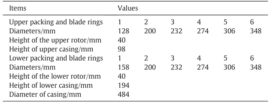
Table 1 Parameters of TSBP-RPB and stainless steel w ire mesh packing
3.Results and Discussion
3.1.Mass transfer
Figs.5-7 present the mass transfer results of the TSBP-RPB.The functional trends of aeand kLwith the operating parameters,such as rotational speed(N),liquid flow rate(L),and gas flow rate(G),are the main items of concern.
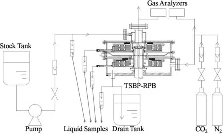
Fig.3.Flow chart of mass transfer experimental setup of the TSBP-RPB.

Fig.4.Flow chart of continuous distillation experimental setup of the TSBP-RPB.
Fig.6 displays the effect of liquid flow rate on the measured aeand kL.Firstly,Fig.6(a)show s that aeincreases with the higher liquid flow rate,ranging from 20 to 140 L·h-1.The wetted packing fraction could increase with the increase of the liquid flow rate,which would be favorable to enlarge the gas-liquid contacting area.Secondly,Fig.6(b)illustrates that kLdecreases slightly at first and then increases with the liquid flow rate.Apossible explanation for this phenomenon is given as follow s.
On the one hand,an increase in the liquid flow rate ranging from 20 to 120 L·h-1would be beneficial to the liquid velocity increase,but decrease the gas-liquid contact time;on the other hand,when the liquid flow rate is further increased,the shortened gas-liquid contact time at a higher liquid rate ranging from 120 to 140 L·h-1is compensated by the higher renewal frequency,thus a reverse effect on kLis observed.How ever,further exploratory studies are needed to assess the kLdependency.

Fig.5.Effect of rotational speed on(a)a e and(b)k L in the TSBP-RPB.
Fig.7 illustrates the dependence of aeand kLon the gas flow rate ranging from 1600 to 8000 L·h-1.As presented in Fig.7(a),aeincreases slightly in the beginning and then becomes sharply with the increase of the gas flow rate.Ahigher gas flow rate implies a higher gas flux flowing through the rotor,which is attributed to turbulence of gas and liquid in the blade-packing in the TSBP-RPB.Fig.7(b)presents the independence of gas flow rate on the parameter kL.The possible reason for this phenomenon is that the mass transfer process of CO2absorption is controlled by the liquid film and major mass transfer resistance exists in the liquid film[27,28].
3.2.Continuous distillation application
Fig.8 presents the separation efficiency of the TSBP-RPB for the application of continuous distillation.Effects of four operational parameters:rotational speed,re flux ratio(R),D/F ratio(D/F),and stock flow rate(F),on NTwere examined.
Fig.8(a)depicts that NTinitially obviously increases with the increase of rotational speed.How ever,NTstarts to decrease although slow ly w hen the rotational speed exceeds 700 r·min-1.It can be explained by the larger effective interfacial area resulted from the increase of rotational speed,benefiting to NT,as well as a shorter contact time,adversing to NT.The trend is similar to that found from the TSCCRPB[23].The optimal rotational speed of the TSBP-RPB was about 700 r·min-1.Fig.8(b)show s that NTincreases with the increase of R,which is common to the distillation practice.With the increase of R,more liquid from the product tank flow s back to the TSBP-RPB and it also increases the motor load.The optimal R was generally determined by considering the product output,energy consumption,and related pow er of the motor in practice.Fig.8(c)illustrates that the D/F ratio exerts a positive effect on NTwhich increases with the increase of the D/F ratio,varying in a range from 0.3 to 0.7.This suggests that NTis achieved with a greater numerical number at a higher D/F ratio.Fig.8(d)displays the effect of the stock flow rate on NT.It can be observed that NTincreased with an increase of the stock flow rate ranging from 6 to 18 L·h-1.More liquid could be split by the rotational packing which gained more liquid vapor area and consequently improved the mass transfer efficiency.The stock flow rate reveals a great effect on NT,which exhibits the same feature as the conventional packed columns.
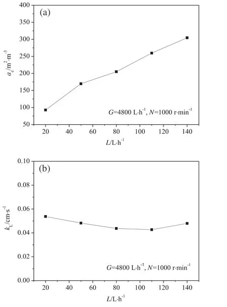
Fig.6.Effect of liquid flow rate on(a)a e and(b)k L in the TSBP-RPB.
The value of NTis determined not only by the operating conditions,but also by the dimension of the equipment.With a comparison to other Higee equipment,the separation efficiency is presented by the height of an equivalent theoretical plate(HETP).Table 2 show s that the TSBP-RPB maintains the equivalent separation efficiency as the TSCC-RPB.In comparison with RZB,the TSBP-RPB offers a higher separation efficiency.Moreover,the optimal rotational speed of the TSBP-RPB is lower than that for other Higee distillation equipment,which leads to a 17%-40%lower energy consumption.
4.Conclusions
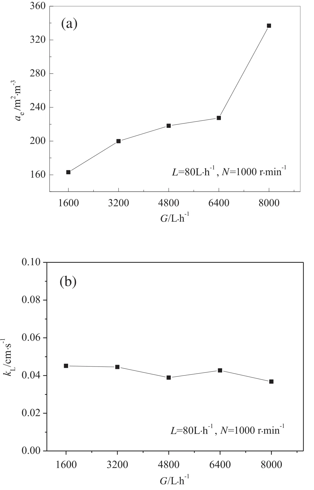
Fig.7.Effect of gas flow rate on(a)a e and(b)k L in the TSBP-RPB.
The TSBP-RPB,a two-stage blade-packing system,shows advantages over the TSCC-RPB.Experimental results show ed that the values of effective interfacial area and liquid side mass transfer coefficient of the TSBP-RPB were 93-337 m2·m-3and 0.05-0.19 cm·s-1,respectively.The HETP of the TSBP-RPB was about 1.9 to 10 cm under the operating conditions.In comparison with other Higee distillation equipment,the TSBP-RPB show s almost equivalent separation efficiency as the TSCCRPB,but is much easier to be constructed.Besides,the energy consumption of the TSBP-RPB was 17%-40%lower than that of the other Higee distillation equipment because of the lower optimal rotational speed.The study indicates that TSBP-RPB has potential application prospects in different separation processes w here the mass transfer rate is the limiting factor.
Nomenclature


Fig.8.Effects of(a)rotational speed,(b)re flux ratio,(c)D/F ratio and(d)stock flow rate on N T in the TSBP-RPB.

Table 2 Comparison of TSBP-RPB with other distillation equipment
[1]A.I.Stankiew icz,J.A.Moulijn,Process intensification:Transforming chemical engineering,Chem.Eng.Prog.11(2000)22-34.
[2]C.Ramshaw,R.H.Mallinson,Mass transfer apparatus and its use,European Patent,0002568,1979.
[3]D.P.Rao,A.Bhowal,P.S.Goswami,Process intensification in rotating packed beds(HIGEE):an appraisal,Ind.Eng.Chem.Res.43(2004)1150-1162.
[4]W.Wang,H.K.Zou,G.W.Chu,Z.Weng,J.F.Chen,Bromination of butyl rubber in rotating packed bed reactor,Chem.Eng.J.240(2014)503-508.
[5]H.Zhao,L.Shao,J.F.Chen,High-gravity process intensification technology and application,Chem.Eng.J.156(2010)588-593.
[6]H.Llerena-Chavez,F.Larachi,Analysis of flow in rotating packed beds via CFD simulations—dry pressure drop and gas flow maldistribution,Chem.Eng.Sci.64(2009)2113-2126.
[7]C.Ramshaw,R.H.Mallinson,Mass transfer process,US patent,4283255,1981.
[8]W.W.James,Centrifugal gas-liquid contact apparatus,US patent,4382045,1983.
[9]W.W.James,Centrifugal gas-liquid contact apparatus,US patent,4382900,1983.
[10]W.D.Sung,Y.S.Chen,Characteristics of a rotating packed bed equipped with blade packings and baffles,Sep.Purif.Technol.93(2012)52-58.
[11]L.L.Zhang,J.X.Wang,Z.P.Liu,Y.Lu,G.W.Chu,W.C.Wang,J.F.Chen,Efficient capture of carbon dioxide with novel mass-transfer intensification device using ionic liquids,AICHE J.59(2013)6957-6964.
[12]K.Guo,Z.Z.Zhang,H.J.Luo,J.X.Dang,Z.Qian,An innovative approach of the effective mass transfer area in the rotating packed bed,Ind.Eng.Chem.Res.53(2014)4052-4058.
[13]C.Ramshaw,HIGEE distillations—an example of process intensification,Chem.Eng.389(1983)13-14.
[14]T.Kelleher,J.R.Fair,Distillation studies on a high-gravity gas-liquid contactor,Ind.Eng.Chem.Res.35(1996)4646-4655.
[15]C.C.Lin,T.J.Ho,W.T.Liu,Distillation in a rotating packed bed,J.Chem.Eng.Jpn 35(2002)1298-1304.
[16]J.V.S.Nascimento,T.M.K.Ravagnani,J.A.F.R.Pereira,Experimental study of a rotating packed bed distillation column,Braz.J.Chem.Eng.26(2009)219-226.
[17]A.Mondal,A.Pramanik,A.Bhowal,S.Datta,Distillation studies in rotating packed bed with split packing,Chem.Eng.Res.Des.90(2012)453-457.
[18]H.Short,New mass-transfer find is a matter of gravity,Chem.Eng.90(1983)23-29.
[19]X.P.Li,Y.Z.Liu,Z.Q.Li,X.Wang,Continuous distillation experiment with rotating packed bed,Chin.J.Chem.Eng.16(2008)656-662.
[20]G.Q.Wang,Z.C.Xu,Y.L.Yu,J.B.Ji,Performance of a rotating zigzag bed—A new HIGEE,Chem.Eng.Process.47(2008)2131-2139.
[21]Y.M.Li,X.H.Li,Y.Wang,Y.Y.Chen,J.B.Ji,Y.L.Yu,Z.C.Xu,Distillation in a counter flow concentric-ring rotating bed,Ind.Eng.Chem.Res.53(2014)4821-4837.
[22]Y.Luo,G.W.Chu,H.K.Zou,Y.Xiang,L.Shao,J.F.Chen,Characteristics of a tw o-stage counter-current rotating packed bed for continuous distillation,Chem.Eng.Process.52(2012)55-62.
[23]G.W.Chu,X.Gao,Y.Luo,H.K.Zou,L.Shao,J.F.Chen,Distillation studies in a twostage counter-current rotating packed bed,Sep.Purif.Technol.102(2013)62-66.
[24]J.R.Burns,C.Ramshaw,Process intensification:Visual study of liquid maldistribution in rotating packed beds,Chem.Eng.Sci.51(1996)1347-1352.
[25]Y.Luo,G.W.Chu,H.K.Zou,F.Wang,Y.Xiang,L.Shao,J.F.Chen,Mass transfer studies in a rotating packed bed with novel rotors:Chemisorption of CO2,Ind.Eng.Chem.Res.51(2012)9164-9172.
[26]F.Guo,C.Zheng,K.Guo,Y.D.Feng,C.G.Nelson,Hydrodynamics and mass transfer in cross- flow rotating packed beds,Chem.Eng.Sci.52(1997)3853-3859.
[27]K.Yang,G.W.Chu,H.K.Zou,B.C.Sun,L.Shao,J.F.Chen,Determination of the effective interfacial area in rotating packed bed,Chem.Eng.J.168(2011)1377-1382.
[28]L.L.Zhang,J.X.Wang,Y.Xiang,X.F.Zeng,J.F.Chen,Absorption of carbon dioxide with ionic liquid in a rotating packed bed contactor:Mass transfer study,Ind.Eng.Chem.Res.50(2011)6957-6964.
[29]Z.C.Xu,Y.L.Yu,J.B.Ji,Rotating zigzag high-gravity bed and its application in distillation,Petrochem.Technol.34(2005)778-781(in Chinese).
 Chinese Journal of Chemical Engineering2016年1期
- Chinese Journal of Chemical Engineering的其它文章
- Scoping biology-inspired chemical engineering☆
- Review on the nanoparticle fluidization science and technology☆
- Multi-functional forward osmosis draw solutes for seawater desalination☆
- Bio-inspired enantioseparation for chiral compounds☆
- Process engineering in electrochemical energy devices innovation☆
- In-situ design and construction of lithium-ion battery electrodeson metal substrates with enhanced performances:A brief review☆