Optical Transmission Properties of Asymmetric Bowtie Nano-Aperture Array
2016-11-28 03:50SUNXinFENGMinWANGBinCAOXueweiWANGYufang
光散射学报 2016年3期
SUN Xin,FENG Min,WANG Bin,CAO Xue-wei,WANG Yu-fang
(School of Physics,Nankai University,Tianjin 300071)
Optical Transmission Properties of Asymmetric Bowtie Nano-Aperture Array
SUN Xin,FENG Min,WANG Bin,CAO Xue-wei,WANG Yu-fang*
(SchoolofPhysics,NankaiUniversity,Tianjin300071)
We investigated the optical properties of two different asymmetric bowtie nano-aperture (BNA) structures using numerical simulation.For the BNA with its gap displaced,the fundamental resonance is in linear relation with aperture perimeter.And different gap sizes show different sensitivity to gap displacement.For the BNA with one edge geometrically modified,the fundamental resonance can be tuned in linear fashion by changing one geometrical parameter (the height of the remaining parth2).Furthermore,peak splitting of Fabry-Perot-like resonance can also be observed in the study.Both approaches we propose in this work to break the symmetry of BNA can be used flexibly to manipulate the resonances of BNA structure.
bowtie nano-aperture; extraordinary optical transmission; surface plasmon polaritons; optical resonance
1 Introduction
Light concentration,manipulation,and transmission enhancement at nanoscale have attracted numerous attentions in the recent decade.Typically,these novel optical phenomena arise when small geometric characteristics are introduced for the metal nano-structures that can give rise to various kinds of resonances.These resonances often lead to an exotic phenomenon called extraordinary optical transmission (EOT) which has a plethora of potential applications.EOT was discovered by Ebbesen,et al[1]in 1998 and since then has generated great interest among researchers.Lots of work explored various nano-structures that may give rise to EOT phenomenon.Some nano-aperture based structures such as circular apertures,rectangular apertures[2-3],and other apertures of novel shapes[4-7]have been studied.One of the most interesting and prominent structures among them is bowtie nano-aperture (BNA).BNAs have bowtie-shaped profiles.They are usually drilled in the film made of noble metal and arranged in two dimensional array.The film with BNAs on it exhibits large cutoff wavelength,high light concentration and transmission enhancement effects[8-10].In the works above,most of the apertures on the metal films are symmetric.However,some studies also investigated optical properties of asymmetric apertures.Yin,et al[11]studied the influence of introduction of protuberances inside square apertures on the whole structure′s transmission properties.They discovered that for asymmetric square holes,there is an obvious peak splitting phenomenon.This phenomenon originates from a new resonant mode due to the asymmetry of the structure.Here,it is interesting for us to question,how the transmission properties would change when asymmetry is introduced to BNA.In this study,we adopt two approaches to break the symmetry of BNA.Using FDTD simulation,we found that both have interesting effects on the two main resonant modes of the structure.
2 Model and Simulation
The structure we study is a free-standing silver film with BNAs on it.BNAs are arranged in two-dimensional array on the film.By "two dimensional",we mean that aperture repeats itself in bothxandydirection with a certain spatial period.Figure 1 (a) is the schematic of a typical BNA structure.We simulated a single computation cell with periodic boundaries around.The cell has square cross-section on x-y plane.The length of the square cross-section is 500 nm.Thus,the entire simulation system is equivalent to a 2D BNA array of 500 nm spatial period.Each BNA on the film has a square outline of length 200 nm.The thickness of the film is also 200 nm.The structure is under normal incidence from+zdirection.The incident light is plane wave and its E-field is polarized alongxdirection.
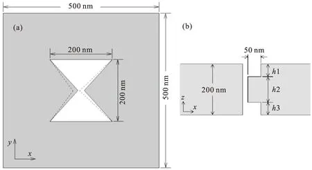
Fig.1 (a) Bowtie nano-aperture (BNA) in x-y plane.The outline length of the aperture is 200 nm.The length of the square cross section is 500 nm.Dashed line represents the aperture after gap displacement.(b) BNA with two parts of right edge cut off viewed in x-z plane.The cut length along x directiondis 50 nm.h1 andh3 are the height of the two cut parts,respectively.h2 is the height of the remaining part
3 Results and Discussions
3.1 Transmission properties of a typical BNA structure
Figure 2 is the transmission spectrum of a BNA structure with 50 nm gap.From this figure,we can see that there are three distinguishable peaks on the spectrum.The peak in the near infrared region corresponds to the fundamental resonance.At this resonant mode,the E-field enhanced area is uniform alongzdirection in the gap.It is equivalent to the mode at cutoff wavelength of an equivalent infinitely long waveguide with same profile as BNA[9].The resonant wavelength of fundamental mode is independent of film thickness and is linearly dependent of aperture perimeter[8].The peak located at about 615 nm is the Fabry-Perot-like (FP) resonance whose resonant wavelength is determined by film thickness.We refer to this resonance as FP-1 resonance since there is only one node in the center of the cavity.The two resonances we mentioned here belong to localized resonant mode.The third peak on the spectrum at 500 nm corresponds to the Rayleigh-Wood anomaly (RWA) phenomenon.It is inherently extended surface mode.Both the localized mode and extended surface mode can be identified on a typical nano-structure that exhibits extraordinary optical transmission[12].
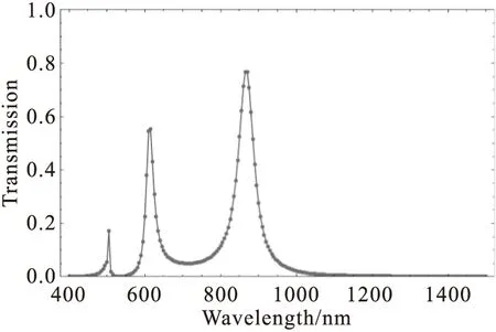
Fig.2 The transmission spectrum of BNA with 50 nm gap size.The peak at 865 nm corresponds to the fundamental resonance.The peak at 615 corresponds to the Fabry-Perot-like resonance.The peak at 505 is attributed to Rayleigh-Wood anomaly (RWA)
3.2 Displacing gap
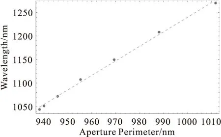
Fig.3 The linear relation of fundamental resonant wavelength with aperture perimeter of 20 nm gap size BNA.The aperture perimeter is changed due to gap displacement.The dots represent the data obtained from our simulations.The gray dashed line is the linear fitting of the actual data
The FP peaks also red-shift with increasing gap displacement.However,its changing range is not large compared to fundamental peak.For a typical BNA,i.e.20 nm gap,the changing range of FP resonant wavelength is only 56 nm,while the fundamental one can reach 226 nm.Like the fundamental resonance,the FP resonant wavelength can also be well fitted quadratically.But no obvious pattern is discovered among these fitted curves.
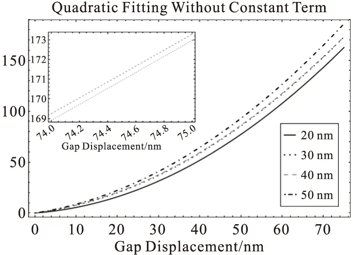
Fig.4 The curves are quadratic fittings with constant terms dropped.The curves in the figure correspond to gap sizes of 20,30,40,and 50 nm,respectively.The curve that grows faster with gap displacement indicates that the BNA is more sensitive to gap displacement.Note that the two curves that correspond to 30 and 40 nm gap are very close to each other.The inset shows a closer look at these two curves from 74 to 75 nm gap displacement
It is also worth noting that besides the peaks that correspond to fundamental,FP,and RWA resonance,there are also two small peaks in between RWA and FP peak as shown in figure 5.These two peaks appear when both large gap and large displacement are introduced.The peak near RWA peak,once appears,remains at 550 nm while the other one changes its position with displacement of gap.The wavelength of the peak near RWA peak coincides with the FP resonant wavelength of square aperture of 200 nm length (555 nm resonant wavelength).Figure 6 demonstrates the case of maximum displacement for BNA of 75 nm gap size.One node is present in the middle,indicating a FP resonance pattern.Since the field pattern is FP-like and the resonant wavelength is the same as that of the square aperture,we attribute this peak to the FP resonance of square hole.As we know,when the displacement steadily grows larger,the left edge gradually flattens and becomes more like the wall of square aperture.When one side approaches the wall of a square aperture,its characteristic resonance starts to appear.However,there is one difference that the enhanced E-field extends more to the front and rear surface than the square aperture case due to the influence of the right sharp edge.
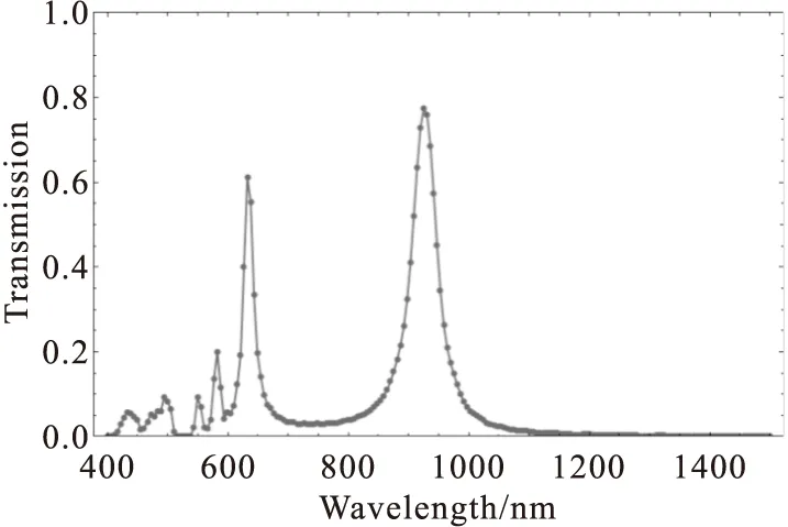
Fig.5 The transmission spectrum of BNA of 75 nm gap size and of maximum gap displacement.Two additional peaks (at 550 and 582 nm) appear between RWA peak and FP peak
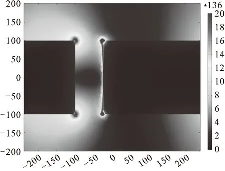
Fig.6 The E-field distribution on x-z plane.The BNA is of 75 nm gap size and of maximum gap displacement.The resonant wavelength of this distribution of field is 550 nm.This wavelength is the same as the FP resonant wavelength of square aperture array
The other peak near FP resonant peak varies with gap displacement for a fixed gap size.Figure 7 is the energy flux density distribution in x-y plane.From this figure,we can clearly observe the enhanced field intensity at two right corners.Large displacement of gap directly leads to acute angles of the two corners.As it has been studied that apertures with acute angles can give rise to another strongly localized resonance -- channel plasmon resonance (CPR)[14].The field of CPR is highly confined at the corner area.And its resonant energy is highly dependent of the angle of corner.When the gap displacement grows larger,the sharp corners start to take effect and finally lead to the presence of another resonance mode that manifests itself as another peak on the transmission spectrum.
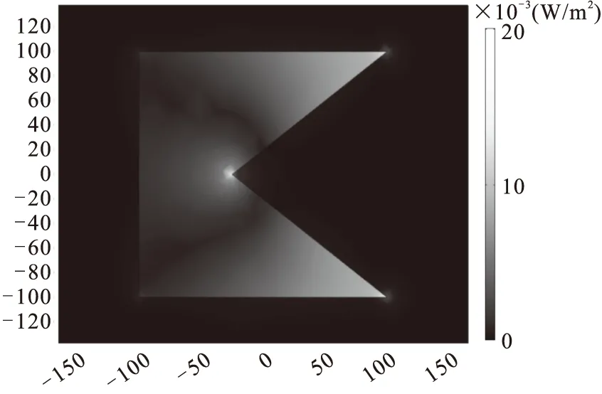
Fig.7 Energy flux density distribution of x-y plane at 582 nm resonance.The gap size is also 75 nm and displacement reaches maximum.One can view that the energy is mainly tunneled through sharp corner area and the right gap edge.This resonance is related to channel plasmon resonance (CPR) and is dependent of the angle of sharp corners
However,we emphasize again that square hole′s FP resonance and CPR only take place when there is a large displacement of gap.Because displacement leads to flattened edge and sharp corners which are the necessary causes for square hole′s FP resonance and channel plasmon resonance,respectively.
As we have discussed above,displacing the gap breaks the symmetry with respect to y-z plane and the change of fundamental resonance can be simply understood through change the electric charge oscillation path,though corner effect should be taken into account in order to have a more precise insight into the change of resonant wavelength.For the FP resonance,the charges are mainly centered at two gap edges.With that being said,we mean that the resonance is influenced by both the geometries of two edges.The modification of resonance by geometry change is more complex than that of fundamental resonance.But the resonance of two modes can be both well fitted into quadratic relation,which makes it predictable for other resonant wavelengths when several wavelengths for their corresponding gap displacement are already known.
3.3 Cutting one edge
The strategy of breaking the symmetry by displacement of gap is a simple and effective way of modifying BNA structure′s two main resonances.However,change of FP resonance is not quite impressive and its changing pattern is not regular.This irregularity of change indicates that this strategy,though simple as it seems to be for fundamental resonance,may not be an effective way to reduce the complexity in manipulating FP resonance.Perhaps the most effective way to change the FP resonance is just to use a film of different thickness.Changing the film thickness is equivalent to changing the cavity length for FP resonance,hence the change of FP resonant wavelength.And this approach can also isolate the manipulation of FP resonance from that of the fundamental resonance,since fundamental resonance is irrelevant to film thickness.This method apparently does not involve any symmetry breaking.We then question,is there any other way to modify FP resonance by other symmetry breaking strategy? We know that FP resonance is essentially due to the charge oscillation on two gap edges along z direction.And the resonance is defined by two gap edges as a whole.Thus altering the geometry of one edge should be effective.We further investigate the influence of breaking symmetry along z direction on one gap edge.
Figure 1 (b) presents the changed geometry viewed in x-z plane.Two parts of right edge are cut off.The length of the cut part alongxdirection d is 50 nm.The height of top and bottom parts cut off areh1 andh3,respectively.The height of the remaining part ish2.his the thickness of the film:h=h1+h2+h3.
We first seth2 to be 50 nm and keep it constant while increaseh1 from 0 to 75 nm.With increasingh1 and constanth2,the remaining block on the cut edge moves from top to center,gradually restoring the symmetry with respect to x-y plane.Note that,according to our simulation results (not shown here),whether illuminated from top or from bottom,the structure we study in this section has the same transmission spectrum.Thus,it is sufficient to stoph1 at 75 nm.Figure 8 (a) depicts the transmission spectra for differenth1 which is represented by y axis.From the spectra,we can see that the position of the fundamental peak remains unchanged with increasingh1 while FP resonance splits into two peaks.The FP peak of longer wavelength gradually blue-shifts with increasingh1 and finally merge into the other FP peak whenh1 grows large enough.The position of the FP peak of shorter wavelength,surprisingly,does not change at all withh1.
To understand the different dependence of the three resonant peaks mentioned above on geometry,we studied another case.In this case,we gradually decreaseh2 while always keepsh1 equals toh3.For convenience,we refer to this case as symmetric case since the symmetry with respect to x-y plane is maintained.And we refer to the case studied above in this section as asymmetric case.The result is shown in figure 8 (b).Thexaxis represents wavelength and the y representsh1.We can see from this figure that the position of fundamental resonance changes linearly withh1 and apparently also withh2.Comparing to the previous case in which the resonant position does not change whenh2 is kept constant.We can conclude that the wavelength of fundamental resonance is linearly connected withh2.As for FP resonance,different from the previous case where there is a peak split,a gradual transition from one FP resonance to the other can be observed.Whenh1 is zero,the aperture is a common BNA (20 nm gap size) whose FP resonant wavelength is 665 nm.Then,with increasingh1,this peak starts to blue-shift.Whenh1 becomes larger than 40 nm,the peak position stops changing and remains constant at about 610 nm.
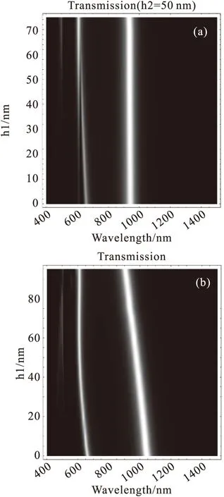
Fig.8 Transmission spectra of structures for two cut-edge approaches.(a)h2 is kept 50 nm.The position of fundamental peak remains constant,while FP peak splits into two separate peaks.(b)h1 is kept equal toh3 in this case.With increasingh1 (also decreasingh2),the position of fundamental peak changes linearly,while the FP peak experiences a gradual transition
In the extreme case whereh2 is zero,the FP resonant wavelength is 610 nm.This wavelength is exactly the same as the FP resonant wavelength that is irrelevant toh2 in the second case whenh1 is larger than 40 nm.Thus,we categorize this resonance as FP resonance.We know that for a typical BNA structure,its FP resonance is inherently due to the local charge oscillation along two gap edges.In the all cases we study in which the film thickness is 200 nm,there is only one FP resonant peak can be observed in the transmission spectrum.And this resonance should be named FP-1 resonance to reveal its resonant pattern since there is one node in the center of the cavity.In order to distinguish two different FP resonances,we refer to the resonance which changes withh1 as FP-1-1 resonance and the other which remains at 610 nm as FP-1-2 resonance.When the resonant condition is satisfied,two semi-circle-like charge oscillation paths are formed on two edges.This pair of paths,which do not go directly straight up or down along the edges,leads to the immunity to geometry change at the center area in the gap.This is the reason why FP-1-2 peak remains constant whenh1 increased beyond 40 nm in the symmetric case.Whenh1 is smaller than 40 nm,the remaining block of lengthh2 interferes with the resonance defined by the two paths and consequently modifies the resonance.This influence by the remaining block is manifested by the dependence of FP resonance onh1.This theory can also explain the phenomenon that there is a gradual energy transition between FP-1-1 and FP-1-2 peaks in the asymmetric case.With increasingh1,the remaining block changes its position from top to the central part the gap,reducing its influence on FP-1-2 resonance and consequently the intensity of FP-1-2 peaks steadily grows.
Another point worth noting is that,as shown in figure 8 (b),the change of position of fundamental peak withh1 is gradual and smooth in the symmetric case.This is because the fundamental resonance is dominated by the remaining block on the right edge as well as part of the left edge.However,whenh2 turns 0 nm,there is no remaining block in the gap any more,the resonance is suddenly handed over to the new structure.This structure,withh2=0,is essentially different from the structure with remaining block on its right edge.Because the current density is uniformly distributed alongzdirection,which is why the fundamental resonance of this kind of structure is independent of film thickness.In the case whereh2 is not zero,since the current density is mainly concentrated in the area of the remaining block,the fundamental resonance is highly dependent onh2,as we have shown above.
4 Conclusions
We proposed two simple approaches to breaking the symmetry in order to manipulate both of BNA′s fundamental and Fabry-Perot resonant peaks for extraordinary optical transmission.Both approaches show interesting results.With displacing the gap of BNA,one can predictably change the fundamental peak based on the linear relation with aperture perimeter.Using cut-one-edge method,one has the great flexibility in changing the fundamental resonance in linear fashion and altering the FP resonance in a predictable way.Our research can be applied to help to design better optical filters and other applications to meet a large array of possible needs.
[1] Ebbesen T W,Lezec H J,Ghaemi H F,etal.Extraordinary optical transmission through sub-wavelength hole arrays[J].Nature,1998,391:667-669.
[2] Shao Weijia,Xu Xiaoliang,Wang Huijie.A manipulated extraordinary optical transmission filter composed with subwavelength hole complex arrays[J].Plasmonics,2014,9:1025-1030.
[3] Ruan Zhichao,Qiu Min.Enhanced transmission through periodic arrays of subwavelength holes:the role of localized waveguide resonances[J].Phys Rev Lett,2006,96:233901.
[4] Wang Yongkai,Qin Yan,Zhang Zhongyue.Extraordinary optical transmission property of X-shaped plasmonic nanohole arrays[J].Plasmonics,2014,9:203-207.
[5] Rodrigo S G,Mahboub O,Degiron A,etal.Holes with very acute angles:a new paradigm of extraordinary optical transmission through strongly localized modes[J].Opt Express,2010,18:23691-23697.
[6] Lin L,Roberts A.Light transmission through nanostructured metallic films:coupling between surface waves and localized resonances[J].Opt Express,2011,19:2626-2633.
[7] Degiron A,Ebbesen T W.The role of localized surface plasmon modes in the enhanced transmission of periodic subwavelength apertures[J].J Opt A:Pure Appl Opt,2005,7:S90-S96.
[8] Guo Hongcang,Meyrath T P,Zentgraf T,etal.Optical resonances of bowtie slot antennas and their geometry and material dependence[J].Opt Express,2008,16:7756-7766.
[9] Ibrahim I A,Mivelle M,Grosjean T,etal.Bowtie-shaped nanoaperture:a modal study[J].Opt Lett,2010,35:2448-2450.
[10] Kinzel E C,Xu Xianfan.Extraordinary infrared transmission through a periodic bowtie aperture array[J].Opt Lett,2010,35:992-994.
[11] Yin Xiaogang,Huang Chengping,Shen Zhiqiang,etal.Splitting of transmission peak due to the hole symmetry breaking[J].Appl Phys Lett,2009,94:161904.
[12] Carretero-Palacios S,Garcia-Vidal F J,Martin-Moreno L,etal.Effect of film thickness and dielectric environment on optical transmission through subwavelength holes[J].Phys Rev B,2012,85:035417.
[13] Huang Chengping,Wang Qianjin,Zhu Yongyuan.Dual effect of surface plasmons in light transmission through perforated metal films[J].Phys Rev B,2007,75:245421.
[14] Moreno E,Garcia-Vidal F J,Rodrigo S G,etal.Channel plasmon-polaritons:modal shape,dispersion,and losses[J].Opt Lett,2006,31:3447-3449.
非对称领结型纳米孔阵列的光透射特性
孙鑫,冯敏,王斌,曹学伟,王玉芳*
(南开大学物理科学学院,天津 300071)
本文利用数值模拟的方法研究了两种不同的非对称领结型纳米孔结构的光学特性。对于偏置间隙的领结型纳米孔,其基模共振与孔的周长呈线性关系。并且,不同的间隙尺寸对间隙偏置的敏感度不同。对于间隙的一边的结构发生变化的领结型纳米孔,基模共振可以通过改变单个几何参量(剩余部分的高度h2)进行线性调制。另外,研究中还观察到了类Fabry-Perot共振的共振峰分裂。我们在这项工作中提出的这两种打破领结型纳米孔的对称性的方法可以灵活地对领结型纳米孔结构的共振进行操控。
领结型纳米孔;异常光透射;表面等离子体基元;光学共振
2015-08-10; 修改稿日期:2015-09-20
孙鑫(1990-),男,硕士,主要从事微纳光学、光透射增强研究.E-mail:sunxin_mail213@126.com
王玉芳.E-mail:yfwang@nankai.edu.cn
1004-5929(2016)03-0285-08
O43
A
10.13883/j.issn1004-5929.201603016
猜你喜欢
汽车实用技术(2022年15期)2022-08-19
中国信息化(2022年5期)2022-06-13
装备制造技术(2020年4期)2020-12-25
太原科技大学学报(2019年3期)2019-08-05
航天电子对抗(2019年4期)2019-06-02
知识经济·中国直销(2018年12期)2018-12-29
当代陕西(2018年12期)2018-08-04
电子制作(2017年13期)2017-12-15
北京航空航天大学学报(2016年6期)2016-11-16
中国卫生(2014年9期)2014-11-12