
Study on co-simulation model of forging manipulator based on virtual prototyping①
2016-12-05 01:27ZhaiFugang翟富刚ZhuHanyinWuQileiKongXiangdong
High Technology Letters 2016年2期
Zhai Fugang (翟富刚), Zhu Hanyin*, Wu Qilei* , Kong Xiangdong
(*School of Mechanical Engineering, Yanshan University, Qinhuangdao 066004, P.R.China) (**Key Laboratory of Advanced Forging & Stamping Technology and Science (Yanshan University),Ministry of Education of China, Qinhuangdao 066004, P.R.China) (***Hebei Provincial Key Laboratory of Heavy Machinery Fluid Power Transmission and Control,Yanshan University, Qinhuangdao 066004, P.R.China)
Study on co-simulation model of forging manipulator based on virtual prototyping①
Zhai Fugang (翟富刚)***, Zhu Hanyin****, Wu Qilei****, Kong Xiangdong②******
(*School of Mechanical Engineering, Yanshan University, Qinhuangdao 066004, P.R.China) (**Key Laboratory of Advanced Forging & Stamping Technology and Science (Yanshan University),Ministry of Education of China, Qinhuangdao 066004, P.R.China) (***Hebei Provincial Key Laboratory of Heavy Machinery Fluid Power Transmission and Control,Yanshan University, Qinhuangdao 066004, P.R.China)
Based on the characteristics of integrated virtual prototype technology, the mechanical system sub-model, the hydraulic system sub-model and the control system sub-model of a forging manipulator system have been built using a variety of software, and a forging manipulator multidisciplinary co-simulation model has been also built using a method of simulation models interface. Then the simulation and experiment are finished, and the result of the experiment is in good agreement with the result of the simulation. It shows that the co-simulation model established can simulate accurately parameter changes in real time during the moving of the forging manipulator such as displacement, velocity and pressure flow, which is of important significance for the optimized design of the forging manipulator system to establish the models.
forging manipulator, virtual prototype, co-simulation, control characteristics
0 Introduction
A forging manipulator is a major auxiliary equipment to realize mechanisation and automation in forging workshops[1]. It is mainly used for clamping forgings to finish cogging, upsetting, stretching and other forging processes cooperating with the press, which can increase labor productivity and improve quality of the product and reduce labor intensity[2]. In recent years, the hydraulic forging manipulator has become the mainstream of development because of compact structure, smooth working condition and convenient operation. However, with the improvement of requirements for forging process, the hydraulic forging manipulator should have more action and function, such as tongs tilting, tongs side-shifting, tongs suspension[3]. The complexity of mechanical structure of forging manipulator leads a more complex hydraulic and control system, which has become a research hotspot and difficulty[4].
Modeling is the first step of simulation research, which determines the accuracy of the simulation results. As a whole, the forging manipulator is a system which contains mechanical, hydraulic, electric control and so on. But unfortunately, most scholars ignore the link between them when modeling research[5], that leads to poor results accuracy. The virtual prototyping (VP) is the rise of a computer aided engineering technology in the 20th century[6]. Although the core is the theory of kinematics and dynamics, the VP is not limited in application of machinery. It also includes the synthesis of many subjects such as geometric modeling, structure analysis, hydraulic transmission, electric control and so on. Since of dynamic characteristics of virtual prototype is completely close to the physical prototype, the VP has been widely used in automotive, aerospace, machinery etc. and gets huge benefits[7]. In view of this, this study aims to build a co-simulation model of forging manipulator based on VP, which includes sub-models of the mechanical system, the hydraulic system and the control system. It can play an important role for complex system modeling and optimization design of forging manipulator system.
1 Physical prototype of forging manipulator
The physical prototype is the basis of virtual prototype model. In this study, a capacity of 200kN/500kN.m forging manipulator is selected as physical prototype, shown in Fig.1. The parts of the hydraulic and electric control system are installed at the tail. The forging manipulator can perform seven movements, such as vehicle driving, tongs clamping, tongs rotation, tongs lifting, tongs tilting, tongs shifting and tongs swing. It is important to note that its center of gravity changes with the movement of actuator, that is the reason of virtual prototype built. As Fig.2 shows that a variety of hydraulic cylinders and motors are used to drive these actuators, which connect mechanical system and hydraulic system of the forging manipulator.
There are several valves controlling the hydraulic cylinder or motor accordingly, which link the hydraulic system and the control system.

Fig.1 The 200kN/500kN.m forging manipulator

1.bump 2.unloading relief valve 3,23.accumulator 4,7,10,14,26.relief valve 5.filter 6. auxiliary pump 8,12,16,19,21.directional valve 9,25.proportional valve 11,27.motor 13,22.pilot operated check valve 15,18,20,24.cylinder 17.balance valve Fig.2 The schematic diagram of the hydraulic system
2 Co-simulation model of forging manipulator
Since the characteristics of virtual prototype are close to physical prototype, a co-simulation model needs to be established, which includes 3D geometry model, mechanical system sub-model, hydraulic system sub-model and control system sub-model. The relationship between these sub-models is shown in Fig.3. It can be seen that the 3D geometry model includes geometric parameters and material properties, which is a virtual device and used to show the movement of physical prototype in computer with visualization. Because of the complexity of the machinery, the sub-model of mechanical system is a multi-dynamics sub-model composed of lots of dynamics and kinematics equations, and the sub-model of hydraulic system is made up of a series of pressure and flow equations. As a connected component, the hydraulic cylinder (or motor) is used to provide force (or torque) for mechanical system sub-model, and the displacement of hydraulic cylinder (or motor) is used to solve the pressure and flow equations in real-time. And the sub-model of control system provides action signals for the valves in the hydraulic system to control motion trajectory and state of the forging manipulator. The parameter coupling relation is the basis to solve the co-simulation model of the forging manipulator.
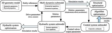
Fig.3 The parameter coupling principle between models
2.1 Mechanical system modeling of the forging manipulator
First of all, according to the engineering graphics of M-200kN/500kN, the 3D geometry model of forging manipulator is built in Pro/E, which is given to the entity information, including material density and physical properties. It also needs to import the 3D geometry model into the ADAMS (automatic dynamic analysis of mechanical system) environment to set dynamics properties, including constraint relation, applied stress, friction setting, etc. Finally, the mechanical system model of the forging manipulator is established, shown in Fig.4. As is shown, the driving wheel of cart is driven by a chain wheel on the sprocket track fixed on the ground. The gear pair is arranged between the chain wheel and the chain wheel track, and the rotation pair with dynamic friction coefficient of 0.01 and static friction coefficient of 0.02 is set between the wheels and the vehicle. The wheels walking on the tracks only play a supporting and guiding function. And the kinematic constraint of the other parts are set up according to the movement relationship of the component. In this paper, a total of 41 kinematic constraints are set up for the mechanical system sub-model of the forging manipulator, which can realize operation of all seven motions and the function of simulation.
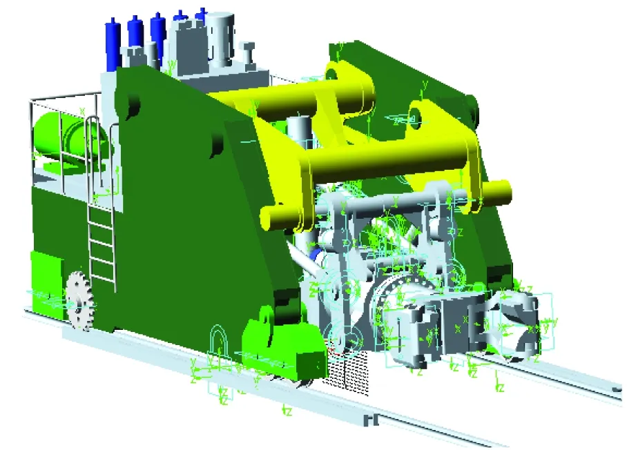
Fig.4 Mechanical system sub-models of forging manipulator
2.2 Co-simulation model of the forging manipulator
The nature of co-simulation is interconnection and interoperability of multi-discipline domain models[8]. The co-simulation is based on the unified language or the model interface. The co-simulation method based on the unified language is to establish multi-disciplinary field co-simulation with the unified language in the same software flat and adopt the same solver to solve the system. Hower, this method is not yet mature for all kinds of models and needs to be developed in order to meet the requirements of actual modeling and simulation. A method is adopted that the co-simulation is based on interface model to build the multi-disciplinary field co-simulation model, as shown in Fig.5. The hydraulic system and control system are built in AMESim (advanced modeling enviroment for performing simulation of engineering systems) environment, and all sub-models call information data of the mechanical system sub-model stored in the internal interface model to complete real-time data transmission and interaction.
The model interface is the data channel of the multi-disciplinary co-simulation. The left of the interface shows driving parameters of the mechanical system, among which , XM1、XM2、ZM1、ZM2、SF1、SF2、XF1、CF1、CF2 and JF1 represent the driving torque of the rotating motor(number:2), the driving torque of the walking motor(number:2), the driving force of the lifting cylinder(number:2), the driving force of the tilting cylinder, the driving force of the side-shifting cylinder(number:2) and the driving force of lamping cylinder respectively. The right of the interface shows the motion parameters of the mechanical system, and the suffix _w、_v、_xrepresents rotating speed, speed and displacement of the corresponding components respectively. When the co-simulation runs, the mechanical system sub-model calculates the motion parameters equivalent to actuator automatically in different pose and load conditions of the forging manipulator and passes the data to the hydraulic system model. so the dynamic changing in the process of forging manipulator can be simulated in real time, which makes the simulation result more accurate and closer to the actual working condition. In addition, the motion trajectory and state can reappear and be monitored by calling ADAMS with 3D visualization function through interface settings. The main parameters of the co-simulation model of the forging manipulator are shown in Table 1.

Table 1 The main parameters of the co-simulation model of the forging manipulator

Fig.5 Forging manipulator co-simulation model
3 Verification of the co-simulation model
The method of verification is based on the data collected from the experiment test of physical prototype of the forging manipulator. In the same environment and conditions, the same signals as what is given in experiment are input to the co-simulation model. Comparing the simulation results obtained by the virtual test with the experimental results, the accuracy of the model is verified.
The same environment is that the working medium and oil temperature in virtual test are the same as what are in the experiment test. In the virtual test, the oil temperature is set up to 20℃ and the working medium of the system is L-HM46 hydraulic oil. The medium property is set up as follows: oil density is 890kg/m, volume elastic modulus is 1650MPa, saturated steam pressure is 9.85kPa, gas content is 0.9% and motion viscosity is 46mm2/s(40℃). The same conditions mainly refer to the initial position of the mechanical system of the forging manipulator, the initial parameters of the hydraulic system and the given signal of the control system.
The simulation and experimental curves of the walking motion are obtained,as is shown in Fig.6. In the figure,xrepresents the displacement of cart , v1represents the speed of cart,Srepresents the control signal given to the control valves, “100%” shows that the control valve is fully open, “0” shows that the control valve is close. It is clear that the error of the steady state value of walking displacement of cart is only 2mm under the experimental test with the value is 238mm and the simulation test with the value is 240mm, and the location accuracy reaches 99%. As is shown in Fig.6(b), the simulation curve of the walking speed of the whole trip is basically consistent with the experimental curve, which shows that the simulation model can be used to simulate the dynamic changes of the forging manipulator during walking.
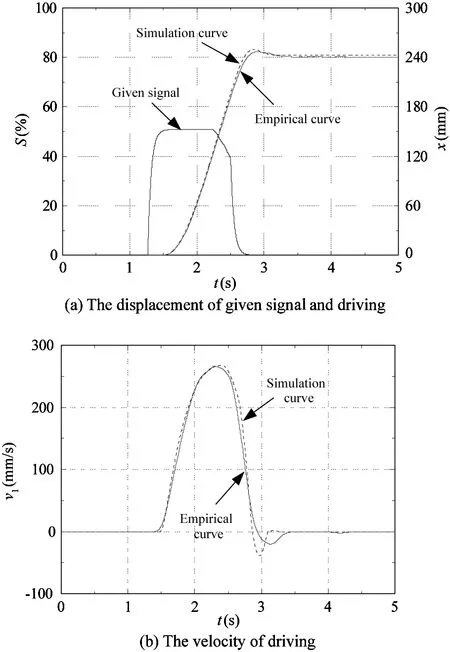
Fig.6 The simulation and experimental curve of walking cart
The co-simulation model of the forging manipulator can not only simulate the motion trajectory and motion state of the actual physical model, but can also simulate the pressure and flow changes of the hydraulic system during the motion process, as is shown in Fig.7.
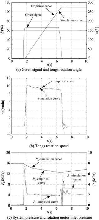
Fig.7 The simulation and experimental curve of rotating clamp
In Fig.7,αrepresents the angle of rotating tong,wrepresents the rotating speed of tong, P0represents the system pressure, and P1represents the inlet pressure of the rotating motor. It can be seen that the four-group simulation curves in the synchronous test are basically consistent with the experimental curves in the same given signal condition, and the location accuracy reaches 99%. At the same time, the co-simulation can simulate the pressure changes of hydraulic system of manipulator tongs well in the process of rotary motion, which is of important significance for studying the hydraulic control system of the forging manipulator.
Hydraulic principle of clamp down action is relatively simple for that the action is completed under the self gravity and the rate of decline is controlled only by return throttle. So only the model of parallel lifting action is verified in this paper as is shown in Fig.8. In the figure, y represents the displacement of the clamp parallel lifting, v2represents the speed of clamp parallel lifting, P2represents working chamber pressure of the lifting cylinder. The curves are obtained under light load mode while the system pressure is 14MPa. As can be seen, steady displacement of parallel lifting clamp in experimental test is 1182mm, the result of virtual simulation test in the same condition is 1189 mm, so the degree of matching of displacement curve is good. As shown in Fig.8(c), due to the large
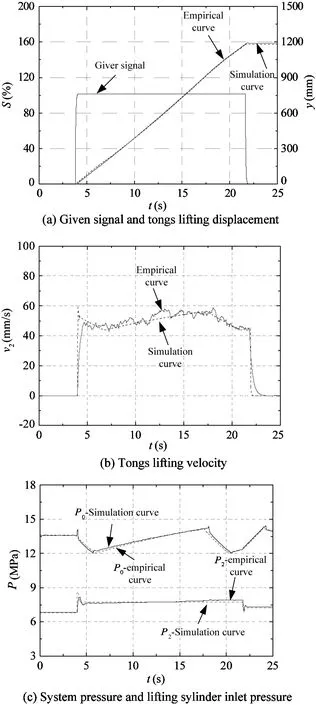
Fig.8 Clamp parallel lift simulation and experimental curves
clamp vertical stroke, a lot of oil is needed. When the system pressure drops to the loading pressure point set by the electromagnetic unloading relief valve, the main pump supplies the oil to the loading system, so the system pressure increases. Conversely, when the system pressure rises to what the electro-magnetic unloading relief valve has set, the main pump is unloading, and the accumulator provides oil to the system alone. So the system pressure drops. In the promotion process of clap, elevating cylinder pressure is maintained at about 7.7MPa to balance its own gravity and motion friction. Compared with the 4 group simulation curves and experimental curves, it can be seen that the simulation and experimental curves of tongs lifting agree well, which shows the simulation model of the forging manipulator established has high accuracy.
4 Conclusions
Based on virtual prototyping technology, a multi-discipline co-simulation model is established. The model is integrated with the multi-body dynamics solving module, hydraulic system and control system solving module. It can not only study the motion trajectory and motion state, but also study the characteristics of the hydraulic control system of forging manipulator. The establishment of co- simulation model has important significance for the optimization design of the forging manipulator system.
The simulation model of the forging manipulator is verified by quantitative verification method. The simulation and experiment are finished, and the curves of the displacement, velocity and pressure of the synchronous test in simulation are basically consistent with the experimental curves. The results show that the co-simulation model has high accuracy, which lays the foundation for the application of the co-simulation model.
Reference
[1] Nowitzki W. Manipulators with mass division increase throughput and save energy in high-precision forging.MPTMetallurgicalPlantandTechnologyInternational, 2008, 31(5): 46-48
[2] Chen K, Ma C X, Zheng M Q, et al. Optimization and mechanical accuracy reliability of a new type of forging manipulator.ChineseJournalofMechanicalEngineering(EnglishEdition), 2015, 28(2): 236-248
[3] Xu Y D, Liu Y, Yao J T, et al. Analysis of a novel lifting mechanism for forging manipulators.ProceedingsoftheInstitutionofMechanicalEngineers,PartC:JournalofMechanicalEngineeringScience, 2015, 229(3): 528-537
[4] Tarja T, Asko E, Taina K. Virtual prototypes reveal more development ideas: comparison between customers' evaluation of virtual and physical prototypes: This paper argues that virtual prototypes are better than physical prototypes for consumers-involved product development.VirtualandPhysicalPrototyping, 2014, 9(3): 169-180
[5] Ren Y P, Han Q K, Zhang T X, et al. Dynamic simulation of forging manipulator based on virtual prototyping.JournalofNortheasternUniversity, 2010,31:1170-1173
[6] Tong X X. Research of buffer equipment in forging manipulator based on virtual prototyping technology.Equipment, 2010, 4:46-48
[7] Tie M, Fan Y S. HLA based multidisciplinary collaborative simulation framework for forging and manipulating process.LectureNotesinComputerScience, 2008,5314:1256-1264
[8] Fu Y L, Qi X Y. AMEsimSystem Modeling and Simulation. Beijing: Beijing University of Aeronautics and Astronautics Press, 2006
Zhai Fugang, born in 1979, Ph.D, assistant professor, party branch secretary of the Department of Mechanical Design of Yanshan University. The primary area of research are mechanical-electrical hydraulic integration of fluid simulation, mechanical design, and heavy mechanical power transmission and control. He has published over 10 academic papers, among which there are 4 papers indexed by SCI, EI, ISTP, authorized 2 patents, and participated in more than 10 national and provincial-ministerial research projects.
10.3772/j.issn.1006-6748.2016.02.003
①Supported by the National Natural Science Foundation of China (No. 51575471), and Collaborative Innovation Program Topics of Heavy Machinery of Yanshan University (2011 Program, No. ZX01-20140400-01).
②To whom correspondence should be addressed. E-mail: xdkong@ysu.edu.cnReceived on May 7, 2015
 High Technology Letters2016年2期
- High Technology Letters的其它文章
- Buffer allocation method of serial production lines based on improved ant colony optimization algorithm①
- Bionic jumping dynamics of the musculoskeletal leg mechanism for quadruped robots①
- Evaluation of cable tension sensors of FAST reflector from the perspective of EMI①
- Removal of jamming using independent component analysis in non-cooperative passive detection system①
- A cooperative user selection scheme based on energy efficiency and interference factor in cooperative communication systems①
- Abnormal activity detection for surveillance video synopsis①