
Design and experiment of the centrifugal pump impellers with twisted inlet vice blades *
2017-03-14 07:06HongxunChen陈红勋JianwuHe何建武ChaoLiu刘超
水动力学研究与进展 B辑 2017年6期
Hong-xun Chen (陈红勋), Jian-wu He (何建武), Chao Liu (刘超)
Shanghai Institute of Applied Mathematics and Mechanics, Shanghai University, Shanghai 200072, China,E-mail: chenhx@shu.edu.cn
Since gap drainage impeller has been put forward,the author and his collaborators have carried out a series of research[1-7]. In terms of the design of gap drainage impeller, the optimized design process of vice blades are explored, as a preliminary. For the research into mechanism, a scalable detached simulation(SDES)[4]model was proposed and developed based on the detached eddy simulation (DES)[8]method.
By numerical analysis based on SDES model and flow visualization experiments[4], it was considered that the leading edge deviating from original position reduced the blade exclusion and the vice blades overlapping partly with main blades increased the inlet flow channel area. This made flow velocity field distribution more uniform to reduce the energy loss, as can be seen in Fig.1.
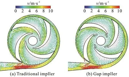
Fig.1 (Color online) Water velocity distributions[4]
In addition, the separated flow would be suppressed at the leading edge as a result of guide flow function of the vice blades of gap drainage impellers,and high pressure fluid on the pressure surface passes through the gap into the suction surface which compensates pressure to low pressure zones to some extent. At the same time, the fluid ejected from the gap produces a disturbance to the cavitation region,which accelerates the cavity shedding and suppresses the formation of large cavitation area to improve the cavitation performance, as are illustrated in Fig.2.
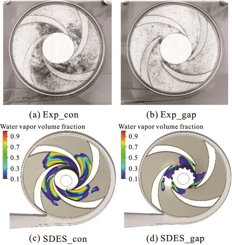
Fig.2 (Color online) Water vapour volume[4]
Based on theoretical analysis, numerical simulation and PIV flow field tests, the mechanism how gap drainage impellers improve hydraulic performance and cavitation performance of low specific speed centrifugal pumps has been deeply studied. Furthermore, the measurement of pressure pulsation and vibration was carried out at inlet, outlet and volute zone of centrifugal pumps with gap impellers under cavitation and non-cavitation conditions. It was found that gap drainage blades also improve the dynamic characteristics of centrifugal pumps in a certain range of conditions.
Currently, gap drainage technology is mainly used for cylindrical blades. In order to introduce gap drainage technology into practice widely, the twisted vice blade should be studied based on the above physical mechanism. The profile of the vice blade at leading edge and relative position of main blade need to be parameterized, and the influence of these parameters on the performance of a centrifugal pump should be explored. The essence of spatial geometric expression for a traditional centrifugal impeller is to calculate geometric parameters according to performance parameters, draw main streamlines to determine the working surface of blade, and then obtain the whole blade by thickening surface based on a certain law.
Compared with a traditional impeller, a gap impeller has a short blade at the leading edge, which partially overlap and hold a gap with main blade. The vice blade usually can be designed and modified on the basis of the traditional impeller. The gap impellers have the same structure parameters as traditional impellers, which means that they are identical in meridional cross-section. The basic process of drawing the gap drainage blade can be described in Figs.3(a), 3(b).
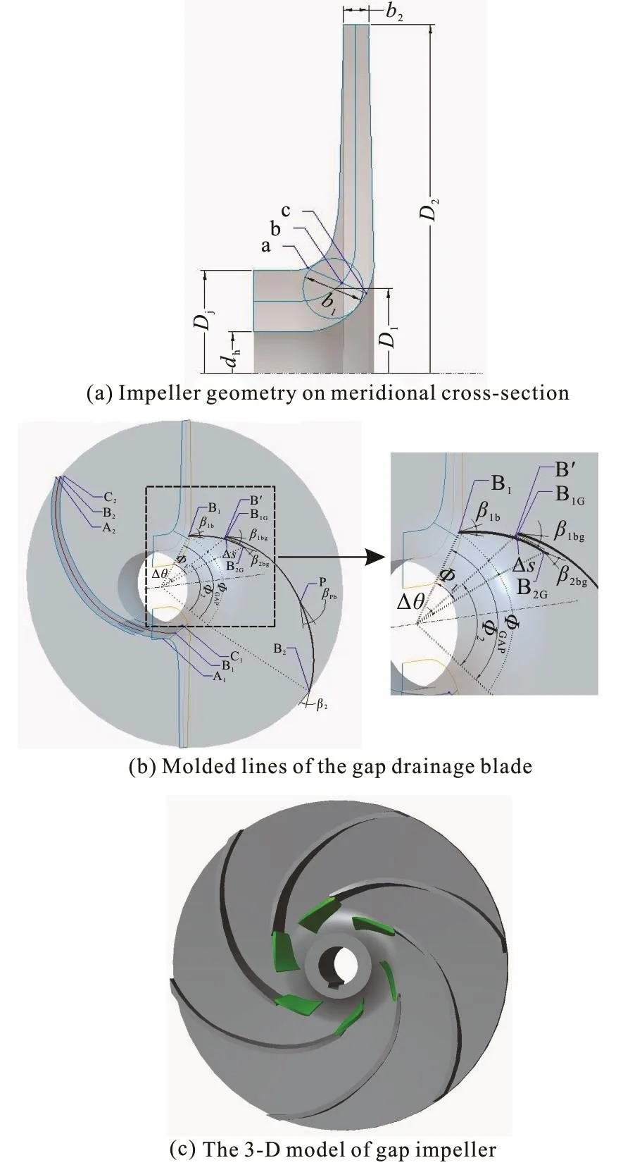
Fig.3 (Color online) Geometric drawing processofthegap drainage impeller
(1) The total wrap angle0Φ is determined by number of blades Ζ and specific speedsn. The initial inlet location points (A1, B1, C1) of the blade, as well as the outlet location points (A2, B2, C2) are obtained according to the hydraulic design method of a traditional centrifugal impeller.
(2) According to the design method of the traditional impeller, three streamlines on meridional crosssection which is starting from A1, B1and C1are drawn,and flow surfaces A, B and C are formed by rotating around the rotation axis.
(3) Inlet angle (β1a, β1b, β1c) and outlet angle(β2a, β2b, β2c) are calculated and selected properly.According to a given change rule of blade angle, three smooth streamlines are fitted on the spatial flow surface.
(4) The middle streamline is used as an example to illustrate the drawing procedure of gap drainage blades. Based on the middle blade profile drawn in Step 2, the positions that boundary layers are separated are inferred by experience. The truncation point B1Gis determined preliminarily, and molded line B1-B2is divided into two segment (B1-B1G, B1G-B2).
(5) The leading edge segment (B1-B1G) is removed, and the position of the remaining part (B1G-B2)remains unchanged. B1G-B2is defined as the middle molded line of main blade, and inlet angle1bgβ of main blade are obtained. The wrap angle corresponding to the middle molded line is defined as the wrap angle of main blade2Φ. Generally,2Φ should be less than0Φ, which means main blade is slightly shorter than entire blade designed according to traditional method.
(6) The inlet location point (B1G) of main blade along the streamline on meridional cross-section is moved to obtain the auxiliary point Bʹ. The movement distance ()sΔ should be larger than thickness of the flow surface corresponding to this point. Then the point is rotated θΔ around Ζ axis to determine the outlet location point (B2G) on the middle streamline.The intersection angle ()θΔ between the meridional planes, where B1Gand B2Glocate, is defined as the overlapping degree between vice blade and main blade that should be determined according to experience. To ensure the smooth flow, the outlet angle (β2bg) of vice blade can be determined by referring the inlet angle ( β1bg) of main blade. Depending on the actual situation, it could be made appropriate adjustments.
(7) The wrap angle of vice blade is defined as1Φ,and appropriate1Φ is selected to re-determine the inlet location point (B1) of the middle streamline and determine the inlet angle1b()β of vice blade. At this time, the total wrap angle of vice blade and main blade is defined asgapΦ.
(8) According to the given law about drawing blade profile described in Step 3, molded line B1-B2Gis drawn that be called the middle molded line of vice blade. At this point, the process of drawing the middle molded line B1- B2Gand B1G-B2have been finished.
(9) Then, the procedure for segmenting of the initial blade, re-determining of the location points and reshaping the profile of vice blade is repeated. In accordance with the principle that molded lines should be smoothly transited, the molded lines on front cover(A1-A2G,, A1G-A2) and back cover (C1-C2G, C1G-C2)of the main and vice blade are drawn respectively.
(10) The molded lines obtained by the above method are fitted to the working surfaces of main and vice blade. According to the law of thickening blades,the working surfaces are thickened to obtain the back surfaces of the main and vice blade.
Designing gap drainage blades need to determine some additional parameters (1Φ,2Φ, θΔ,gapΦ,Δs ). Currently, these parameters are mainly determined in accordance with the principle of reducing exclusion and suppressing flow separation, which are determined by designer’s experience.
On the basis of the above, a centrifugal pump impeller with good performance is designed and manufactured as shown in Fig.3(c). And the hydraulic performance and cavitation performance tests are carried out on the open loop test rig. The performance curves in Fig.4 shows that the Q-η (Q and η respectively represent the flow rate and efficiency)curve of the gap pump is overall higher than the traditional pump, which means all conditions have been improved to some extent. The Q-H (H is the abbreviation of head) curves tend to be flat at initial stages, and head of the gap pump is basically the same as the traditional one under low flow rate conditions. As flow rate increases, the Q-H curve of the gap pump moves up as a whole. That is to say,head of the gap pump is higher than the traditional one under other conditions except for low flow rate conditions. Furthermore, the gap pump’s power is widely lower than the traditional one’s, and the difference decreases as flow rate increases.
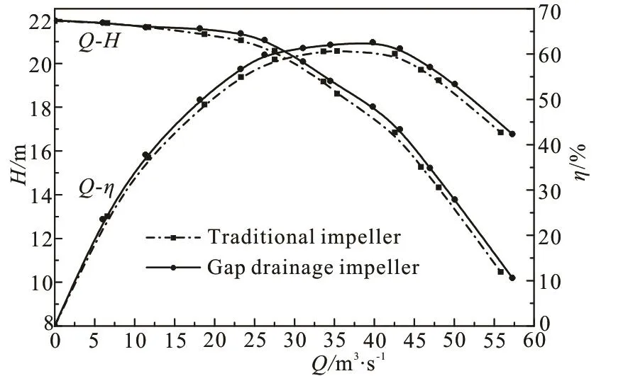
Fig.4 Performance curves of the two pumps
Flow rate of the performance curves shown in Fig.4 is replaced by specific speed (denoted bysn) as the results shown in Fig.5. It is found that compared with the traditional impeller, efficiency of the gap pump is improved under different specific speeds. And whensn is in the range from 35 to 70, the effect become more obvious.
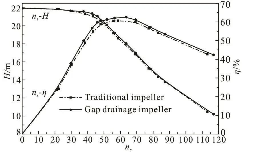
Fig.5 Specific speed-performance parameters curves
Figure 6 shows the cavitation performance curves of the two pumps at three flow rates. It can be seen that regardless of gap impeller or traditional impeller,with the net positive suction head available ( N PSHa)gradually reduced, the head curves are showing a trend from nearly straight to slow downward to steep downward under different flow rates.
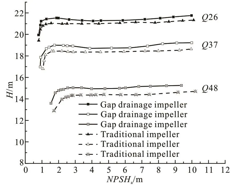
Fig.6 Cavitation performance curves of the two impellers
The working point at which pump head is reduced by 3% is regarded as the critical cavitation point, and N PSHacorresponding to this situation is defined asIt is listed that the NPSHcvalues of the two pumps under three flow rates, as shown in Table 1. It can be seen that N PSHcof gap pump is both lower than traditional pump under different flow rate conditions. With the gradual increase of flow rates, the difference between traditional pump and gap pump is also incre3asing,especially it reaches 0.37m when Q is 48m/h. It shows that during the decline of N PSHa, the time when cavitation occurs for gap pump is later than with traditional one. That means gap pump has better cavitation performance, especially in the high flow rate area, the effect is more significant.
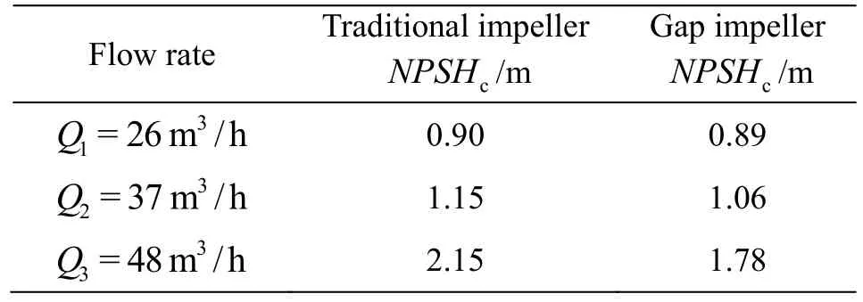
Table 1 N PSHc values of two pumps at different flow rates
In this paper, the design idea and method for the spatial geometry of twisted gap drainage blade are put forward, which develop the design method of gap drainage blade from 2-D to 3-D twisted blade and will achieve an advancement for introducing gap drainage technology into practice. It is verified that the twisted vice blades can improve the hydraulic performance and cavitation performance of the centrifugal pumps.
The influence of the geometric parameters of gap drainage blade on the performance of centrifugal pump is not entirely clear, but this work provides some new idea for the following research. It is valuable to explore the mechanism how these geometric parameters affect the hydraulic performance,cavitation performance, pressure pulsation, vibration and characteristic curves of centrifugal pump in future researches.
[1] Chen H. X., Liu W. W., Jian W. et al. Development of low specific-speed centrifugal pump impellers based on flow control technique [J]. Chinese Journal of Drainage and Irrigation Machinery Engineering, 2011, 6(9):466-470(in Chinese).
[2] Zhu B. Research on the mechanism of performance improving in low specific speed centrifugal pump with gap drainage blades [D]. Doctoral Thesis, Shanghai, China:Shanghai University, 2014(in Chinese).
[3] Zhang W. Z. Experimental research on pressure fluctuation and vibration property of centrifugal pump with gap drainage impeller [D]. Master Thesis, Shanghai, China:Shanghai University, 2016(in Chinese).
[4] Zhu B., Chen H., Wei Q. Numerical and experimental investigation of cavitating characteristics in centrifugal pump with gap impeller [J]. International Journal of Turbo and Jet-Engines, 2014, 31(2): 187-196.
[5] Zhu B., Chen H. X. Cavitating suppression of low specific speed centrifugal pump with gap drainage blades [J].Journal of Hydrodynamics, 2012, 24(5): 729-736.
[6] Zhang R., Chen H. X. Numerical analysis of cavitation within slanted axial-flow pump[ J]. Journal of Hydrodynamics, 2013, 25(5): 663-672.
[7] Wei Q., Chen H. X., Zhang R. Numerical research on the performance of slot hydrofoil [J]. Journal of Hydrodynamics, 2015, 27(1): 105-111.
[8] Guan X. F. Modern pump theory and design [M]. Beijing,China: China Aerospace Publishing House, 2011(in Chinese).
猜你喜欢
思维与智慧·下半月(2022年5期)2022-05-17
新高考·高二数学(2022年3期)2022-04-29
Chinese Physics B(2022年2期)2022-02-24
恋爱婚姻家庭·养生版(2022年1期)2022-02-18
Chinese Physics B(2022年1期)2022-01-23
文萃报·周五版(2021年43期)2021-11-17
金秋(2021年4期)2021-05-27
雷锋(2021年12期)2021-04-12
Plasma Science and Technology(2020年9期)2020-09-14
林业与生态(2019年2期)2019-04-12

- 水动力学研究与进展 B辑的其它文章
- Bubbly shock propagation as a mechanism of shedding in separated cavitating flows *
- A sharp interface approach for cavitation modeling using volume-of-fluid and ghost-fluid methods *
- On the numerical simulations of vortical cavitating flows around various hydrofoils *
- Experimental measurement of tip vortex flow field with/without cavitation in an elliptic hydrofoil *
- The effect of water quality on tip vortex cavitation inception *
- Novel scaling law for estimating propeller tip vortex cavitation noise from model experiment *