
Technology and Application of Intelligent Driving Based on Visual Perception
2017-10-10 03:29XinyuZhangHongboGaoGuotaoXieBuyunGaoandDeyiLi
Xinyu Zhang, Hongbo Gao, Guotao Xie, Buyun Gao, and Deyi Li
TechnologyandApplicationofIntelligentDrivingBasedonVisualPerception
Xinyu Zhang, Hongbo Gao*, Guotao Xie, Buyun Gao, and Deyi Li
The camera is one of the important sensors to realize the intelligent driving environment. It can realize lane detection and tracking, obstacle detection, traffic sign detection, identification and discrimination, and visual SLAM. The visual sensor model, quantity, and installation location are different on different intelligent driving hardware experimental platformas well as the visual sensor information processing module, thus a number of intelligent driving system software modules and interfaces are different. In this paper, the software architecture of the autonomous vehicle based on the driving brain is used to adapt to different types of visual sensors. The target segment is extracted by the image segmentation algorithm, and then the segmentation of the region of interest is carried out. According to the input feature calculation results, the obstacle search is done in the second segmentation region, the output of the accessible road area. As driving information is complete, we will increase or reduce one or more visual sensors, change the visual sensor model or installation location, which will not longer directly affect the intelligent driving decision, we make the multi-vision sensors adapted to the requirements of different intelligent driving hardware test platforms.
driving brain; intelligent driving; visual perception
1 Introduction
As early as the 1950s, the United States carried out autonomous vehicle research, in 1950, the United States Barrett Electronics developed the world’s first independent navigation vehicle[1]. US Autonomous Vehicle Research originated in the US Department of DARPA (DARPA: Defense Advanced Research Projects Agency), its research level was the world leader. European countries since the 1980s began to develop autonomousdriving technology, made autonomous vehicles an independent individual, and mixed vehicles in the normal traffic flow[2]. In 1987, the Munich Federal Defense Force University, Daimler Benz, BMW, Peugeot, Jaguar and other well-known R & D institutions and automotive companies participated in the implementation of the Prometheus plan (PROMETHEUS, Program for a European Traffic of Highest Efficiency and Unprecedented Safety), which had a significant impact around the world[3]. Since the 1990s, the Advanced Transportation Engine System Association (AHSRA) set up an ASV (Advanced Safety Vehicle) project every five years to carry out autonomousdriving technology research[4]. Chineseautonomous technology research began in the late 80s of last century, supported by the national “eight six three” plan and the National Defense Science and Technology Commission related research program[5]. Since 2008, with the support of the National Natural Science Foundation of China, China started the future challenge of smart cars, the team number increased year by year, the difficulty of the game increased year by year, the number of completion racing team increased year by year, car companies’ enthusiasm in participation was gradually strengthened, which laid a solid foundation of the autonomous technology introduction in China and the rapid progress in autonomous driving technology[6].
Intelligent driving perception technology is mainly through the sensor for autonomous vehicle’s internal and external environment information perception. Sensors include visual sensors, radar sensors, navigation and positioning sensors. Among them, the visual sensor is mainly used for lane detection, lane tracking, obstacle detection, traffic signs identification, including traffic signs detection, traffic signs identification, traffic light recognition, and visual SLAM technology.
Zhang et al. proposed a method of locally improving GNSS (global satellite navigation system) positioning accuracy by using binocular vision using landmark information[7]. Ziegler et al. proposed a method of detecting lane lines using visual techniques[8]. Wolcott et al. proposed a map-based visual positioning method[9].Duan did some research on front-end composition, closed-loop detection and back-end optimization of SLAM based on thegraph[10]. Fang proposed the use of invariant moment theory, the occurrence of tilt, rotation, and scaling of the invariant nature of the image of the study[11]. Fernando et al. proposed a method based on adaptive color histograms[12]. Chen proposed two kinds of thetraffic signs detection method. The first method is based on color and shape information. The second method is based on color information and Adaboost traffic sign detection technology[13]. Hu proposed a method based on parallel strategy and contour geometry analysis traffic sign detection[14]. Smorawa et al. used the Canny edge detection operator to mark the position of the landmark[15]. Kaempchen et al. used cameras and laser scanners to detect and track the position, velocity, orientation and size of other moving objects, and to assess the motion of each object[16]. Li proposed aVparallax algorithm[17]. Zhu et al. used the re-projection transformation technology to achieve real-time monitoring of road obstacles[18].
Compared with other sensors, the visual sensor has the advantages of a large amount of detection information and relatively low price. However, in the complex environment, getting the detection target and the background extracted has the disadvantages of large computational complexity and difficulty to realize the algorithm. At the same time, the visual hardware device and the visual processing algorithm determine the performance of the intelligent driving vehicle’s visual perception system. Intelligent driving vehicle sensor configuration is the foundation to perceive the surrounding environment and obtain their own state, and it is also the most cost of the test platform and the largest difference with other parts. As the different types of intelligent vehicle platform’s mechanical structure are different, autonomous vehicle sensor selection and installation location will be different as well, there is no unified program. Some research teams tend to rely on visual sensors to complete environmental awareness, typically represented by the smart car team at VisLab Labs, University of Parma, Italy. Others tend to rely on radar sensors to obtain environmental information, typically represented by Google’s autonomous vehicles. They mainly focus on the improvement of the algorithm and technology itself, but how to reduce the impact of driving thedecision on the number of sensors, type, and installation location changes, so that the technical architecture can adapt to different intelligent vehicle platforms with different sensor configuration and to decouple intelligent decision and sensor information. As driving information is complete, we will need increase or reduce one or more visual sensors, change the visual sensor model or installation location, which will not longer directly affect the intelligent driving decision. This paper puts forward the technical structure of anautonomous vehicle with driving brain as the core and solves the convenient portability and robustness of visual sensor sensing technology and application.
In this paper, visual perception technology and application are described by the technical framework based on driving brain. In the second part, the classification of visual sensors is introduced. The third part introduces the role of visual sensors in the perception of intelligent driving environment. The fourth part introduces the visualization based on driving brain. The second part introduces environment perception technology by the visual sensor, the fifth part is the conclusion.
2 Intelligent Driving Visual Sensor Classification
2.1Monocularvisionsensor
Domestic brands of industrial cameras are mainly Microvision, Aftvision, Daheng image, foreign brands of industrial cameras are German AVT camera, Canada Point Gray and so on. Visual research in the field of intelligent driving mainly uses AVT Guppy Firewire and Point Grey. The parameters of Point Grey camera and AVT Guppy Firewire camera is showed in Table 1.
2.2 Binocular vision sensor
Binocular vision technology is currently the most mature and the most widely used stereoscopic vision technology, which is mainly used in four areas: robot navigation, micro-operating system parameter detection, three-dimensional measurement and virtual reality. At present, the binocular vision detection distance and precision limitations make its advantages in intelligent vehicle obstacle detection that are still relatively weak, mainly stay in the theoretical research and experimental verification stage. The binocular vision products are shown in Fig.1. There are MEGA-DCS Megapixel Digital Stereo Head products, nDepthTMStereo Vision Cores products, TYZX Stereo Vision Cameras products, Bumblebee®2 Stereo Vision Camera products, Hydra Stereo Webcam products, Minoru 3D Webcam productsrespectively.
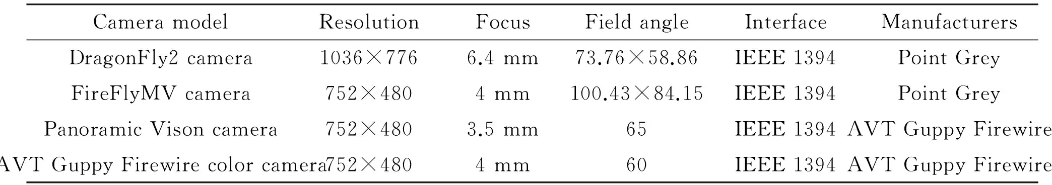
Table 1 Camera parameters.

Fig.1 The binocular vision products.
2.3Panoramicvisiontechnology
Panoramic vision technology is divided into single-camera 360° rotary imaging, multi-camera splicing imaging, fisheye camera imaging and folding reflection panoramic imaging, as shown in Fig.2. Among them, single-camera 360° rotary imaging needs to constantly rotate the camera, requiring a more stable mechanical structure. The system reliability requirements are high; multi-camera splicing imaging requires multiple cameras stitching, the system calibration is more complex, and needs to achieve multi- Synchronization and seamless splicing technology, and has a higher cost.For autonomous platform applications, fisheye camera uses imaging and folding reflective panoramic imaging technology.
新世纪中国工业设计风起云涌,在设计创造的路途中,所有人都未曾停下脚步。作为行业的深潜者与推动者,当回忆如潮而起时,一桩桩、一件件故事在记忆中如飞鱼穿行、腾跃出水,见证着改革开放40年间中国工业设计事业的发展。

Fig.2Fromlefttoright,thefisheyelensimaging,foldingreflectivepanoramicimagingandmulti-cameraimaging,respectively.
3 The Role of Visual Sensor in the Intelligent Driving Environment Perception
To achieve the autonomous driving in an unknown environment, a variety of environments are needed to obtain real-time reliable external and internal information. In developing the domestic and international intelligent driving technology, one of the most useful environmental perception sensors is the visual sensor. From the American DAPAR Challenge to the China Intelligent Vehicle Future Challenge, in the practical research and application development, visual perception is mainly used in the lane departure warning system, the traffic sign security assistance system, the pedestrian detection safety system, the monocular vision advanced driving assistance system (ADAS), and binocular vision sensing system. Among them, the monocular vision advanced driving assistance system Mobileye’s key technology is based on an EyeQTMand EyeQ2TMprocessor using only one camera and bundles of multiple applications together. The functionsinclude Lane Departure Warning(LDW), Vehicle detection based on radar-vision fusion, Forward Collision Warning(FCW), Headway Monitoring and Warning(HMW), pedestrian detection, intelligent headlight control (IHC), traffic sign recognition (TSR), Visual adaptive cruise control (ACC), etc., as shown in Fig.3. Its technology has been used in BMW, GM, Volvo, Hyundai, Renault and other vehicles.
Google’s autonomous vehicle uses the Point Grey Grasshopper 5 megapixel color camera to measure the traffic light status, by selecting the 2040×1080 region of the pixel area of interest to operate, thehorizontal viewing angle of 30 degrees. The farthest detection distance is 150 meters, as shown in Fig.4. And the precision positioning technology is applied to assist the detection. The position and height information of each traffic light is marked on the pre-acquired map. The autonomousdriving relies on its own precise positioning information to calculate the relative position relationship between the current traffic light and the camera. According to the projection relationship of the image, it will limit the location of each traffic light in the image, thus greatly reduces the interference and improves the efficiency of the algorithm, the preparation rate meets 0.99, as shown in Fig.5.
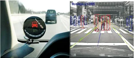
Fig.3TheADASsystemandpedestriandetectiondiagram.

Fig.4Googleautonomouscarcameralayout.

Fig.5Googleshowsthetrafficlightlimitprocessingarea.
Braive Smart Car from The University of Parma, Italy, is equipped with 10 cameras for lane lines, traffic signs, and obstacle detection. They installed four cameras at the rearview mirror, formed a long and short binocular vision system, while a single camera also had the function of detecting the road and traffic signs. Exterior mirrors and cameras on both sides of the front are used for lane or crossroads waiting for vehicle detection. The rear of the vehicle is fitted with a set of stereoscopic vision systems consisting of two cameras to detect rear proximity obstacles as shown in Fig.6.

Fig.6“Braive”cameralayoutandfieldofview.
Porter smart car from The University of Parma, Italy, has a set of two cameras composed of binocular stereoscopic vision system at the front and the rear of the car, the car behind the mirror with three 65 horizontal field angle camera, composed of the 180 degrees panoramic image in front of the vehicle, which makes it possible to do the vehicle detection and tracking in any direction, as shown in Fig.7.
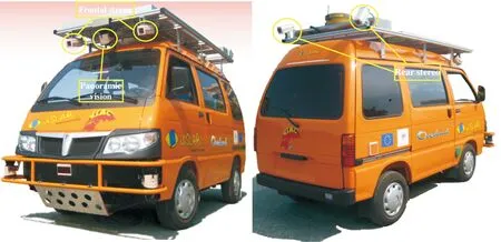
Fig.7Porterintelligentcarcameralayout.
Oxford University Bowler Wildcat intelligent car used Point Grey Bumblebee2 stereo camera Stereo vision system, pre-collected road images to generate maps, and compared with the historical image, positioning the current vehicle location and navigation, while detecting the obstacles. Horizontal field of view is 65 degrees, the image resolution is 512×384, as shown in Fig.8.

Fig.8BowlerWildcatintelligentcarcameralayout.
Carnegie Mellon University BOSS intelligent Car uses two Point Grey Firefly color cameras for road detection, assesses road trends, and detects static obstacles on the road, as shown in Fig.9.

Fig.9CMUBOSSintelligentcarcameralayout.
Binocular vision technology is rarely used in intelligent vehicle obstacle detection, mainly stays in the theoretical research and experimental verification stage. In 2004 and 2005, the GOLD (Generic Obstacle and Lane Detection) system of the Parma University in Italy, using the V parallax algorithm, relying on three cameras to form two binocular vision systems with variable baseline lengths to achieve obstacle detection in unstructured roads. University of Oxford Bowler Wildcat intelligent vehicle Point Gray Bumblebee2 stereo camera Stereo vision system, used the reflection of panoramic imaging algorithm to achieve visual SLAM.
3.1 Lane information extraction technology
The lane information extraction is mainly done to determine the lateral position of the vehicle in the lane, the direction of the vehicle relative to the lane centerline, the lane geometry, such as the lane width, curvature, and so on. The extraction of lane information generally includes two steps: lane detection and tracking. In the absence of prior knowledge limits, lane detection determines the lane boundary in a single image. The lane tracking determines the position of the lane in the sequence image, and the current frame lane position can be limited by the information about the lane boundary position in the previous frame image. The main algorithms are Kalman filter, extended Kalman filter and particle filter.
3.2 Obstacle detection technology
Obstacle detection is an important guarantee for the safe driving of intelligent vehicles. Obstacles appear unpredictable, can not be based on pre-set electronic map to avoid obstacles, only in accordance with the vehicle in advance of the process of discovery, immediately deal with. Obstacle detection based on monocular vision technology is mainly used to detect vehicles and pedestrians. The main algorithms are feature-based obstacle detection technology and obstacle detection technology based on theoptical flow field.
3.3 Identification of traffic signs
The identification technology of traffic signs mainly includes two basic technical aspects. Firstly, the traffic signs are detected, including the traffic signs location and pretreatment. Secondly, the traffic signs are identified, including the feature extraction and classification of traffic signs. The main algorithm of traffic sign recognition is the traffic mark detection and template matching method based on the color image. The traffic sign discriminant algorithm is mainly the traffic sign difference method.
3.4 Visual SLAM technology
Simultaneous Localization And Mapping (SLAM) has high accuracy in direction measurement, low computational load, flexible and inexpensive, but deep recovery of information. The feature map is the main environmental representation based on the visual SLAM method. Its characteristic is mainly the corner feature. Harris, KLT and SIFT feature are the point feature detection methods commonly used in visual SLAM. Monocular vision SLAM is mostly based on the extended Kalman filter method. Oxford University has achieved the positioning and navigation by using visual SLAM method and applied it to real-time road test.
4 Vision Sensor Architecture and Environmental Awareness and Processing
Intelligent vehicle environment awareness technology includes road information, traffic signs information, pedestrian behavior information, and peripheral vehicle information. Information through a variety of vehicle heterogeneous sensor equipment to obtain, there are a variety of cameras, radar (such as laser radar, millimeter-wave radar, ultrasonic radar, infrared radar, etc.), GPS receiver, inertial navigation and so on. When a human driver performs a complex driving operation, such as lane changing, it will focus on different areas to ensure lane safety. Radar sensor has many different types, multi-heterogeneous radar sensor can get real-time information through effective extraction, and learn from the characteristics of human cognition. The sensor model, quantity and installation location of different intelligent driving test platform are different, and the sensor information processing module is different, as shown in Fig.10.The information provided by different driving maps has no fixed standard of its granularity. The number and interface of the autonomous system software modules are different. To drive the brain as the core, form the driving perception, and use the driving cognitive formal language, you can design a common autonomous software architecture. In this architecture, the intelligent decision module is not directly coupled with the sensor information. Through the sensor information and map of a priori information, we can form a comprehensive driving situation to complete intelligent decision-making, and use the image segmentation algorithm to extract the target area, and then focus on regional segmentation. According to the input characteristic calculation result, the driver searches for the obstacle in the secondary division area, outputs the travelable road area, and performs the information sensing method.

Fig.10Intelligentcarhardwarearchitectureplatform.
Human drivers integrated the coordination of sensory memory, working memory, long-term memory, computing center and learning different areas of the brain, complete driving activities. The driving function of the intelligent driving system simulates human-related functions and also requires a series of the above-mentioned key functions and allows these functions to work together, as shown in Fig.11. These key features include sensor information acquisition and processing, driving map calibration and mapping, driving cognitive formal language and intelligent decision making[19].
Among them, the sensor information acquisition, including camera, laser radar, and millimeter-wave radar, combined positioning system and other information, in which the visual sensor to complete the lane marking identification, traffic signal recognition, traffic signs identification. In the field of image processing, it will involve the object classification and recognition, using SIFT, HOG and other image feature methods to identify, and using SVM and other machine learning algorithm to complete the classification and identification of objects[20-22]. For intelligent driving test, the application of driving map prior knowledge can improve object recognition performance. Google smart car records the traffic lights, traffic signs and other static traffic elements of the precise location in advance, during the identification of objects, uses the precise location of vehicles, the collection of traffic lights, traffic signs location information mapped to the image, to quickly determine the region of interest, which greatly improves the speed and accuracy of recognition[23]. In addition, simultaneous positioning and mapping (SLAM) can be accomplished using image information, which helps the vehicle acquire its own precise location[24]. As the visual sensor imaging by the perceived object’s light or reflection is affected by external lighting conditions greatly, limiting the scale of application of visual sensors.

Fig.11 Driving brain and human brain function technical structure.
According to the road segmentation algorithm based on inverse perspective transformation, the working area of the camera is shown in Fig.12, which can be used to analyze the effective working area of the visual sensor and the radar sensor. Fig.12 shows the working area of the two sensors. The intersection area is the common area of the camera and the radar sensor.

Fig.12 Schematic diagram of the sensor operating area.
Unearthed road surface unevenness will cause the body bumps, so the maximum speed of the intelligent vehicle is set at 20 km/h (5.6 m/s), the maximum deceleration of the intelligent driving vehicle is 6 m/s2. From the detection of the road, it can not travel to stop, we need at least 5 m distance. Braking is a gradual increase, taking into account the time-consuming of the algorithm and time-consuming response of the braking system, the safety distance is set to 10 m, the algorithm only concerned about the vehicle in front of 10 m within the road area. From the perspective of human cognition, the target area within 10 m of the intelligent driving vehicle is first visually judged. Then, whether there is an obstacle in the target area or not, if not it is considered to be a feasible area, on the contrary, it is considered that the target area in front of the obstacle is a travelable area. Based on the cognitive model algorithm, with reference to the principle of human cognition, we only need to consider the areas that may bring potential threats to the self driving of autonomous vehicles, and do not need to consider the farther areas, which save the computing resources for the algorithm to meet the real time principle. Finally, the algorithm should take into account the robustness criterion, so that the decision result of the input decision layer is expected to have better anti-interference as much as possible. In summary, the process of visual sensor information sensing and processing algorithm is shown in Fig.13.
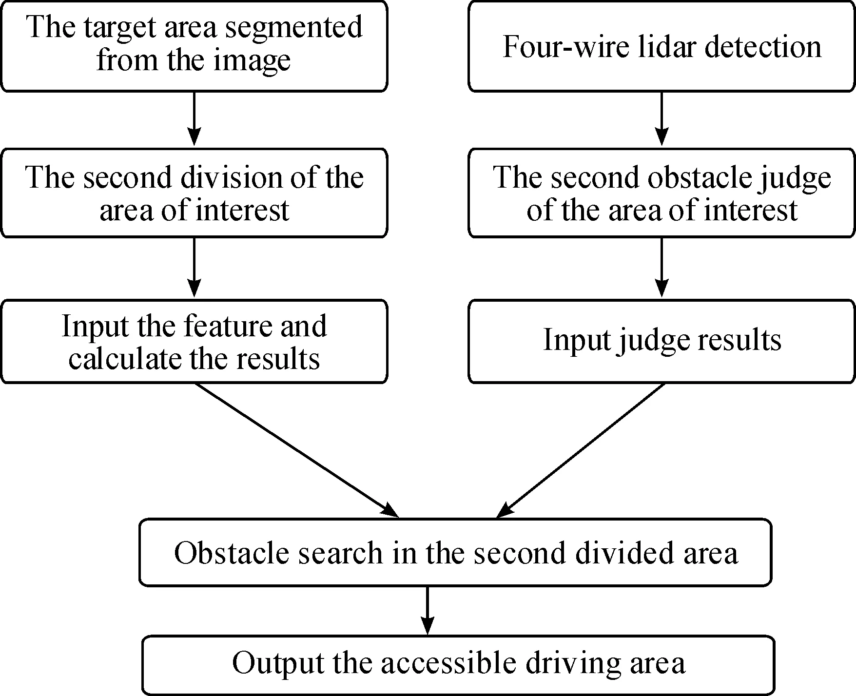
Fig.13Graphicsensorinformationfusionalgorithmflowchart.
4.1Targetareaandobstacleinformationextraction
Smart cars, when driving (especially autonomous exchange lane) in the process of real-time detection of peripheral vehicles, pedestrians and other obstacles, need to determine the travel area to ensure the safety. Obstacle detection is the key and difficult point of environmental perception technology. As the active sensor, it has the characteristics of good direction, high precision, and reliable data. The aim of this paper is to use the radar for road identification and the second decision of the obstacle in the area of interest, to obtain a safe path of the road which can be confirmed. Firstly, a target area is determined by the visual sensor. The target area is calculated by the image data obtained by the visual sensor. Then, the target area is searched and the safe and feasible road area is obtained.
4.2Thetargetareaofsecondaryprocessing
The original image obtained by the visual sensor is transformed into the road plane, and the initial target road area is obtained by the image segmentation method. In order to meet the real-time criteria, the algorithm focuses on the road area within 10 m of the intelligent vehicle. And to ensure the robustness, the judgment result is simple and practical. Therefore, the initial target road area needs to be further extracted and processed, and the Fig.14 shows the extraction process.

Fig.14Theinitialroadareaofthemapisfurtherextractedfromtheprocessdiagram.
The red areas in Fig.14 (b) and (c) show the road area obtained by the image segmentation algorithm. According to the camera to calibrate the internal and external parameters, you can calculate the corresponding relationship between the pixel and the actual distance, so you can get the extracted target area length, area, average width and other information. This paper intercept 10 m within the area of concern for processing. At the same time as the smart car does not necessarily travel in the middle of the road, so the road area is divided into two parts according to the middle of the car’s head, as shown in Fig.15, respectively, calculate its area, according to the relationship between the size of the pixel and the actual distance, and get the average road width of the left and right sides.
Let the last calculated road width average of the left and right sides belandr, then the final target area is a rectangular area as is shown in Fig.16.

Fig.15 The area of attention.
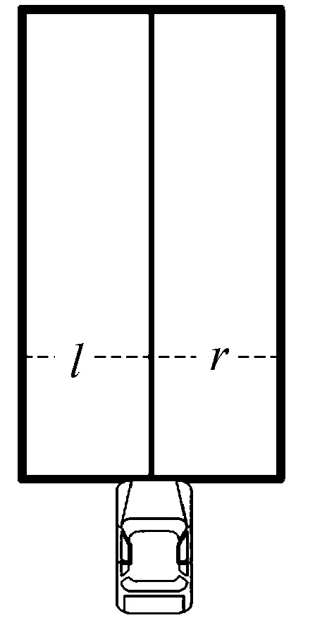
Fig.16 The target area after secondary processing.
4.3 The second judge of the obstacle
The obstacle detection algorithm based on LIDAR can output the obstacle ID and obstacle number of all clustering results in the radar field of view, and can also obtain the coordinates information of the obstacle center point. Similarly, only concerned about the radar output within 10 m range of obstacle clustering results, for the further range of the obstacle detection results, it only acts as a basis for tracking comparison. Fig.17 is the result of the direct output of the obstacle detection algorithm. Fig.18 shows the output of the obstacle within 10 m after the second decision. The red sector shows the 10 m field of view of the radar. The obstacle in the 10 m field of view is signed by a red line.
4.4 Accessible road area output
Finally, the sensors need search obstacle for the target area. If there is no obstacle in the target area, it is considered that the target area is a road area that can be traveled; otherwise, the target area before the obstacle is considered to be a feasible road area. The specific output process of the road area is as follows:
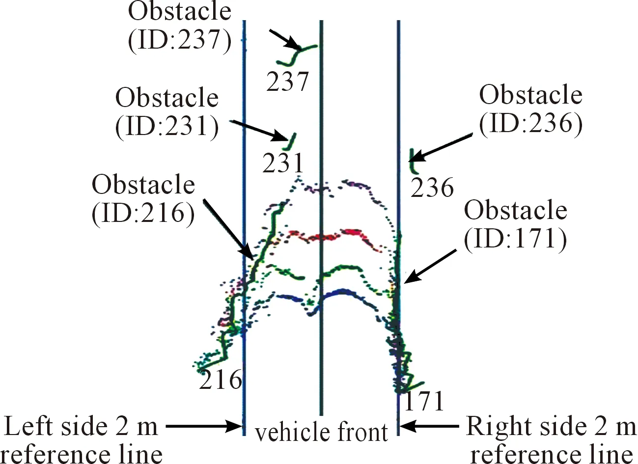
Fig.17 Initial barrier detection results.
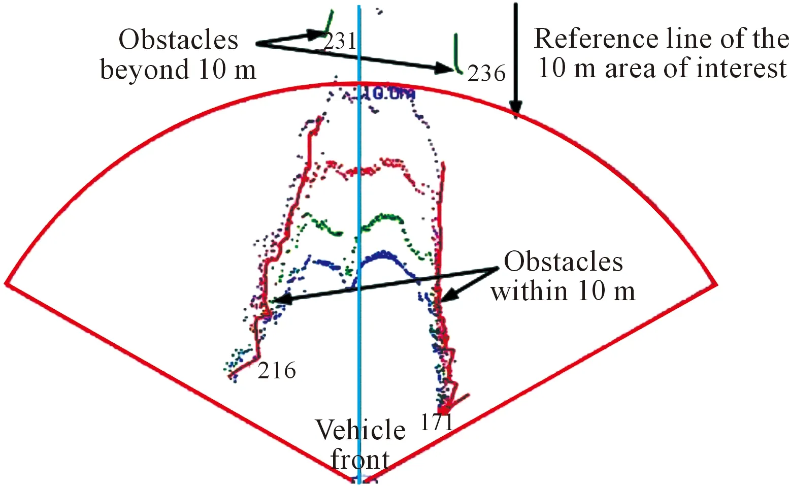
Fig.18 Obstacle detection after secondary judgment.
First of all, set the camera output of the road width on both sides arel,r. In theOxycoordinate system of the vehicle plane, four straight lines ofx=-l,x=r,y=0 andy=10 are drawn so as to intersect with the previous two straight lines to obtain a closed rectangular space. The rectangular space is the target area.
Secondly, search for obstacle object, if there is an obstacle object in the target area, extract the value of all the obstacles in this area. By comparing, get the minimum valueymin, draw liney=ymin, discard the liney=10, get a new rectangular area. The new rectangular area is the accessible road area. The feasible road area obtained by the algorithm is shown in Fig.19. Since the left and right sides of the road area obtained from the visual information do not contain an obstacle, it is considered that the length of the accessible road area is 10 meters oryminmeters, and the width of the left and right sides is (l+r) meters, which mees the intelligent vehicle accessible area output.

Fig.19 Map travel road area diagram.
5 Conclusion
As the machine vision system can quickly obtain a lot of information, easy to integrate design information and processing control information, therefore, in the modern automated production process, people widely use it in machine vision system monitoring, product testing and quality control and other fields. In the intelligent driving vehicle, since the sensor is cheaper than LIDAR and can obtain rich information, thesensoris the intelligent driving vehicle technology research focus, which has broad application prospects. It is expected that with the maturity and development of machine vision technology, the intelligence of the algorithm will be improved, it will be more and more widely used in intelligent driving vehicles. The future intelligent driving vehicles will mainly rely on machine vision to conquer the environment perception task.
Acknowledgment
This work was supported by National Natural Science Foundation of China under Grant No.61035004, No.61273213, No.61300006, No.61305055, No.90920305, No.61203366, No.91420202, No.61571045, No.61372148, the National High Technology Research and Development Program (“863” Program) of China under Grant No.2015AA015401, and the National High Technology Research and Development Program (“973” Program) of China under Grant No. 2016YFB0100903, and the Junior Fellowships for Advanced Innovation Think-tank Program of China Association for Science and Technology under Grant No.DXB-ZKQN-2017-035, and the Beijing Municipal Science and Technology Commission special major under Grant No. D171100005017002.
[1]D.W.Gage, UGV History 101: A brief history of unmanned ground vehicle (UGV) development efforts,UnmannedSystems, vol.13, pp.9-32, 1970.
[2]T.Kanade and C.Thorpe,CMUstrategiccomputingvisionprojectreport: 1984to1985.Carnegie-Mellon University, The Robotics Institute, pp.10-90, 1986.
[3]M.Williams, PROMETHEUS-The European research programme for optimising the road transport system in Europe, inProceedingsofIEEEColloquiumonDriverInformation, 1988, pp.1-9.
[4]S.Tsugawa, M.Aoki, A.Hosaka, and K.Seki, A survey of present IVHS activities in Japan,ControlEngineeringPractice, vol.5, no.11, pp.1591-1597, 1997.
[5]M.Yang, Overview and prospects of the study on driverless vehicles,JournalofHarbinInstituteofTechnology, vol.38, no.8, pp.1259-1262, 2006.
[6]H.B.Gao, X.Y.Zhang, T.L.Zhang, Y.C.Liu, and D.Y.Li, Research of intelligent vehicle variable granularity evaluation based on cloud model,ActaElectronicaSinica, vol.44, no.2, pp.365-374, 2016.
[7]Y.R.Zhang, C.J.Guo, and R.Z.Niu, Research on stereo-vision aided GNSS localization for intelligent vehicles,ComputerEngineeringandApplications, vol.52, no.17, pp.192-197, 2016.
[8]J.Ziegler, H.Lategahn, M.Schreiber, C.Keller, C.Knoppel, J.Hipp, M.Haueis, and C.Stiller, Video based localization for bertha, inProceedingsof2014IEEEInternationalConferenceonIntelligentVehiclesSymposium, 2014, pp.1231-1238.
[9]R.W.Wolcott and R.M.Eustice, Visual localization within LiDAR maps for automated urban driving,inProceedingsof2014IEEEInternationalConferenceonIntelligentRobotsandSystems, 2014, pp.176-183.
[10] H.X.Duan,Outdoorvisionlocalizationandmapbuildingfortheunmannedvehiclebasedonbinocularvision.Dalian University of Technology, 2015.
[11] Q.L.Fang,Researchontrafficmarkrecognitionmethodbasedonunmannedvehicleassistednavigation.Anhui University, 2012.
[12] F.Bernuy, D.Solar, I.Parra, and P Vallejos, Adaptive and real-time unpaved road segmentation using color histograms and RANSAC, inProceedingsofthe9thIEEEInternationalConferenceonControlandAutomation, 2011, pp.136-141.
[13] Z.X.Chen,Detectionandidentificationofroadtrafficsignsinurbanareas.University of Science & Technology China, 2012.
[14] J.C.Hu,Researchontrafficsigndetectionandrecognitionbasedonstablefeature.Hunan University, 2012.
[15] D.Smorawa and M.Kubanek, Analysis of advanced techniques of image processing based on automatic detection system and road sings recognition,JournalofAppliedMathematicsandComputationalMechanics, no.1, pp.13, 2014.
[16] N.Kaempchen, B.Schiele, and K.Dietmayer, Situation Assessment of an Autonomous Emergency Brake for Arbitrary Vehicle-to-Vehicle Collision Scenarios, inProceedingsofIEEETransactionsonIntelligentTransportationSystems, 2009, no.10, pp.678-687.
[17] Y.Li,Researchofobstaclerecognitionbasedonbinocularvision.Wuhan University of Technology, 2007.
[18] Z.G.Zhu, X.Y.Lin, and D.J.Shi, A real-time visual obstacle detection system based on reprojection transformation,Journalofcomputerresearchanddevelopment, no.1, pp.77-84, 1999.
[19] D.G.Lowe, Object recognition from local scale-invariant features, inProceedingsoftheseventhIEEEinternationalConferenceonComputerVision, 1999, no.2, pp.1150-1157.
[20] D.G.Lowe, Distinctive image features from scale-invariant keypoints,Internationaljournalofcomputervision, vol.60, no.2, pp.91-110, 2004.
[21] N.Dalal and B.Triggs, Histograms of oriented gradients for human detection, inProceedingsofIEEEComputerSocietyConferenceonComputerVisionandPatternRecognition, 2005, no.1, pp.886-893.
[22] X.Y.Zhang, H.B.Gao, M.Guo, G.P.Li, Y.C.Liu, and D.Y.Li, A study on key technologies of unmanned driving,CAAITransactionsonIntelligenceTechnology, vol.1, no.1, pp.4-43, 2016.
[23] J.Levinson, J.Askeland, J.Dolson, and S.Thrun, Traffic light mapping, localization, and state detection for autonomous vehicles, inProceedingsof2011IEEEInternationalConferenceonRoboticsandAutomation(ICRA), 2011, pp.5784-5791.
[24] N.Engelhard, F.Endres, J.Hess, J.Sturm, and W.Burgard, Real-time 3D visual SLAM with a hand-held RGB-D camera, inProceedingsoftheRGB-DWorkshopon3DPerceptioninRoboticsattheEuropeanRoboticsForum, 2011, pp.180.
•Xinyu Zhang and Buyun Gao are with Information Technology Center, Tsinghua University, Beijing 100083, China.
•Hongbo Gao and Guotao Xie are with State Key Laboratory of Automotive Safety and Energy, Tsinghua University, Beijing 100083, China. Email: ghb48@mail.tsinghua.edu.cn.
•Buyun Gao is with School of Software, Beijing Institute of Technology, Beijing 100081, China.
•Deyi Li is with Institute of Electronic Engineering of China, Beijing 100039, China.
*To whom correspondence should be addressed. Manuscript
2017-08-06; accepted: 2017-9-18
猜你喜欢
陕西档案(2020年1期)2020-04-14
小学生学习指导(低年级)(2019年12期)2019-12-04
小学生学习指导(低年级)(2019年12期)2019-12-04
传媒评论(2019年12期)2019-08-24
今日农业(2019年13期)2019-01-03
家庭影院技术(2017年11期)2017-12-20
中国卫生(2016年6期)2016-11-23
中国卫生(2016年1期)2016-11-12
中共党史研究(2013年10期)2013-04-27
小学生·多元智能大王(2006年5期)2006-05-10
 CAAI Transactions on Intelligence Technology2017年3期
- CAAI Transactions on Intelligence Technology的其它文章
- Micro Structure of Injection Molding Machine Mold Clamping Mechanism: Design and Motion Simulation
- Retinal Image Segmentation Using Double-Scale Nonlinear Thresholding on Vessel Support Regions
- The Fuzzification of Attribute Information Granules and Its Formal Reasoning Model
- Enriching Basic Features via Multilayer Bag-of-words Binding for Chinese Question Classification
- Technology of Intelligent Driving Radar Perception Based on Driving Brain
- Interactions Between Agents:the Key of Multi Task Reinforcement Learning Improvement for Dynamic Environments