
Numerical Predictions of the PPTC Propeller Tip Vortex Cavitation in Uniform Flow
2018-01-04 08:24LIUDengchengWEIXizhong
船舶力学 2017年12期
LIU Deng-cheng,WEI Xi-zhong
(1.National Key Laboratory on Ship Vibration&Noise,China Ship Scientific Research Center,Wuxi 214082,China;2.Jiangsu Key Laboratory of Green Ship Technology,Wuxi 214082,China)
Numerical Predictions of the PPTC Propeller Tip Vortex Cavitation in Uniform Flow
LIU Deng-cheng1,2,WEI Xi-zhong1
(1.National Key Laboratory on Ship Vibration&Noise,China Ship Scientific Research Center,Wuxi 214082,China;2.Jiangsu Key Laboratory of Green Ship Technology,Wuxi 214082,China)
Using Sauer’s cavitation model,the effects of grid type and turbulence model on propeller tip vortex cavitation simulation results are researched.It shows that the Sauer’s cavitation model is suitable for the propeller tip vortex cavitation simulation,and the key point is the grid density at the tip vortex cavitation region.A local grid refinement method is proposed.The simulation of PPTC propeller wetted flow and tip vortex cavitation flow is implemented,and the propeller tip vortex cavitation shape is compared with the corresponding experiments results.In order to analyse the main features of tip vortex and tip vortex cavitation, ‘Q-Criterion’ and ‘λ2-Criterion’ are used.The vorticity distribution in the tip vortex region of wetted flow presents single hump shape,and the minimum value is at the tip vortex core.The vorticity distribution in the tip vortex cavity region of cavitation flow presents double humps shape,and the minimum value is not at the tip vortex cavitation core.
uniform flow;tip vortex cavitation;propeller;numerical prediction
0 Introduction
Cavitating flows are highly complicated because it is a rapid phase change phenomenon,which often occurs in the high-speed or rotating fluid machineries when the local pressure drops below its vapor pressure.It is well known that the cavitating flow raises up the vibration,the noise and the erosion.Therefore,the research on the cavitating flow is of great interest.
Cavitation presents complex unsteady,turbulent and multi-phase flow phenomena with a large density difference and mass transfer.These features result in a unique challenge for the simulation of cavitating flows,especially tip vortex cavitation.
Numerical method is a highly important approach for studying the cavitating flow.Computational methods for cavitation have been studied since over two decades ago.In general,the methods can be largely categorized into two groups:single-phase modeling with cavitation interface tracking and multi-phase modeling with cavitation interface capturing.
The former approach has been widely adopted for inviscid flow solution methods,such as potential flow boundary element methods.Kinnas and Fine[1]developed non-linear boundaryelement method based on speed potential,and so on.
The latter approach can be adopted for viscous flow solution methods,and is very popular in the cavitation research recently with the development of CFD.The cavitating flow is treated as the homogeneous equilibrium single-fluid flow which satisfies Navier-Stokes equation.In this approach,the mixture density concept is introduced.The key challenge is how to define the mixed density of the single-fluid flow.In general,the cavitation modeling can be largely categorized into two groups according to the relation that defines the variable density field.One cavitation modeling proposed by Delannoy and Kueny[2]is based on the equation of state that relates pressure and density.By assuming the cavitating process to be isothermal,mixed density is simply a function of local pressure.The other cavitation modeling is based on mass transport equation which introduces the concept of volume fraction,and the source term of the mass transport equation controlled the evaporation and condensation transfer process,and then the mixed density is calculated using the volume fraction.Kubota et al[3]coupled the Rayleigh-Plesset equation to compute the volume fraction based on the bubble radius.A mass transport equation cavitation model has been recently developed.Merkle et al[4],Kunz et al[5-6],Senocak and Shhy[7-9],Singal et al[10],Zwart et al[11],Schnerr and Sauer[12-14]and Liu[15]have employed similar idea based on this concept with differences in the source terms.
Many people did some research about the simulation of foil and propeller cavitation,and these work main focus on sheet cavitation and cloud cavitation.For example,Niklas et al[16]simulated two and three dimensional cavitating flow around hydrofoil with Kunz’s cavitation model.Shin Hyung Rhee and Kawamura[17]studied the cavitating flow around a marine propeller using an unstructured mesh with FLUENT 6.1.Liu[18-20]simulated the cavitating performance of marine propeller using a hybrid mesh based on RANS solver for singhal model.Coutier-Delgosha et al[21]computed cavitating flows around 2D foil by modifying turbulence model,and the sheet cavity length and the dynamic shedding behaviour were very similar to those observed in the experiment.Li[22-23]and Liu[24]predicted unsteady cavitating flows of 2D NACA0015 foil and 3D twisted foil using the same idea.
In this paper,the effects of grid type and turbulence model on propeller tip vortex cavitation simulation results are researched.A local grid refinement method is proposed.The simulation of PPTC propeller wetted flow and tip vortex cavitation flow is implemented.In order to analyse the main features of tip vortex and tip vortex cavitation, ‘Q-Criterion’ and ‘λ2-Criterion’are used.
1 Research object
There are two international standard propeller models,one was named E779A which was designed in 1959 by INSEAN tank of Italy,the other was named PPTC which was proposed on the first workshop on cavitation and propeller performance.
The first workshop on cavitation and propeller performance was held in Hamburg,Ger-many,at the end of smp’11.The workshop emphasis will be on prediction of PPTC propeller hydrodynamic performance and propeller cavitation performance in uniform flow,the test was blind test at Potsdam Model Basin.A large number of different research groups participated,and the workshop become a success.
And the second international workshop on cavitating propeller performance was held in Austin,USA,at the end of smp’15.The workshop emphasis will be on prediction of PPTC propeller hydrodynamic performance and propeller cavitation performance in oblique flow,and the blind test will also be performed at Potsdam Model Basin.
PPTC is a five bladed propeller(see Fig.1).It is a controllable pitch propeller with diameter D=0.250 m,hub diameter ratio of 0.3,pitch-to-diameter ratio of 1.635 at 0.7 radial section,skewed angle of 19.12°and area ratio of 0.78.
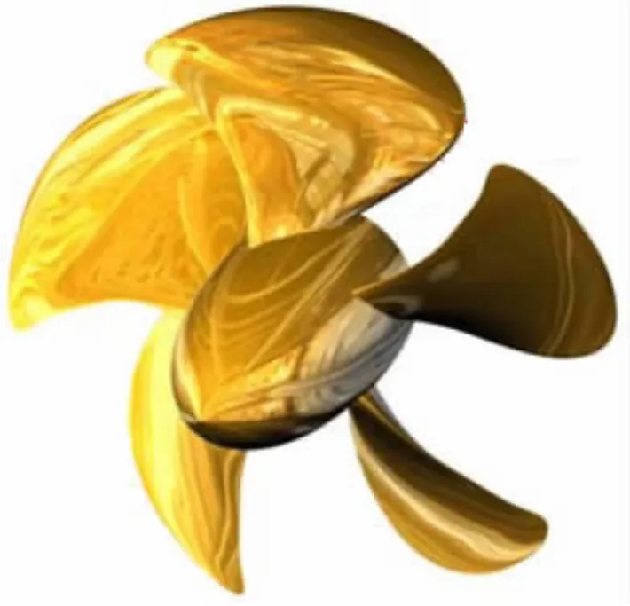
Fig.1 The geometry of PPTC
2 Numerical methods
2.1 Governing equations
For the multi-phase flow solutions,the single-fluid mixture model is employed.The governing equations are written for the mass and momentum conservation of mixed fluid as follows:

where ρmis the mixed density,μ is the mixed viscosity,μtis the mixed eddy viscosity.
2.2 Sauer’s cavitation model
The mixed density is controlled by vapor mass fraction f:

The vapor transport equation is written as:

where ρvand ρlare the density of vapor and liquid,respectively.are the rates of vapor generation and condensation,respectively.Sauer derived the expressions ofwhere pvis saturated vapor pressure.


2.3 Grid type and turbulence model
For this simulation,the computational domain was created as block which is divided into static region and rotating region around propeller.Boundary conditions were set as follows:on the inlet boundary and the outer boundary,velocity components of uniform stream with the given inflow speeds were imposed;on propeller surface,the no slip condition was imposed;on the exit boundary,the static pressure was set to a constant value,which is determined by cavitation index in the cavtating cases.The initial and the free-stream turbulence quantities are set to 1%turbulence intensity and a turbulence viscosity ratio equal to 10.The advance coefficient is 1.019 and the cavitation number is 2.024.The case of computation is presented in Tab.1.The expression of advance ratio,cavitation number,thrust and torque coefficients is written as follows:

For research the effect of different grid type and turbulence model,four different grid types filled the rotating region and three different turbulence models are employed.The grid types include trim mesh,trim mesh with tip region refinement,tetrahedral mesh and polyhe-dral mesh;these are named as Trim,Trim-tip,Tet and Poly,respectively.The turbulence models include k-ε,SST k-ω and Reynolds stress turbulence model(RSM).In Tab.2,the cases of cavitation computation about grid type and turbulence model are presented.The corresponding grid types are showed in Fig.2.For tip vortex region grid refinement,a block was created according to the helix line,and the pitch is equal to the propeller pitch at the 1.0 time radius(see Fig.3).

Tab.1 The case2-1 of cavitation computational
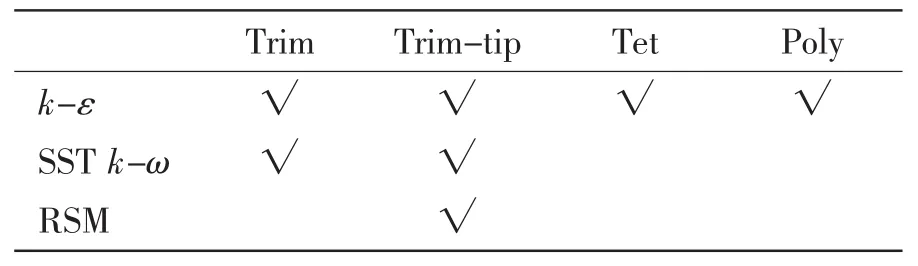
Tab.2 The cases of computation aboutgrid type and turbulence model

Fig.2 The four different grid types

Fig.3 The block for tip vortex region grid refinement
3 Results and discussion
3.1 The effect of grid types and turbulence model
We simulated propeller cavitation performance at one advance ratio and one cavitation index with different grid types and different turbulence models.It has seven cases in Tab.2.


Fig.4 The computational cavity shapes and compared with experimental result
The comparison of the computed cavity shapes of different cases with the experimental result which come from Potsdam Model Basin at the first workshop on cavitation and propeller performance are presented in Fig.4.The computed cavity shapes can be confirmed by the isosurface of vapor volume fraction of 0.1.From the experimental result,we clearly see that the cavitation is to occur in the tip,root and leading edge of suction side of propeller.In Fig.4,it shows that the all computational cases catch the cavity in the root and leading edge;only the computational cases of tip vortex region grid refinement catch the tip vortex cavitation.The computational results indicated that the tip vortex cavity missing in some computations is attributed mainly to the mesh resolution in the cavitating region,but most grid types and turbulence model can deal well with cavitation flow,the Sauer’s cavitation model is not only suitable for the sheet cavitation simulation but also suitable for the propeller tip vortex cavitation simulation,where the key point is the grid density at the tip vortex cavitation region.
3.2 The features of tip vortex and tip vortex cavitation
According to the simulation results of PPTC propeller wetted flow and tip vortex cavitation flow using tip vortex region grid refinement and the SST k-ω turbulence model,we analyse the main features of tip vortex and tip vortex cavitation.Fig.5 presents comparison between tip vortex and tip vortex cavity.The iso-surface of the λ2 equal to 5 000 represents the tip vortex in wetted flow and tip vortex cavity in cavitation flow.We can clearly see that the streamlines of tip vortex are more helical than the streamlines of tip vortex cavity.


Fig.6 The vorticity comparison between tip vortex and tip vortex cavity(x=0.32R)
The vorticity comparison between tip vortex and tip vortex cavity at the cross face of propeller downstream(x=0.32R)is presented in Fig.6.The vorticity and λ2 distribution across the tip vortex respectively(r=0.96R,x=0.32R)are presented in Fig.7 and Fig.8.The vorticity distribution in the tip vortex region of wetted flow presents single hump shape,and the minimum value is at the tip vortex core.The vorticity distribution in the tip vortex cavity region of cavitation flow presents double humps shape,and the minimum value is not at the tip vortex cavitation core.It is showed that the vorticity and the absolute value of λ2 in the tip vortex of wetted flow are larger than these in the tip vortex cavity of cavitation flow,and the radius of tip vortex cavity in cavitation flow is larger than the radius of tip vortex in wetted flow.The reason is that the pressure in the tip vortex of wetted flow is lower than the pressure in the tip vortex cavity of cavitation flow which is about equal to the saturated pressure.

Fig.7 The vorticity distribution across the tip vortex(r=0.96R,x=0.32R)

Fig.8 The λ2 distribution across the tip vortex(r=0.96R,x=0.32R)
4 Conclusions
Using Sauer’s cavitation model,the effects of grid type and turbulence model on propeller tip vortex cavitation simulation results are researched.It shows that the Sauer’s cavitation model is suitable for the propeller tip vortex cavitation simulation,and the key point is the grid density at the tip vortex cavitation region.A local grid refinement method is proposed.The simulation of PPTC propeller wetted flow and tip vortex cavitation flow is implemented,and the propeller tip vortex cavitation shape is compared with the corresponding experimental results.In order to analyse the main features of tip vortex and tip vortex cavitation,‘Q-Criterion’ and‘λ2-Criterion’ are used.The vorticity distribution in the tip vortex region of wetted flow presents single hump shape,and the minimum value is at the tip vortex core.The vorticity distribution in the tip vortex cavity region of cavitation flow presents double humps shape,and the minimum value is not at the tip vortex cavitation core.
[1]Kinnas S A,Fine E A.Numerical nonlinear analysis of the flow around 3-D cavitating hydrofoil[J].Journal of Fluid Mechanics,1993,254:151-181.
[2]Delannoy Y,Kueny J L.Two phase flow approach in unsteady cavitation modeling[C]//ASME Fluids Engineering Division.Toronto,Ontario,1990:153-158.
[3]Kubota A,Kato H,Yamaguchi H.A new modeling of cavitating flows:A numerical study of unsteady cavitation on a hydrofoil section[J].J of Fluid Mechanics,1992,240:59-96.
[4]Merkle C L,Feng J,Buelow P E O.Computational modeling of the dynamics of sheet cavitation[C]//Proceedings of 3rd International Symposium on Cavitation.Grenoble,France,1998.
[5]Kunz R F,Boger D A.A preconditioned Navier-Stokes method for two-phase flows with application to cavitation prediction[J].Computers&Fluids,2000,29:849-875.
[6]Kunz R F,Lindau J W.Unsteady RANS and detached eddy simulations of cavitating flow over a hydrofoil[C]//Fifth International Symposium on Cavitation,cav2003.Osaka,Japan,2003:1-4.
[7]Senocak I,Shyy W.Numerical simulation of turbulent with sheet cavitation[C].Fourth International Symposium on Cavitation,cav2001,SessionA7.002,2001.
[8]Senocak I,Shyy W.A pressure-based method for turbulent cavitating flow computation[J].Journal of Computational Physics,2002,176:363-383.
[9]Senocak I,Shyy W.Interfacial dynamics-based modelling of turbulent cavitating flows,Part-1:Model development and steady-state computations[J].Int.J Numer.Methods Fluids,2004,44(9):975-995.
[10]Singhal A K,Athavale M M.Mathematical basis and validation of the full cavitation model[J].Journal of Fluids Engineering,2002,124:617-624.
[11]Zwart P J,Gerber A G,Belamri T.A two-phase flow model for predicting cavitation dynamics[C]//Proceedings of International Conference on Multiphase Flow.Yokohama,Japan,2004.
[12]Schnerr G H,Sauer J.Physical and numerical modeling of unsteady cavitation dynamics[C]//Proceedings of 4th International Conference on Multiphase Flow.New Orleans,USA,2001.
[13]Schnerr G H,Sezal I H,Schmidt S J.Numerical investigation of three-dimensional cloud cavitation with special emphasis on collapse induced shock dynamics[J].Phys.Fluids.,2008,20(4):040703.
[14]ANSYS Corporation.ANSYS Fluent Documentations[K].2010.
[15]Liu Dengcheng.The numerical simulation of propeller sheet cavitation with a new cavitation model[C]//7th International Conference on Fluid Mechanics,ICFM7.Qingdao,China,2015.
[16]Niklas,Goran Bark,Christer Fureby.Large eddy simulation of cavitating submerged objects[C]//The 8th International Conference on Numerical Ship Hydrodynamics.Busan,Korea,2003.
[17]Shin Hyung Rhee,Takarumi Kawamura.A study of propeller cavitation using a RANS CFD method[C]//The 8th International Conference on Numerical Ship Hydrodynamics.Busan,Korea,2003.
[18]Liu Dengcheng,Hong Fangwen,Zhao Feng,et al.The CFD analysis of propeller sheet cavitation[C]//Proceedings of the 8th International Conference on Hydrodynamics.Nantes France,2008.
[19]Liu Dengcheng,Hong Fangwen.The numerical predicted of SMP11 propeller performance with and without cavitation[C]//Second International Symposium on Marine Propulsors,SMP’11.Hamburg,Germany,2011.
[20]Liu Dengcheng.The numerical predicted of VP1304 propeller cavitation performance in oblique flow[C]//Fourth International Symposium on Marine Propulsors,smp’15.Austin,USA,2015.
[21]Olivier Coutier-Delgosha,Fortes-Patella R,Reboud L.Evaluation of the turbulence model influence on the numerical simulations of unsteady cavitation[J].Journal of Fluids Engineering,2003,125(1):38-45.
[22]Li D Q,Grekula.Prediction of dynamic shedding of cloud cavitation on a 3D twisted foil and comparison with experiments[C]//27th Symposium on Naval Hydrodynamics.Seoul,Korea,2008.
[23]Li Daqing,Mikael Grekula,Per Lindell.A modified SST k-ω turbulence model to predict the steady and unsteady sheet cavitation on 2D and 3D hydrofoils[C]//Proceedings of the 7th International Symposium on Cavitation,CAV2009.Ann Arbor,Michigan,USA,2009.
[24]Liu Dengcheng,Hong Fangwen,Lu Fang.The numerical and experimental research on tip vortex flow and unsteady cloud cavitating flow of 3D elliptical hydrofoil[C]//Proceedings of the 9th International Conference on Hydrodynamics.Shanghai,China,2010.
均流中PPTC螺旋桨梢涡空泡数值预报
刘登成1,2, 韦喜忠1
(1.中国船舶科学研究中心 船舶振动噪声重点实验室,江苏 无锡214082;2.江苏省绿色船舶技术重点实验室,江苏 无锡 214082)
文章采用Sauer空化模型,研究了网格类型和湍流模型对均流中螺旋桨梢涡空泡数值模拟的影响,研究表明,现有的空泡模型适合于螺旋桨梢涡空泡的数值模拟,其中梢涡空泡区域网格密度是关键,文中提出了一种合适的梢涡空泡区域网格加密方法。对PPTC螺旋桨全湿流和梢涡空泡进行了数值预报,螺旋桨梢涡空泡形态与试验结果进行了对比,并应用涡判据“Q准则”和“λ2准则”分析了梢涡与梢涡空泡的流动特征。全湿流中梢涡区域的涡量随周向的分布呈现单峰特性,最小涡量在涡心处,而空泡流中梢涡空泡区域的涡量随周向的分布呈现双峰特性,最小涡量不在涡心处。
均流;梢涡空泡;螺旋桨;数值预报
U661.73
A
国家自然科学基金资助项目(11332009)
刘登成(1982-),男,中国船舶科学研究中心高级工程师;
韦喜忠(1982-),男,中国船舶科学研究中心高级工程师。
U661.73 Document code:A
10.3969/j.issn.1007-7294.2017.12.004
date:2017-07-14
Supported by the National Natural Science Foundation of China(Grant No.11332009)
Biography:LIU Deng-cheng(1982-),male,senior engineer,E-mail:edon_001@163.com;WEI Xi-zhong(1982-),male,senior engineer.
1007-7294(2017)12-1480-09
猜你喜欢
上海交通大学学报(2021年8期)2021-09-02
数字海洋与水下攻防(2021年2期)2021-05-08
中国农村水利水电(2021年2期)2021-03-05
航空发动机(2020年3期)2020-07-24
能源研究与信息(2018年1期)2018-05-08
兰台世界(2017年10期)2017-06-01
系统工程与电子技术(2016年2期)2016-04-16
船海工程(2015年4期)2016-01-05
中国舰船研究(2015年3期)2015-02-07
中国舰船研究(2014年1期)2014-05-14

- 船舶力学的其它文章
- Low-Cycle Fatigue Crack-Propagation Behavior for Ship Cracked Plate Considering Accumulative Plastic Damage
- Numerical Simulation of Deterministic Freak Wave Based on Energy Distribution
- Method of Estimating the Effect of Marine Fouling on Frictional Resistance of Ships
- Evaluation of Viscous Effect on Wave Excitation Force of a Vessel with Transom Stern
- Enhanced Extinction Curve Method for Roll Damping Estimation
- Algorithm Simulation of Ship Dynamic Positioning Using Adaptive Fading Memory Filter