以石墨烯与粘土间的插层实现石墨烯片层的稳定分散
2018-03-15 10:49崔锦灿杨真真邱汉迅唐志红杨俊和
新型炭材料 2018年1期
李 静, 崔锦灿, 杨真真, 邱汉迅, 唐志红, 杨俊和
(上海理工大学 材料科学与工程学院,上海200093)
1 Introduction
Chemical oxidation and reduction method is frequently used for the preparation of reduced graphene oxide (RGO) owing to its high productivity. Graphene oxide (GO), with a large amount of oxygen-containing functional groups on its surface, is readily dispersed in water to form a stable colloid. The reduction of GO partially eliminates the oxygen-containing functional groups and restores the graphitic structure, which recovers the physical properties of graphene to a certain extent. However,the decrease in surface hydrophilicity of RGO leads to its irreversible re-stacking/agglomeration, which sacrifices the geometrical properties of the graphene.
Efforts have been made to create either electrostatic repulsion or steric hindrances between graphene layers, aiming at the dispersion of RGO. A typical strategy is to modify the graphene surfaces through covalent or non-covalent bonding, such as amino-functionalization[1], polymer-grafting[2], coupling treatment[3,4]and surfactant wrapping[5]. Covalent functionalization methods usually involve the formation of aliphatic regions (sp3carbon atoms), which leads to the changes of the graphene lattice and its electrical properties. Non-covalent surfactant approaches are relatively facile, but organic molecules are left on the RGO surface, which also changes its physical and chemical properties. In this paper, we reported a physical intercalation method to stabilize graphene layers using laponite, a layered silicate nano-particle.
Laponite, a synthetic hectorite, consists of silicate layers bonded by van der Waals forces. The silicate layer has an octahedral magnesia sheet sandwiched between two tetrahedral silica sheets[6]. The substitution of Mg2+in octahedral sites by less charged Li+is responsible for the negative charge on the layer surface. The electric charge is counterbalanced by the presence of Na+at interlayer region. The well-defined chemical composition and dimension allow an easy exfoliation into monolayer silicates in water. The exfoliated silicate layers have a negative charge on its surface and a small localized positive charge on its edge, which is generated by absorption of hydroxyl groups.
Loginov et al. demonstrated that laponite can effectively assist the dispersion of carbon nanotubes in water[7]. Alhassan et al. exfoliated and stabilized graphene from the aqueous dispersion of graphite and laponite using a turbulent mixing method, and produced graphene reinforced laponite colloidal glass[8]. Graphene reinforced smectite clay composites were prepared through thermal decomposition of a GO/clay mixture, forming a co-stacking structure, where non-uniform distribution of clay and graphene was observed[9]. Montmorillonite clay was also employed to stabilize RGO in water[10]. In addition, the graphene/clay composites were reported to have multifunction, such as fire-retardant properties[10], oxygen barrier properties[11], selective adsorption of organic pollutants[12], biomedical applications[12], owing to their unique nano-structures. However, the understanding and carefully tailoring of the nano-structure is lacking.
In this paper, the re-stacking of graphene layers and co-stacking between graphene sheets and silicate layers was prevented by a facile physical intercalation method. A stable aqueous dispersion of laponite/RGO was obtained.
2 Experimental
2.1 Materials
Laponite RD was kindly supplied by BYK Additives & Instruments. As disclosed by the company, the silicate platelets of laponite have a diameter of 25-30 nm and a thickness of 1 nm. As-received laponite powder was mixed with DI water at 5 mg/mL concentration by high shear mixing at 600 rpm for 30 min to obtain a transparent suspension.
GO was prepared by the modified Hummers method, as described previously[4].
2.2 Preparation of RGO/laponite suspension
100 mL GO/water solution (1 mg/mL) was mixed with laponite suspension (5 mg/mL). 5 mL hydrazine hydrate (85%) was added to the mixture and was treated under stirring in a microwave reactor (CEM, Discover SP) at 120 ℃ for 10 min. The unreacted hydrazine hydrate was eliminated by centrifugation. The products were referred as L-RGO, with a blanket followed to indicate the laponite/GO weight ratio.
2.3 Characterizations
The suspension stability of all the samples was evaluated by UV-Vis spectroscopy (Perkin-Elmer Lambda 750, USA). Zeta potentials of their aqueous dispersion were measured at room temperature using a zeta-potential analyzer (Nano-zs90, Malvern, UK). Fourier transfer infrared (FTIR, Spectrum 100 Perkin Elmer, USA) spectrometry were used to characterize the surface chemistry of GO, RGO and L-RGO. The surface resistances were measured using a four-point method (DNM-121, Scientific Equipment, UK).
The microstructure of L-RGO was investigated by a X-ray diffractometer (XRD, PANalytical X’Pert Powder, NL), transmission electron microscope (TEM, JEOL 2100F, JP) equipped with an energy dispersive X-ray (EDX) analyser, and surface area and porosity analyzer (Micromeritics ASAP 2020, USA). XRD patterns were obtained using a CuKαradiation (λ= 0.154 056 nm) with a step size of 0.03° and at a scanning rate of 0.5°/min, working at 40 kV 40 mA. The scanning 2θwas ranging from 2 to 40°. TEM images and EDX elementary mapping were obtained at an accelerating voltage of 300 kV. For TEM sample preparation, L-RGO was dispersed in ethanol and sonicated for 5 min, which was deposited on a copper grid with porous carbon film. Brunauer-Emmett-Teller (BET) surface areas of the samples were obtained from nitrogen adsorption isotherms performed at 77 K.
3 Results and discussion
3.1 Stability of RGO aqueous dispersion
The aqueous suspensions of RGO and L-RGO (1 mg/mL) were prepared with different laponite/GO weight ratios ranging from 0 to 2, and the suspensions were centrifuged at 5 000 and 10 000 rpm for 30 min, respectively. Fig. 1 shows the UV-vis spectra and the corresponding pictures of the supernatant after centrifugation. After 5 000 rpm centrifugation,the supernatant of RGO suspension has the highest transparency because the majority of RGO was precipitated due to its poor suspension stability. L-RGO showed better suspension stability than RGO. The suspension solution remained black and the transparency of visible light was lower than 10% for the L-RGO with laponite/GO weight ratios of 1∶1 and 2∶1. After 10 000 rpm centrifugation, L-RGO (1∶1) showed the highest stability. The supernatant solution remained black and the transparency of visible light was mainly lower than 10%, but all the other supernatants showed much high transparency. The L-RGO (1∶1) suspension was stable for months at room temperature without precipitate.

Fig. 1 UV-vis spectra and pictures of supernatants after (a) 5 000 rpm and (b) 10 000 rpm centrifugation.
The stability of the L-RGO suspension with different laponite/GO ratios was further confirmed by the zeta potentials, as shown in Fig. 2. All the samples were negatively charged. The zeta potentials of 1 mg/mL GO/water colloid were around -43.1 mV. After the reduction, the RGO was less charged and the zeta potential became -21.1 mV, due to the elimination of the oxygen-containing functional groups. The addition of laponite increased the absolute value of zeta potentials.L-RGO (1∶1) showed the highest absolute value of zeta potentials (36.2 mV) among the L-RGO samples, which was consistent with the suspension stability shown in Fig. 1.

Fig. 2 Zeta potentials of GO, RGO and L-RGO suspensions.

3.2 The nano-structure of L-RGO
The XRD patterns in Fig. 4 show the crystal structures of GO, RGO, laponite and L-RGO. The XRD pattern of GO (Fig. 4a) showed a very small (001) peak at 11.3°, corresponding to the interlayer space of 0.78 nm, which was much larger than the theoretical interlayer space of graphite. The weak intensity of the (001) peak of GO indicated the exfoliation of graphene layers. The interlayer space of 0.78 nm was an evidence that a large amount of oxygen-containing species is present due to the extensive oxidation. RGO showed a broad (002) peak at 24.6°(Fig. 4b) corresponding to an interlayer space of about 0.36 nm. Upon reduction, the interlayer space of graphene was reduced significantly, suggesting a re-stacking of graphene layers and restoration of the graphitic structure due to the elimination of oxygen-containing functional groups. The broad (002) peak of RGO was attributed to the relatively low crystallinity.
As-received laponite exhibited peaks at 6.9°, 19.8°, 27.4° and 35.1° (Fig. 4b), corresponding to (001), (100), (005) and (110) crystal planes, respectively[15]. The basal spacing of laponite was about 1.28 nm. For L-RGO samples, the peaks at 19.8° and 35.1° were inherited from laponite. The peaks at 6.9° (from laponite) and 24.6° (from RGO) disappeared, suggesting that they had shifted to an angle below 2° or the stacking structure of laponite and RGO were highly disordered. A shoulder peak at around 6.9° was observed for L-RGO (0.5∶1), which indicated the partial exfoliation of laponite. The patterns of L-RGO (1∶1) and L-RGO (2∶1) were similar and only the peaks at 19.8° and 35.1° were present.

Fig. 3 FTIR spectra of GO、RGO and L-RGO.
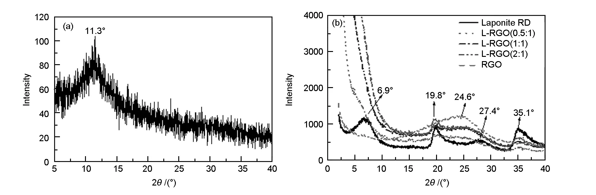
Fig. 4 XRD spectra of (a) GO, (b) RGO, laponite and L-RGO.
As a comparison, graphene reinforced laponite colloidal glass[8]showed graphene 2θpeaks at 4.5° and 3.5°, corresponding to the laponite/graphene ratios of 3 200∶1 and 360∶1, respectively. Graphene reinforced smectite clay composites[9]showed the interlayer space of about 1.4 nm with varying weight ratios of clay and graphene from 1∶1 to 16∶1. GO and laponite composites[11]showed 2θpeaks ranging from 10° to 11°, coming from the stacking of GO, with the laponite/GO ratios from 1∶19 to 1∶3. Although the above-mentioned reports had different highlighted points, a co-stacking structure between graphene layers and silicate layers was presented. This paper emphasised on preventing the graphene layers from re-stacking and co-stacking by the intercalation of laponite, which was the reason for the stable dispersion of L-RGO samples. Noting that our method was facile and efficient, involving no chemical functionalization and very little chemical waste, it could be promising for industrial applications.
An intercalation structure between laponite and RGO was suggested for L-RGO samples. A schematic drawing of the evolution and the intercalation structure of RGO and L-RGO is presented in Fig. 5, taking into consideration the size difference and electrostatic charge on the surface of RGO and laponite. GO had an interlayer spacing of 0.78 nm, which was presumably due to a one-molecule-thick layer of water entrapped between the GO layers through a hydrogen bond with the oxygen-containing functional groups[16, 17]. Upon reduction, the oxygen-containing functional groups were partially eliminated, and thus the entrapped water content was decreased. Therefore, interlayer space of RGO was reduced to 0.36 nm, which was close to the theoretical graphitic interlayer space. Laponite layers had a diameter of about 25 nm and a thickness of 1 nm, as revealed by the supplier. After hydrolysis, laponite layer was negatively charged on its surface and positively charged on its edge. The electrostatic attraction between the surface and the edge of the laponite led to the formation of the house-of-cards structure in laponite colloid[18]. RGO had a diameter ranging from 2-40 μm and a thickness of 1 nm[4, 19]. Owning to the remaining oxygen-containing functional groups, RGO was negatively charged. The electrostatic attraction happened between the RGO layers and the edge of the laponite for L-RGO samples, while the electrostatic repulsion happened between RGO and the surface of laponite. RGO was flexible while laponite was relatively rigid. Therefore, the laponite particle “stood” between the neighboring RGO layers, which provided steric hindrances between RGO layers and prevented the RGO from re-stacking/agglomeration. The intercalation structure attributed to the disappearance of RGO (002) peak, as shown in Fig. 4b, as well as the stability of L-RGO aqueous dispersion (Fig. 1).
The BET surface areas of laponite, RGO and L-RGO are listed in Table 1. The BET surface area of laponite was measured as 346 m2/g, which was close to the 330 m2/g as disclosed by the supplier. RGO’s surface area was about 435.6 m2/g. The L-RGO samples’ surface area was significantly higher than the values of laponite or RGO alone. The L-RGO (1∶1) showed the highest surface area, which was 34.4% higher than laponite and 17.6% higher than RGO. The difference in BET surface areas between L-RGO (1∶1) and L-RGO (2∶1) was marginal. The increase of BET surface area was consistent with the disappearance of RGO (002) peak as shown in the XRD patterns (Fig. 4b). The re-stacking/agglomeration of RGO layers is the main reason why the surface area of RGO is significantly lower than the theoretical value. The intercalation structure between laponite and RGO, as proposed in Fig. 5, prevented the re-stacking of RGO layers, which explained the increased surface areas for L-RGO samples.
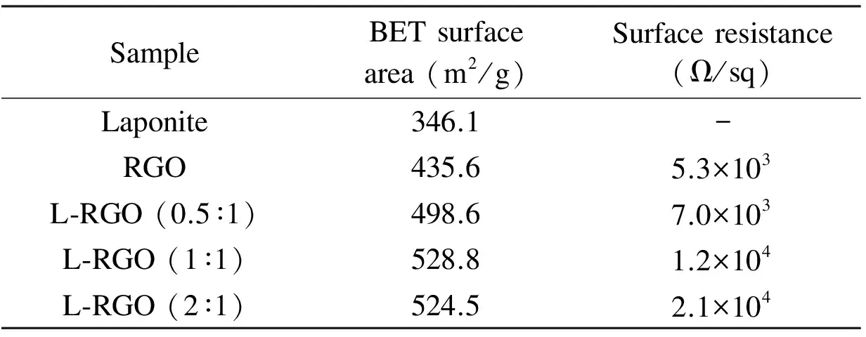
Table 1 Comparison of BET surface area and surface resistance.
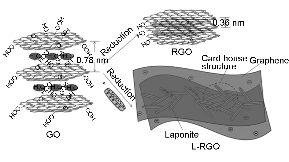
Fig. 5 Schematics of the evolution and the structure for RGO and L-RGO samples.
The dark field TEM image and corresponding element mapping of Al, Mg, Na, Si are shown in Fig. 6 to investigate the distribution of laponite and RGO in L-RGO (1∶1) sample. The elements Al, Mg, Na and Si came from laponite clay. The element mapping demonstrated the uniform distribution of laponite clay particles. The dark field TEM image in Fig. 6a shows a flocculent-like laponite clay, corresponding to the house-of-cards structure of laponite. By increasing the magnification, the bright field images (Fig. 7) shows that the laponite particles are supported by RGO layers. The laponite particles were identified from the image by its layered structure and diameter range, which were highlighted by white circles. The schematic illustration in Fig. 5 was justified by the TEM observation.
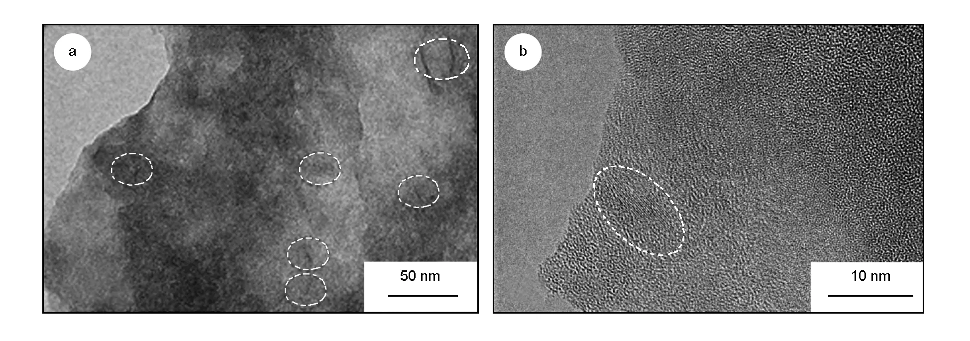
Fig. 7 TEM bright field images of L-RGO (1∶1) with different magnifications. The laponite particles were highlighted by circles.
The sheet resistances of the RGO and L-RGO samples are listed in Table 1. The laponite is electrically insulating, so the sheet resistance of L-RGO samples increased with the increasing content of laponite. We reported previously that the chemically functionalized RGO, which was prepared using titanate coupling agent and measured in a similar way, had the lowest sheet resistance of 1.1×10⁵Ω/sq[4]. As a comparison, the physically intercalated L-RGO (1∶1) had a sheet resistance of 1.2×10⁴Ω/sq, which was almost one order of magnitude lower than the chemically functionalized RGO.
4 Conclusions
The exfoliated graphene layers tended to re-stack/agglomerate upon the reduction of GO and showed a (002) peak in XRD pattern, which enventually led to agglomeration and precipitation. A physical intercalation method was studied. The RGO aqueous dispersion were stablized by the addition of a certain amount of laponite clay. Both the graphene layers and laponite layers were non-stacking, as proven by the disappearence of thed002andd001peaks of RGO and laponite using XRD patterns. An intercalation mechanism was proposed between graphene layers and laponite. The TEM observations indicated the uniform distribution of laponite clay particles on RGO. The surface area of the L-RGO (1∶1) was significantly increased by 17.6%, comapred to RGO. Compared with the chemically functionalized RGO, the surface resistance of physically intercalated RGO was about one order of magnitude lower. The one-step reduction and dispersion method studied in this paper was efficient and environmental friendly, which could be employed in mass production of RGO dispersions for versatile applications.
[1] Li D, Mueller M B, Gilje S, et al. Processable aqueous dispersions of graphene nanosheets[J]. Nat Nanotechnol, 2008, 3: 101-105.
[2] Stankovich S, Piner R D, Chen X, et al. Stable aqueous dispersions of graphitic nanoplatelets via the reduction of exfoliated graphite oxide in the presence of poly(sodium 4-styrenesulfonate)[J]. J Mater Chem, 2006, 16: 155-158.
[3] Yang H, Li F, Shan C, et al. Covalent functionalization of chemically converted graphene sheets via silane and its reinforcement[J]. J Mater Chem, 2009, 19: 4632-4638.
[4] Li J, Yang Z, Qiu H, et al. Microwave-assisted simultaneous reduction and titanate treatment of graphene oxide[J]. J Mater Chem A, 2013, 1: 11451-11456.
[5] Lotya M, Hernandez Y, King P J, et al. Liquid phase production of graphene by exfoliation of graphite in surfactant/water solutions[J]. J Am Chem Soc, 2009, 131: 3611-3620.
[6] Grandjean J, Laszlo P. Microdynamics of exchangeable lithium and sodium ions in laponite gels[J]. J Magn Reson, 1991, 92: 404-408.
[7] Loginov M, Lebovka N, Vorobiev E. Laponite assisted dispersion of carbon nanotubes in water[J]. J Colloid Interface Sci, 2012, 365: 127-136.
[8] Alhassan S M, Qutubuddin S, Schiraldi D A.Graphene arrested in laponite-water colloidal glass[J]. Langmuir, 2012, 28: 4009-4015.
[9] Nethravathi C, Viswanath B, Shivakumara C, et al. The production of smectite clay/graphene composites through delamination and co-stacking[J]. Carbon, 2008, 46: 1773-1781.
[10] Zhang C, Tjiu W W, Fan W, et al. Aqueous stabilization of graphene sheets using exfoliated montmorillonite nanoplatelets for multifunctional free-standing hybrid films via vacuum-assisted self-assembly[J]. J Mater Chem, 2011, 21: 18011-18017.
[11] Yoo J, Lee S B, Lee C K, et al. Graphene oxide and laponite composite films with high oxygen-barrier properties[J]. Nanoscale, 2014, 6: 10824-10830.
[12] Spyrou K, Potsi G, Diamanti E K, et al. Towards novel multifunctional pillared Nanostructures: Effective intercalation of Adamantylamine in graphene oxide and smectite clays[J]. Adv Funct Mater, 2014, 24: 5841-5850.
[13] Bagri A, Mattevi C, Acik M, et al. Structural evolution during the reduction of chemically derived graphene oxide[J]. Nat Chem, 2010, 2: 581-587.
[14] Pálková H, Madejová J, Zimowska M, et al. Laponite-derived porous clay heterostructures: II. FTIR study of the structure evolution[J]. Micropor Mesopor Mat, 2010, 127: 237-244.
[15] Daniel L M, Frost R L, Zhu H Y. Edge-Modification of Laponite with Dimethyl-octylmethoxysilane[J]. J Colloid Interface Sci, 2008, 321: 302-309.
[16] Aboutalebi S H, Gudarzi M M, Zheng Q B, et al. Spontaneous formation of liquid crystals in ultralarge graphene oxide dispersions[J]. Adv Funct Mater, 2011, 21: 2978-2988.
[17] Medhekar N V, Ramasubramaniam A, Ruoff R S, et al. Hydrogen bond networks in graphene oxide composite paper: structure and mechanical properties[J]. ACS Nano, 2010, 4: 2300-2306.
[18] Avery R G, Ramsay J D F. Colloidal properties of synthetic hectorite clay dispersions: II. light and small angle neutron scattering[J]. J Colloid Interface Sci, 1986, 109: 448-454.
[19] YANG Z, ZHENG Q, QIU H, et al. A simple method for the reduction of graphene oxide by sodium borohydride with CaCl2as a catalyst[J]. New Carbon Materials, 2015, 30: 41-47.
猜你喜欢
今日农业(2022年15期)2022-09-20
上海理工大学学报(2021年3期)2021-07-20
学生导报·高中版(2021年19期)2021-06-28
无机材料学报(2020年1期)2020-02-10
上海理工大学学报(社会科学版)(2019年4期)2020-01-01
上海理工大学学报(社会科学版)(2019年2期)2019-07-12
大众文艺(2019年3期)2019-01-24
学校教育研究(2018年1期)2018-10-21
浙江大学学报(工学版)(2016年2期)2016-06-05
中国塑料(2016年11期)2016-04-16