
Overview of SPH-ALE applications for hydraulic turbines in ANDRITZ Hydro*
2018-04-13 12:03RentschlerMarongiuNeuhauserParkinson
水动力学研究与进展 B辑 2018年1期
M. Rentschler, J.C. Marongiu, M. Neuhauser, E. Parkinson
Overview of SPH-ALE applications for hydraulic turbines in ANDRITZ Hydro*
M. Rentschler, J.C. Marongiu, M. Neuhauser, E. Parkinson
,,,
Over the past 13 years, ANDRITZ Hydro has developed an in-house tool based on the SPH-ALE method for applications in flow simulations in hydraulic turbines. The initial motivation is related to the challenging simulation of free surface flows in Pelton turbines, where highly dynamic water jets interact with rotating buckets, creating thin water jets traveling inside the housing and possibly causing disturbances on the runner.The present paper proposes an overview of industrial applications allowed by the developed tool, including design evaluation of Pelton runners and casings, transient operation ofPelton units and free surface flows in hydraulic structures.
Pelton turbine, two-phase folw, smoothed particle hydrodynamics (SPH), arbitrary Lagrange-Euler (ALE)
Introduction
The Pelton turbine is a hydraulic impulse machine that is best adapted for high head (from 200 m to around 2000 m)and low discharge installations (up to 50 m3/s). The largest units worldwide of BIEUDRON in Switzerland can deliver up to 420MW each, thanks to a water head of more than 1800 m. The main components of a Pelton turbine are the distributor, the injectors (up to 6), the runner and the housing (Fig. 1). While the flow is confined in the distributor and injectors, a free jet of water exits from the injectors’ nozzles and a free surface flow develops in the rotating runner and the housing. The runner is composed of buckets whose design is of primary importance for the proper conversion of kinetic energy of water jets into mechanical energy of the turbine shaft. However each component influences the overall performance of the machine. Consequently each com-ponent is analysed with numerical simulation.
Components of a Pelton turbine involving an internal flow can be simulated with state of the art mesh-based solvers, giving a good prediction of their behaviour[1, 2].These numerical approaches can also represent the free surface boundary condition, either implicitlythroughatwo-phasemodeltreatingthefree surfaceasaninterfacebetweenphases[3, 4],orexpli- citly through single phase models as for example when using deformable meshes[5, 6].It is technically feasible to simulate free surface flows inside a Pelton turbine with classical mesh-basedCFD tools. How-ever a proper tracking of the water inside the housing is very demanding, asmesh-based techniques natu-rally diffuse the free surface. Moreover, the meshing of a Pelton casingrequires time and expertise, while mesh quality can strongly influence the numerical flow. Theseintrinsic characteristics push classical CFD tools to the limit of their cost-effectiveness.

Fig. 1 (Color online) Exemplary layout of 2 units of 2-jet hori- zontal Pelton turbine
The SPH approach presents intrinsically attrac-tive features for the proper handling of free surface flows in Pelton turbines. Its complete mesh-free nu-merical stencil offers great flexibility and robustness for highly distorted media. The ability of solving free surface flows with calculation points only in the liquid phase can trigger great computational costs savings when the liquid occupies only a small volume in the simulation domain. For these reasons, ANDRITZ Hydro has been developing along the last 13 years an in-house simulation tool based on the SPH-ALE numerical method. The main features of this method will be recalled in Section 1. The tool is nowadays embedded in the design and verification processes of Pelton turbine components. Section 2 will present some applications illustrating the usage of the mesh-less approach for hydraulic turbines.
1. SPH-ALE method
1.1 Arbitrary Lagrange-Euler description

1.2 System of discrete equations


(4)

Equations(3) and (4) translate the mass and momentum conservation, respectively. It should be noted that these two equations involve convective mass and momentum flux terms which do not neces-sarily vanish even when adopting a Lagrangian trans-port velocity. As a consequence the SPH-ALE method allows variations of particles’ mass, contrarily to the classical SPH approach where particles have a constant mass. Nevertheless both approaches conserve mass globally.
The system requires an equation of state to relate pressure and density, the popular so-called Tait equa-tion is used

1.3 Computing particle interactions

There are numerous Riemann solvers that can be used efficiently and equivalently. Experience has shown that for weakly compressible cases, the exact solver is not necessary and linearized solvers are sufficient. Pre-conditioning techniques can be intro-duced to improve the quality of results in regions with very low dynamics[9].
A simple linear Riemann solver can be written as:


1.4 Time integration
The system of Eqs.(1) to (4) is updated with an explicit time integration scheme. For stability and accuracy reasons, 3rd and 4th order Runge-Kutta schemes are favoured.
1.5 High order schemes
1.5.1 High order numerical fluxes


However this approach suffers the limited accuracy of the SPH approximation of field gradients Eq. (8) and further improvements to the solution can be obtained by replacing SPH with moving least squares (MLS) approximates for the field gradient. Indeed MLS not only enforce accurate computation of the gradient of a function (Fig. 3) but also allows higher order (polynomial) representation of functions. Difficulties arise from the possibly disordered or truncated set of particles over which the MLS methodology is applied.In the frame of SPH-ALE it is necessary to implement order and space adaptation procedures so that stability and robustness are enforced (the detailed development and validation of these procedures can be found in Ref. [11]).

Fig. 3 Simulation of a water jet impacting a flat plate in 2-D
1.5.2 High order flux summation
Limitations highlighted above about the low accuracy of the SPH approximation of gradients Eq. (8) are valid also for the SPH divergence operators appearing in Eqs. (2)-(4) and which are key ingre- dients for the summation of numerical fluxes. In particular, and despite the use of high order numerical fluxes, the overall convergence order of the method is not enforced[12]. It is possible to derive divergence operators from the MLS methodology fulfilling completeness requirements and restoring the global convergence order of the complete method.
Numerical experiments have demonstrated the capability of the high order approach to improve the quality of results. In particular it was observed a reduction in both the numerical viscosity and the noise of the pressure field (Fig. 3).
1.5.3 Boundary conditions
The general approach of boundary conditions in SPH-ALE is to account for their contribution in the flux summation through a surface integral term. This is rooted in the derivation of gradient and divergence operators with SPH


Boundary fluxes are computed with partial Riemann solvers in the case of wall boundary con- ditions[9]. Open boundaries (inlet and outlet) are managed according a Non ReflectingCharacteristic Boundary Condition derived from Ref. [12].
2. Free surface applications for hydraulic turbines
2.1 Hydraulic and mechanical assessment of Pelton runners
A proper design procedure of a Pelton runner aims at maximizing the hydraulic efficiency while ensuring safety and reliability of operation. On the one side thinner buckets are known to deliver a higher efficiency but on the other side thinner structures are submitted to higher stresses. Therefore the hydraulic engineer needs to make a trade-off between the optimal hydraulic design and the fatigue that limits the lifetime of a runner.

Fig. 4 Design loop based on CFD.FEM evaluation

Fig. 5 (Color online) Initial configuration of the jet and buckets
A complete numerical evaluation has been deve- loped that combines the prediction of hydraulic performance with SPH-ALE and the prediction of mechanical stresses in the bucket with Finite Element Analysis. This evaluation is fully automatic including meshing and post-processing. At the end of the process an internal report is generated to document the result. (seeFig.4)
一是加强培训和实地考察。除了对医务人员、教育工作者加强人才交流外,还应强加对村党组书记、贫困村致富带头人、企业经营管理者的培训、跟班进修和实地考察,全面学习东南沿海发达地区先进的发展理念、生产经营模式、医疗和教育管理经验及技术,进一步开阔眼界、启迪思维、加深交流、提升素质。二是加强技术指导。邀请连江县农业技术方面的专家到陇西县开展种植、养殖等方面的技术培训及指导,帮助提高陇西县专业技术人才的综合素养和产业发展水平。
The typical configuration is composed of a runner sector (four to six buckets) fed with one water jet (Fig. 5). A symmetry condition is imposed at the mid-plane of the runner. Only possibly wetted sur- faces are included in the simulation. The simulation is done in pure Lagrangian mode and only the liquid phase is discretized.
To predict the stresses in the runner, it is neces- sary to sufficiently resolve the flow to predict local pressures. This pressure distribution is then used as a boundary condition for a structural calculation to predict the stresses in the runner.
The pressure maps as an outcome of the SPH-ALE simulation were validated against measurements. For those measurements a model scale runner was instrumented with pressure sensors.

Fig. 6 (Color online) Validation of the pressure signals from CFD compared with model measurements
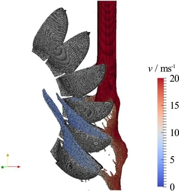
Fig. 7 (Color online) Detailed flow in a Pelton runner as used in the design process

Fig. 8(Color online) Observing casing flow in a model test
Figure 6 shows the comparison of the experiment signal and the SPH-ALE result. The red dot is the position of the pressure sensor on the internal face of the bucket.
The pressure map is then used as a boundary condition for a FEM simulation that calculates the stresses for several positions of the runner/jet in a quasi-static approach. A safety factor is added to account for inertial effects due to the cyclic loading of the buckets.
The use of the SPH-ALE method reduces the calculation time from several days, with standard finite volumes methods to several hours using the SPH-ALE method. Due to the Lagrangian description no rotor-stator interface is necessary. A rotor-stator interface may be unstable for two-phase simulations. Robustness of the simulation process is essential for its usability in an industrial environment. Hydraulic designers require reliable and efficient tools delivering hydraulic and mechanical assessment results.Such a required robustness to simulate the flow in a Pelton bucket is difficultto achieve by a finite volume code.
2.2 Hydraulic assessment of Pelton casings
The flow in the casing of a Pelton turbine is an essential element in the overall efficiency of the turbine (see Fig.7). The visualization of the flow in the laboratory is a challenge due to the presence of bubbles in the water that makes the water opaque. Figure 8 illustrates the possible observations of a model test in the ANDRITZ Pelton laboratory. The impact zone of the water is indicated by the arrow.
Simulating the casing flow using finite volume methods is computationally very expensive as the free surface needs to be captured explicitly. A fine mesh is required to represent the details of free surface using finite volume methods. The computational effort to capture major features of the casing flow is in the order of magnitude of 105cpu h. This makes it impossible to be used in a project time frame.
The use of SPH-ALE decreases the simulation time to several days of simulation, which is affordable in the time-scale of a project. As a result the flow in the casing can be easily analysed in three dimensions (Fig. 9 and Fig. 10) and the casing can be adapted and optimized by inserting steel plates that guides the water out of the casing.

Fig. 9 (Color online) SPH-ALE simulation of casing flows in a horizontal 2-jets Pelton unit

Fig. 10 (Color online) SPH-ALE simulation of a casing flows in a vertical 2-jets Pelton unit
The velocity range for those simulations span two orders of magnitude, from above 100 m/s in the jets to below 1 m/s on the casing walls. For the low Mach numbers, numerical dissipation easily domi- nates the flow and imposes the use of higher order schemes to prevent numerical artefacts[13].
For Pelton turbines with vertical rotation axis, inserts play a minor role due to axial or cyclic symmetry of the casing. The overall flow can however create water flowing back on the runner, which reduces the hydraulic efficiency of the machine. Detailed simulations are necessary to verify that the flow in the casing will not impact in a negative way the efficiency of the machine (see Fig. 10). Especially for rehabilitation projects, the prediction of the casing flow is of value, as often no experience is available with some types of vertical Pelton machine casings.
2.3 Deflector simulation
In case of an emergency a deflector deviates the jet away from the Pelton runner in order to prevent further acceleration of the runner. Although this device is very simple and does not require a complex hydraulic engineering in itself, it creates a high energy flow in the casing which might create leakage or damages on the installation.

Fig. 11 (Color online) Flow analysis of a deflecting security device and its interaction with a Pelton runner
Especially when effects far from the deflector are of interest, then the Lagrangian character of the SPH-ALE method permits to simulate those flows at reasonable costs. This leads to some standard checks during design phase of the Pelton turbine, to prevent issues during commissioning.
One example for such a standard check is the simulation of the deflected water jet hitting the following deflector. During the commissioning of a refurbished installation, strong vibrations were obser- ved. To understand the phenomena, SPH-ALE simula- tion was used to simulate a system of deflectors (seeFig. 11 for a close-up view of the deflected jet andFig. 12 for the complete view of the six deflected jets and interactions with following injector).
It could be observed that the deflected water sheet from one deflector interacted slightly with the runner before hitting the next deflector. The impact of the water sheet slightly moved the next water sheet which then hit a third deflector and so on. The conclusion was to modify the roof of the injector in order to protect the deflectors from direct impacts from the previous deflector.
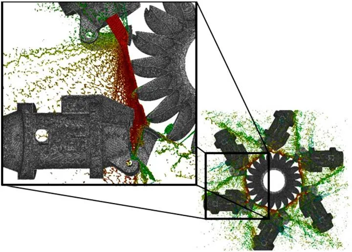
Fig. 12 (Color online) SPH-ALE simulation of runner and a system of deflectors for root cause analysis

Fig. 13 (Color online) SPH-ALE simulation of a braking jet impacting a rotating Pelton runner
2.4 Brake jet
To slow down the Pelton units quickly, they may be equipped with so-called braking jets that impact the runner in the opposite direction of the runner rotation. This normally is only meant to be a security device which should only be used in case of emergency (see Fig.13).
However this configuration may endanger the structural integrity because the relative velocity of the buckets and the braking jet is three times higher than the normal “driving” jet, and buckets are not designed to sustain loading on their rear side. In general the setup of the simulation is identical to what is pre- sented in Section 2.1. The only difference is that the direction of the jet is inverted.
The high velocity impact and high frequency pressure variations make it difficult to setup such a simulation with a commercial finite volume code. Very small time steps would be required to simulate this configuration, and consequently the correspon- ding computational load with finite volumes methods would be much higher than with SPH-ALE.
Also for that application the pressure fields obtained from the SPH-ALE simulation are trans- ferred as boundary conditions to the FE solver to calculate the stresses in the runner, even if this application is on the limit of the applicability of the quasi static FEM approach.
2.5 Start-up of a Pelton unit
Since the implementation of SPH-ALE on GPU the start-up of a Pelton machine including the casing can be simulated. At low rotational speed, the water leaving the runner has a high velocity and a direction which is not the one obtained at nominal speed, and therefore creates high stresses in parts of the machine. At higher runner speed, the stresses due to water impacts on static components reduce, but the periodi- city of the flow increase at the frequency of the “bucket passage frequency”, which creates a high number of cycles. For the structural integrity it is therefore not always evident which runner rotational speed generates the most critical solicitations. The simulation of the full start up sequence of the machine allows the quantitative structural analysis and allows the optimisation of the sequence to guarantee a given lifetime of the machine.
To obtain a fast acceleration of the runner it is of value to increase the power on the runner as fast as possible. The simulation (Fig. 14) of the start-up and the stresses in the runner are helpful to define a start-up scenario to accelerate the runner as fast as possible while keeping the stresses in an acceptable range.
SPH-ALE can also be used to study water intakesandother hydraulic structures of hydropower plants. Secondary flow structures like recirculation or vortices that may be present at the inlet of the penstock are carried down to the turbine units and may influence dramatically the overall performance and behaviour of the installation. For low head ma- chines the flow in the intake directly impacts the efficiency of the turbine.

Fig. 14 (Color online) Start-up of a Pelton machine

Fig. 15 (Color online) SPH simulation of an intake to a hydro power plant
The setup of the simulation of an intake of a Hydro power plant includes a detailed bathymetry of the river bed and a detailed CAE model of the installation (see Fig. 15). The discharge is imposed at the inlet and various outlet conditions may be imposed depending on the cases, including an artificial weir which may be used downstream to control the water height close to the outlet.
As the domain occupied by the volume of liquid is compact and the free surface is almost static in normal flow conditions, such a flow simulation could efficiently be done using a finite volume code. How- ever in that case the meshgeneration process might be a time consuming interactivework for a calculation engineer. SPH-ALE can propose an alternative app- roach requiring less involvement from simulation engineers.
3. Conclusion
The development of the SPH-ALE over the last 13 years has been presented with an emphasis on its applications to hydraulic machinery and especially for Pelton turbines. For the Pelton turbines this new method has become an integral part of the design process. The method has proven its accuracy and robustness during the last years by being applied to numerous projects in this industrial environment. Especially the interaction of this tool with structural analysis has shown its benefit for the projects. The implementation of the method on GPU accelerated the overall execution time and helped to further extend the field of applications and the usability in industrial projects.
[1] ParkinsonE., Bissel C., Popescu E. et al.Upgrading Pelton turbines of LOTRU-CIUNGET HPP, Romania [C]., Prague, Czech Republic, 2011.
[2] ParkinsonE, RentschlerM., LaisS. et al. Life cycle of a Pelton runner [C]., Colombo, Sri Lanka, 2014.
[3] SussmanM., SmerekaP., OsherS.A level set approach for computing solutions to incompressible two-phase flow [J]., 1994, 114(1): 146-159.
[4] HirtC.W., NicholsB.D. Volume of fluid (VOF) method for the dynamics of free boundaries [J]., 1981, 39(1): 201-225.
[5] HirtC. W., AmsdenA., CookJ.L.An Arbitrary Lagran- gian-Eulerian computing method for all flow speeds [J].,1997, 135(2): 203-216.
[6] MünchC., AusoniP., BraunO. et al. Fluid-structure coupling for an oscillating hydrofoil [J]., 2010, 26(6): 1018-1033.
[7] DoneaJ., HuertaA., Ponthot J. et al. Arbitrary Lagran- gian-Eulerian methods (SteinE., DeBorst R., HughesT. Encyclopedia of computational mechanics) [M]. Chicester, UK: John Wiley and Sons, 2004.
[8] VilaJ.P.On particle weighted methods and smoothed particle hydrodynamics [J]., 1999, 9(2): 161-210.
[9] MarongiuJ.C., LeboeufF., CaroJ. Free surface flows simulations in Pelton turbines using an hybrid SPH-ALE method [J]., 2010, 48(Sup1): 40-49.
[10] Van LeerB.Towards the ultimate conservative difference scheme V: A second-order sequel to Godunov’s method [J]., 1979, 32(1): 101-136.
[11] RenautG.A., MarongiuJ.C., AubertS. High-order and adaptive procedures for SPH-ALE simulations based on moving least squares method [C]., Parma, Italy, 2015.
[12]SelleL., NicoudF., PoinsotT. Actual impedance of nonreflecting boundary conditions: Implications for com- putation of resonators [J]., 2004, 42(5): 958-964.
[13] RentschlerM., NeuhauserM., MarongiuJ.C. et al. Under- standing casing flow in Pelton turbines by numerical simulation [J]., 2016, 49(2): 022004.
(October 22, 2017, Accepted December 9, 2017)
©China Ship Scientific Research Center 2018
M. Rentschler (1973-), Male, Ph. D.
M. Rentschler,
E-mail:martin.rentschler@andritz.com
猜你喜欢
海峡姐妹(2021年10期)2021-11-15
皮革制作与环保科技(2020年14期)2020-03-17
戏剧之家(2018年23期)2018-11-26
红土地(2018年9期)2018-02-16
市场周刊(2017年1期)2017-02-28
文化交流(2016年10期)2016-10-27
现代经济信息(2016年4期)2016-06-20
油气田地面工程(2014年5期)2014-03-09
现代企业文化·理论版(2008年1期)2008-03-22
中国中小企业(2007年5期)2007-05-26

- 水动力学研究与进展 B辑的其它文章
- Analysis of the hydrological safety of dams combining two numerical tools: Iber and DualSPHysics *
- Impacts of bridge piers on water level during ice jammed period in bend channel–An experimental study *
- DualSPHysics: A numerical tool to simulate real breakwaters *
- SPH numerical investigation of the characteristics of an oscillating hydraulic jump at an abrupt drop *
- Five-equation and robust three-equation methods for solution verification of large eddy simulation *
- High-speed water impacts of flat plates in different ditching configuration through a Riemann-ALE SPH model *