
TiO2纳米纺锤体负载Pt 在氧还原反应中的应用*
2018-05-09 10:30彭桂明巫素琴彭全明BURKERTSeth杜瑞安余长林STARAlexander
新能源进展 2018年2期
彭桂明,巫素琴,彭全明,BURKERT Seth C.,杜瑞安,余长林,STAR Alexander†
(1. 江西理工大学冶金与化学工程学院,江西 赣州 341000;2. 中国科学院可再生能源重点实验室,广州 510640;3. 广东工业大学材料与能源学院,广州 510006;4. 匹兹堡大学化学系,美国宾夕法尼亚州匹兹堡,15260)
0 Introduction
Catalysts play a critical role in fuel cells by accelerating oxidation of “fuels” at the anode and promoting oxygen reduction at the cathode to the levels required for practical application. So far, Pt has been the most efficient catalyst in fuel cells, although its high cost and limited reserve hampers its widespread application in industry. Alloying Pt with other abundant metals[1-3]and loading noble metal nanostructures on support materials[4-6]have been reported to lower catalyst cost while maintaining high catalytic activity. Among the widely investigated carbonaceous nanomaterials-supported catalysts, carbon nanomaterials suffer from severe corrosion and oxidation in practical application[7-9], which subsequently causes Pt migration and aggregation, resulting in decreases in both electrochemical surface area and catalytic activity[7]. Exploring efficient and low cost catalysts or corrosion-resistant catalyst support alternatives is of particular significance to reduce catalyst price and improve catalyst durability and activity.
To address the catalyst support corrosion issue,transition metal oxides have been used as alternatives to carbon nanomaterials as supports due to their low cost,abundance, and long-term stability[5-7]. Among these metal oxides, titanium dioxide (TiO2) has shown catalytic activity in oxygen reduction reaction (ORR) in both acidic and alkaline solutions[10-12]. In addition, the tremendous advances in TiO2nano-engineering in the past two decades enable the feasibility to afford TiO2with large specific area for active metals to anchor. However,one drawback of TiO2is its limited catalytic activity due to its poor electric conductivity. It is expected that the growth of noble metal nanoparticles onto TiO2not only overcomes the support corrosion, but also benefits the ORR activity of TiO2by affording efficient electron transport pathways.
Herein, anatase TiO2nanospindles were synthesized through a simple sol-gel method. And the corresponding anatase TiO2nanospindles were used as support for Pt growth to obtain TiO2-Pt catalyst for ORR. The catalyst stability and photocatalytic electrochemistry were discussed in this study subsequently.
1 Experimental
1.1 Synthesis of TiO2 nanospindles
TiO2nanospindles were synthesized through a facile environmentally friendly sol-gel method as following. 10 µL titanium isopropoxide (TTIP) was firstly injected into a 0.375 mol/L HCl aqueous solution. The mixture was then incubated at 90°C for 1 hour to synthesize nanospindles.TiO2nanospindles were collected by centrifugation, and were washed with water to remove the HCl residue. To avoid aggregation, the precipitate was collected via lyophylization. Calcination of the TiO2nanospindles was performed at 400°C in air for 0.5 hour. Control samples with different synthesis durations or different TTIP amounts were obtained following the same process.
1.2 Synthesis of TiO2 nanospindle supported Pt nanodots
Pt nanodots were deposited onto the obtained TiO2nanospindles via a similar method developed by Xia et al[13].Firstly, 2.5 mg TiO2nanospindles were dispersed into 2 mL ethylene glycol (EG), followed by heating at 110°C for 0.5 hour to remove the trace water. Then 0.5 mL PVP solution (40 mM in EG) and 0.5 mL H2PtCl6solution(80 mM in EG) were added into the above system. The obtained reaction mixture was kept at 110°C for 8 hours to allow for Pt deposition. The precipitate was collected through centrifugation and subsequently washed with ethanol and deionized water. Then the TiO2supported Pt catalyst was obtained.
1.3 Material characterization
X-ray diffraction (XRD) patterns were collected on a Bruker D8-Advance X-ray diffractometer. Low-resolution transmission electron microscopy (TEM) images were obtained with a Philips/FEI Morgagni at an accelerating voltage of 80 kV. High-resolution TEM (HRTEM) images were taken using JEOL 2100F microscope with an accelerating voltage of 200 kV. TEM samples were prepared by drop-casting an aqueous solution of the nanomaterial on a lacey carbon TEM grid (Pacific Grid-Tech)for low-resolution TEM imaging or on C-FLAT holey TEM grid (Electron Microscopy Sciences) for HRTEM imaging. Raman spectra were collected on a Reinshaw inVia Raman microscope at an excitation wavelength of 633 nm at 10% laser power (maximum 17 mW) with 15 s exposure time. Samples were dropcasted on a quartz slide and dried before characterization.
1.4 Electrochemical testing
Electrochemical experiments were performed using a CHI 7042 Bipotentiostat (CH Instruments, Austin, TX). A Pt wire electrode (CHI 115) and an Ag/AgCl (CHI 111,1 M KCl) electrode were used as the counter and reference electrode, respectively. The electrodes including the glassy carbon working electrode with its area of 0.09 cm2were purchased from CH Instruments, Austin, TX. For cyclic voltammogram (CV) tests, a catalyst ink composed of 1 mg/mL TiO2-Pt and 10 µL 25% Nafion was prepared.10 µL catalyst ink was drop-cast onto a glassy carbon electrode and was allowed to dry over before usage. ORR measurement was evaluated in O2saturated 0.1 mol/L KOH. To test the influence of UV light illumination on the ORR performance, UV light with its wavelength of 254 nm illuminated the working electrode during ORR performance test.
2 Results and discussion
Via the mehod in this report, ~40 nm long and ~15 nm wide TiO2nanospindles were obtained (Fig. 1a). To improve the crystallinity, the TiO2nanospindles underwent calcination in air at 400°C for 0.5 hour with their TEM images presented in Fig. 1b. Comparing with the nanospindles before calcination, 0.5 hour calcination at 400°C led to some deformation while the spindle morphology remained intact. In addition, several ~5 nm-sized voids and rough surfaces were observed on each nanospindle, which might be caused by the water loss and material crystallization during calcination process. The slightly size expansion could also be observed after calcination, which should be a result of the void formation in TiO2nanospinles and the different specific volumes for material before and after crystallization.

Fig. 1 TEM images of TiO2 nanospindles (a) before and (b)after calcination
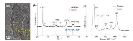
Fig. 2 (a) HRTEM image of a TiO2 nanospindle; (b) XRD pattern of the TiO2 nanospindles; (c) Raman spectra of the TiO2 nanospindles
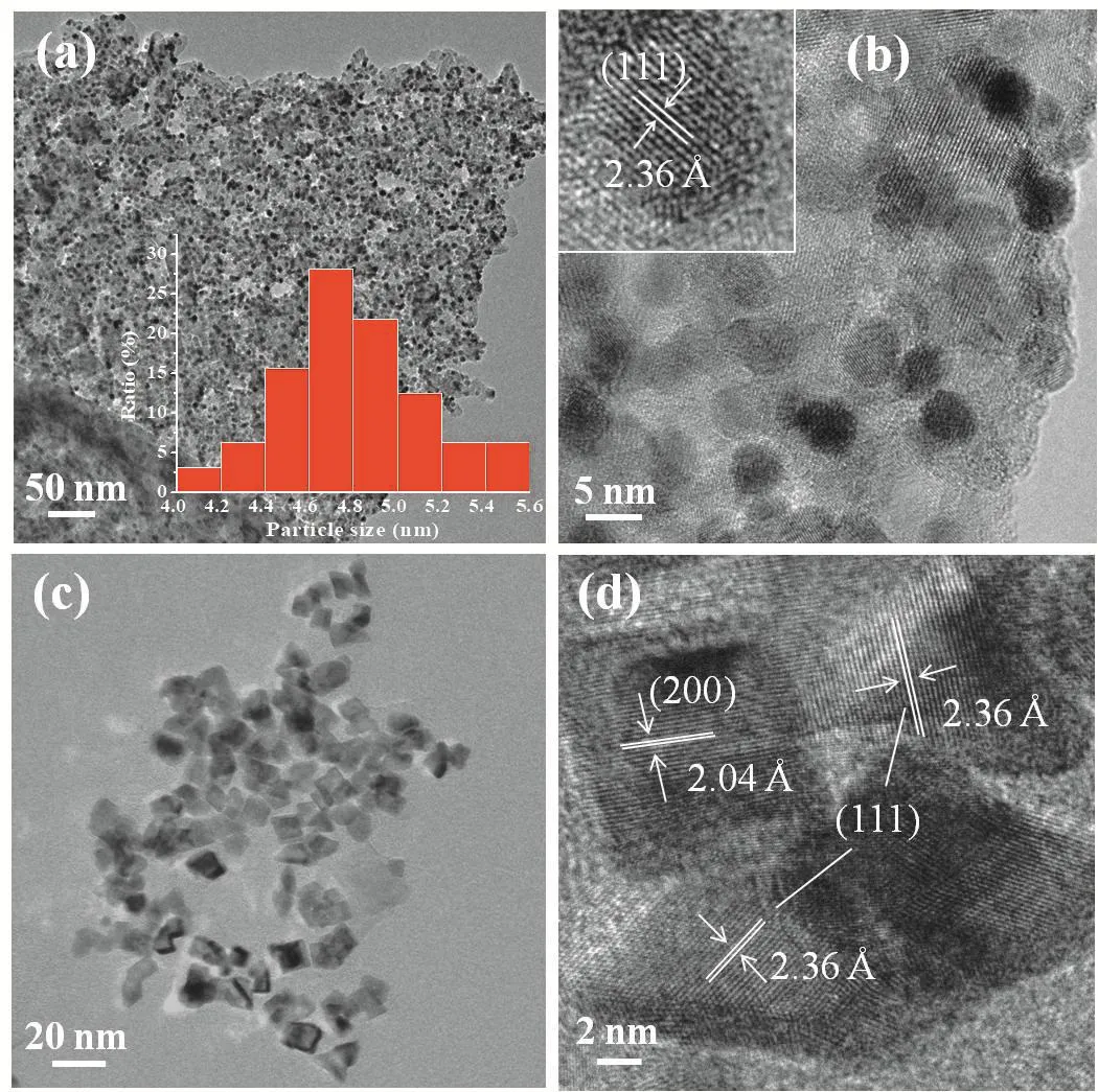
Fig. 3 (a) TEM and (b) HRTEM images of TiO2 nanospindles supported Pt nanodots; inset in panel (a) is the size distribution of the Pt nanodots; (c) TEM and (d) HRTEM images of free Pt nanoparticles synthesized in absence of TiO2 nanospindles
HRTEM, XRD, and Raman were adopted to characterize the obtained TiO2nanospindles. Lattice interspacing of 3.4 Å in HRTEM is well indexed to the (101) lattice plane of anatase TiO2(Fig. 2a). XRD measurement shows that the TiO2nanospindles are well indexed to the anatase phase of TiO2(Fig. 2b). Raman characteristic peaks at 145, 198, 400, 516, and 640 cm-1in Fig. 1c are assigned to main Egvibration peak, Eg, B1g, A1g, and Egmodes of anatase phase, respectively[14]. In addition to these anatase peaks, minor rutile characteristics at 244, 326, and 448 cm-1appear (Fig. 2c), in consistence with that observed in XRD pattern, which confirms the existence of small amounts of rutile TiO2in the powder.
TEM image of TiO2nanospindles supported Pt nanodots was shown in Fig. 3a. Apparently, uniform Pt dots with the sized narrowly centered at ~4.8 nm (inset in Fig. 3a) were evenly anchored onto the surface of TiO2nanospindles (Fig. 3(a, b)). The interspacing of 2.36 Å is assigned to (111) surface (Fig. 3b)[13]. Additionally, partial overlap of the Pt nanodots is observed, which is good for electrochemical catalytic activity by overcoming the inferior electrical conductivity of TiO2.
Furthermore, Pt nanodot morphology was found to be dependent on the presence of TiO2nanospindles. With the absence of TiO2nanospindles, while other conditions remained constant, polyhedral Pt nanoparticles around 10 nm were synthesized instead of round nanodots(Fig. 3(c, d)). The lattice interspacing of 2.36 Å and 2.04 Å are indexed to (111) and (200) of Pt, respectively[13]. The well-constructed Pt nanostructures may find wide applications due to their small size and large specific surface area; however, their potential applications are not included in this study. The Pt morphology difference with and without support material most likely originates from surface affinity of TiO2nanospindles for Pt and the precursor H2PtCl6, which affects the nucleus formation modes.
ORR performance of the TiO2-Pt catalyst and commercial catalyst C-Pt (10wt%) in O2saturated 0.1 mol/L KOH is presented in Fig. 4. The TiO2-Pt composite showed two prominent reduction peaks at -0.23 V and-0.42 V (versus Ag/AgCl) (Fig. 4a), which are contributed by both the Pt and TiO2, respectively. It is observed that the peak current at -0.23 V increased as more cycles are run, and is finally stabilized at 50 cycles. On the contrary,the reduction current from TiO2at -0.42 V decreased somewhat (inset in Fig. 4a). This might be because smaller Pt nanoclusters which initially sit on the surface of TiO2migrate towards the relative larger Pt nanodots during testing, leading to the enhanced ORR on the Pt surface. Meanwhile, the Pt nanocluster migration may deteriorate the electron transfer from TiO2, thus diminish the O2reduction taking place on the TiO2surface. It is also noted that ORR peak for Pt in TiO2-Pt is more negative than that of C-Pt catalyst (-0.23 V vs -0.19 V)(Fig. 4d), while TiO2peak remains almost unshifted at-0.42 V compared to the individual TiO2nanospindles[10].In addition, the peak current at -0.42 V in Fig. 4a(4 × 10⁻⁵A) is higher than that obtained on TiO2nanospindles from our previous report (2.6 × 10⁻⁵A)[10].Electrochemical impedance spectroscopy (EIS) was used to reveal the influence of the Pt growth on surface charge transport behavior. The EIS results show that the TiO2-Pt exhibits a much reduced charge transport resistance with respect to that of TiO2(Fig. 4b). The enhanced charge transport should be attributed to the partial overlap of the Pt nanodots on the TiO2nanospindle surface, which explains the ORR enhancement on TiO2nanospindles.
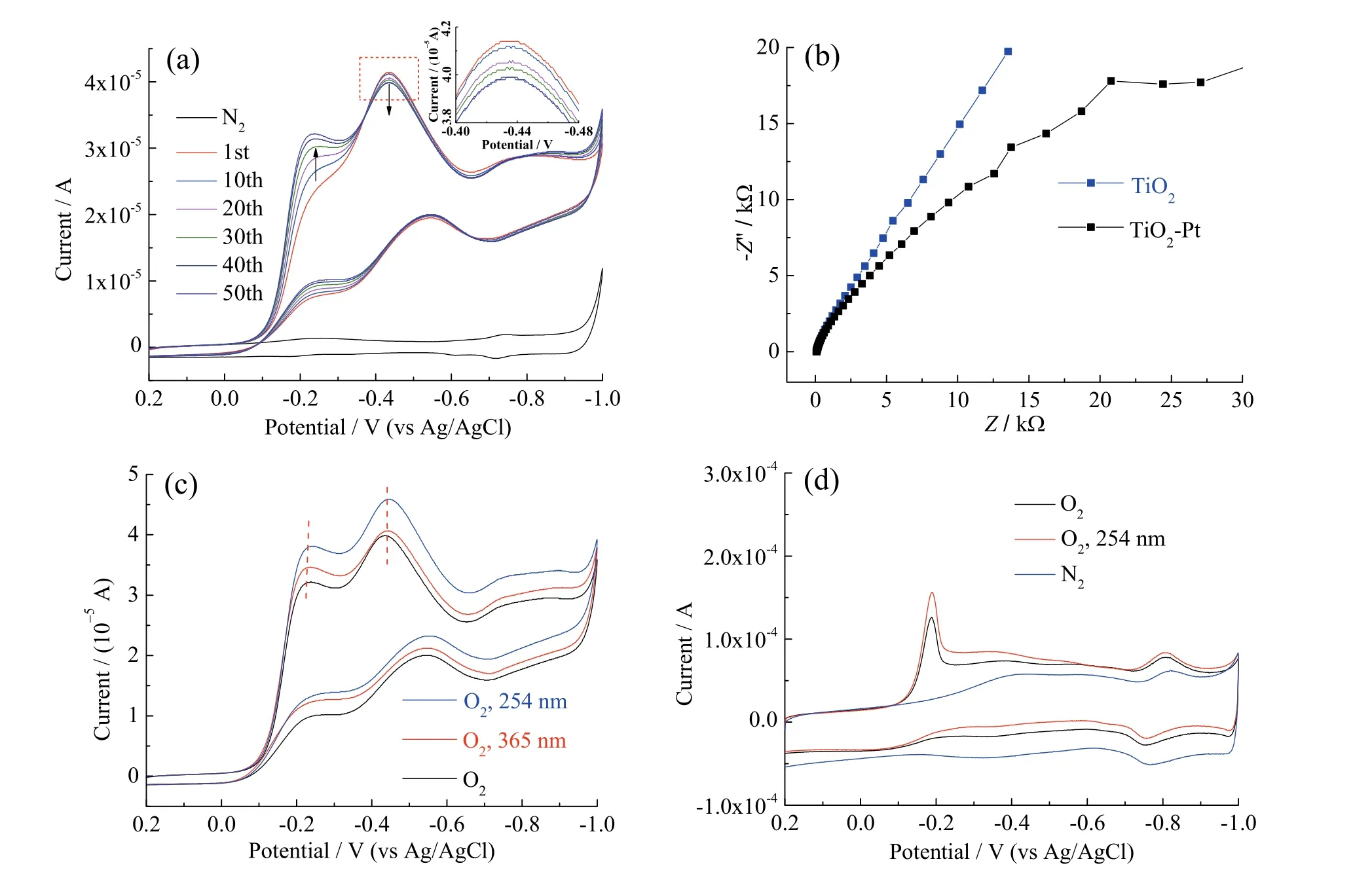
Fig. 4 (a) Cyclic voltammograms of the TiO2-Pt in O2 saturated 0.1 M KOH aqueous solution, inset is the zoom-up of the reduction peak at -0.42 V, the gray curve is obtained in N2 saturated 0.1 M KOH aqueous solution; (b) EIS of the TiO2-Pt and TiO2 electrodes at a bias of -0.42 V vs Ag/AgCl in O2 saturated 0.1 M KOH aqueous solution; (c, d) influence of UV light illumination on ORR, (c)TiO2-Pt, (d) commercial C-Pt
Influence of UV light on ORR performance of the TiO2-Pt was investigated. The irradiation of 365 nm UV light mainly increases the ORR reduction on Pt nanodots,while UV light of shorter wavelength, 254 nm, enhances both ORR performances on TiO2and Pt components(Fig. 4c). The ORR enhancement on the commercial C-Pt catalyst was also observed by shinning with 254 nm UV light (Fig. 4c). The results suggest that the Pt nanodots could absorb UV light by interband excitation[15], thus affording photogenerated electrons for ORR. The unparalleled ORR enhancement caused by 365 nm UV light might be arised from the possibly impure spectrum of the lamp (The spectrum is not determined. i. e. It is likely the lamp is not an absolute monochromatic source but with a range of wavelengths. This may lead to that part of the spectrum is beyond the absorption of TiO2, but within the response of Pt nanodots). In addition, the asymmetric enhancement by 365 nm UV light but almost equal increase when applying 254 nm UV light on both components implies the photo-generated electrons on TiO2can be hopped to the surface of Pt, but the electrons on Pt cannot jump back to TiO2. The negative shift of the ORR peaks upon UV light illumination in Fig. 4c is likely to arise from electron charging due to the humble electron transport of the TiO2, since no shift is found for C-Pt in Fig. 4d.
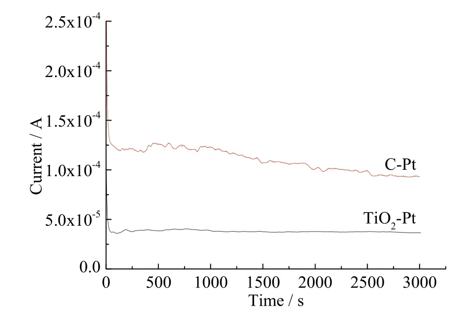
Fig. 5 Chronocurrent at the potential of -0.42 V vs Ag/AgCl of TiO2-Pt in O2 saturated 0.1 M KOH aqueous solution, and Chronocurrent of the commercial C-Pt (10wt%) catalyst at the potential of -0.19 V vs Ag/AgCl in O2 saturated 0.1 M KOH
Catalyst stability of the TiO2-Pt was evaluated by monitoring the ORR current at the potential of -0.42 V vs Ag/AgCl (Fig. 5). The results show that the current slightly fluctuates during the first 15 minutes and remains stable afterwards. No prominent ORR current decay is observed during 50 minutes-test. Unlike the TiO2-Pt catalyst, the chronocurrent of commercial C-Pt at -0.19 V showed 20% decay over 50 minutes (Fig. 5). The superior durability can be explained by the outstanding physical and chemical stability of the TiO2nanospindles which overcomes the catalyst support corrosion issue. It is worthwhile to note that, although the catalytic activity of the TiO2-Pt catalyst is still humble compared to that of the commercial C-Pt, it is envisioned that TiO2supported active metals for ORR can be a kind of promising long-term stable catalyst once the electric conductivity of the TiO2is further rationally designed and improved.
3 Conclusions
In conclusion, ~40 nm-long, ~15 nm-wide anatase TiO2nanospindles were used as support for Pt nanodots growth to afford a catalyst for ORR. The growth of round Pt nanodots was discussed and found to be relevant to the support material. Electrochemical evaluations showed the as-prepared TiO2-Pt exhibited two ORR peaks corresponding to the two different components, with the ORR on TiO2is enhanced after Pt deposition. EIS results suggest that the enhancement in ORR on TiO2is attributed to the accelerated charge transport afforded by the partial overlapped Pt nanodots. Moreover, UV light is found to be able to promote the ORR on both TiO2and Pt in a one-way photo-generated electron transport fashion (from TiO2to Pt) within the two components. The stability test proved that the TiO2-Pt exhibited superior stability over the commercial C-Pt catalyst.
Reference:
[1]DING L X, WANG A L, LI G R, et al. Porous Pt-Ni-P composite nanotube arrays: Highly electroactive and durable catalysts for methanol electrooxidation[J].Journal of the American chemical society, 2012, 134(13):5730-5733. DOI: 10.1021/ja212206m.
[2]CHEN C, KANG Y, HUO Z, et al. Highly crystalline multimetallic nanoframes with three-dimensional electrocatalytic surfaces[J]. Science, 2014, 343(6177):1339-1343. DOI: 10.1126/science.1249061.
[3]CUI Z M, CHEN H, ZHAO M T, et al. Synthesis of structurally ordered Pt3Ti and Pt3V nanoparticles as methanol oxidation catalysts[J]. Journal of the American chemical society, 2014, 136(29): 10206-10209. DOI:10.1021/ja504573a.
[4]LIN C, SONG Y, GAO L, et al. Oxygen reduction Catalyzed by Au-TiO2nanocomposites in alkaline media[J]. ACS applied materials & interfaces, 2013,5(24): 13305-13311. DOI: 10.1021/am404253b.
[5]HUANG S Y, GANESAN P, POPOV B N.Electrocatalytic activity and stability of titania-supported platinum-palladium electrocatalysts for polymer electrolyte membrane fuel cell[J]. ACS catalysis, 2012,2(5): 825-831. DOI: 10.1021/cs300088n.
[6]CHAUHAN S, MORI T, MASUDA T, et al. Design of low Pt concentration electrocatalyst surfaces with high oxygen reduction reaction activity promoted by formation of a heterogeneous interface between Pt and CeOxnanowire[J]. ACS applied materials & interfaces,2016, 8(14): 9059-9070. DOI: 10.1021/acsami.5b12469.
[7]HUANG S Y, GANESAN P, PARK S, et al.Development of a titanium dioxide-supported platinum catalyst with ultrahigh stability for polymer electrolyte membrane fuel cell applications[J]. Journal of the American chemical society, 2009, 131(39): 13898-13899. DOI:10.1021/ja904810h.
[8]SHAO Y Y, YIN G P, GAO Y Z. Understanding and approaches for the durability issues of Pt-based catalysts for PEM fuel cell[J]. Journal of power sources, 2007,171(2): 558-566. DOI: 10.1016/j.jpowsour.2007.07.004.
[9]SCHMITTINGER W, VAHIDI A. A review of the main parameters influencing long-term performance and durability of PEM fuel cells[J]. Journal of power sources,2008, 180(1): 1-14. DOI: 10.1016/j.jpowsour.2008.01.070.
[10]PENG G M, ELLIS J E, XU G, et al. In situ grown TiO2nanospindles facilitate the formation of holey reduced graphene oxide by photodegradation[J]. ACS applied materials & interfaces, 2016, 8(11): 7403-7410. DOI:10.1021/acsami.6b01188.
[11]TSUJIKO A, ITOH H, KISUMI T, et al. Observation of cathodic photocurrents at nanocrystalline TiO2film electrodes, caused by enhanced oxygen reduction in alkaline solutions[J]. The journal of physical chemistry B, 2002, 106(23): 5878-5885. DOI: 10.1021/jp012144l.
[12]MENTUS S V. Oxygen reduction on anodically formed titanium dioxide[J]. Electrochimica acta, 2004, 50(1):27-32. DOI: 10.1016/j.electacta.2004.07.009.
[13]FORMO E, LEE E, CAMPBELL D, et al.Functionalization of electrospun TiO2nanofibers with Pt nanoparticles and nanowires for catalytic applications[J].Nano letters, 2008, 8(2): 668-672. DOI: 10.1021/nl073163v.
[14]WANG H F, CHEN L Y, SU W N, et al. Effect of the compact TiO2layer on charge transfer between N3 dyes and TiO2investigated by raman spectroscopy[J]. The journal of physical chemistry C, 2010, 114(7):3185-3196.DOI: 10.1021/jp908233h.
[15]SHIRAISHI Y, SAKAMOTO H, SUGANO Y, et al.Pt-Cu bimetallic alloy nanoparticles supported on anatase TiO2: highly active catalysts for aerobic oxidation driven by visible light[J]. ACS nano, 2013, 7(10): 9287-9297.DOI: 10.1021/nn403954p.
猜你喜欢
中国机械工程(2022年18期)2022-10-08
现代苏州(2022年14期)2022-08-05
建材发展导向(2020年16期)2020-09-25
中国机械工程(2019年19期)2019-10-28
中国机械工程(2019年11期)2019-06-13
中国机械工程(2019年4期)2019-03-06
小学生优秀作文(低年级)(2018年11期)2018-11-14
求是学刊(2017年6期)2018-01-10
老友(2011年3期)2011-06-09
创新时代(2009年10期)2009-12-21
