
Preliminary design of high power magnet converter for CRAFT
2020-05-06 05:59ZhongmaWANG王重马PengFU傅鹏LianshengHUANG黄连生ZhiquanSONG宋执权XiuqingZHANG张秀青TianbaiDENG邓天白TaoCHEN陈涛RonglinHUANG黄荣林ZhenshangWANG王振尚XiaojiaoCHEN陈晓娇ShiyingHE何诗英ZejingWANG王泽京andGuanghongWANG王广红
Plasma Science and Technology 2020年4期
Zhongma WANG(王重马),Peng FU(傅鹏),Liansheng HUANG(黄连生),Zhiquan SONG(宋执权),Xiuqing ZHANG(张秀青),Tianbai DENG(邓天白),Tao CHEN(陈涛),Ronglin HUANG(黄荣林),Zhenshang WANG(王振尚),Xiaojiao CHEN(陈晓娇),Shiying HE(何诗英),Zejing WANG(王泽京) and Guanghong WANG(王广红)
1 Institute of Plasma Physics,Chinese Academy of Sciences,Hefei 230031,People’s Republic of China
2 University of Science and Technology of China,Hefei 230026,People’s Republic of China
Abstract
Keywords: CRAFT,converter,thyristor,fast fuse,snubber
1.Introduction
The Comprehensive Research Facility for Fusion Technology(CRAFT) project of China is proposed for further development of nuclear fusion.High-power converter module is the key equipment to provide controllable high direct current(DC) power supply for the superconducting load [1–4].Thyristors are paralleled with the minimum number to supply the rated output current and withstand the short circuit current limited by the junction temperature and fault thermal accumulation(I2t)[5–8].Therefore,thyristor type and the parallel number are necessary to be determined by steady and fault analysis.Fast fuse is used to protect the thyristor and remove the faulty branch during short circuit cases.Parameter determination of the fast fuse is finished after faulty analysis to verify protection reliability for thyristor.In order to decrease the over-voltage caused by the inductance of rectifier transformer and alternating current (AC) busbar during thyristor commutation,the snubber parameters consisting of resistor and capacitor are derived.Based on these purposes,the thyristor type and parallel number,the fast fuse type,and the snubber resistor and capacitor parameters are given in this paper.
2.High power converter topology
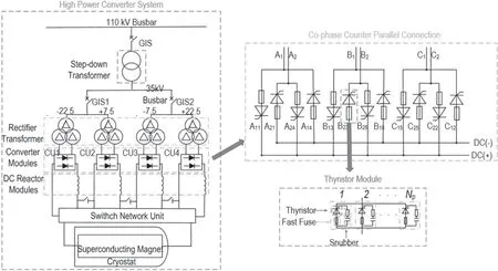
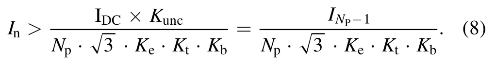
Figure 1.Power supply system topology for CRAFT.
In order to test the superconducting magnet performance of CRAFT,a topology of power supply system is designed (as shown in figure 1).The power supply system is supported by a 110 kV substation with 110 kV busbar.The AC voltage is reduced from 110 kV to 200 V by the step-down and the rectifier transformer.The converter with a DC reactor and switch network unit (SNU) is used to supply the required current and voltage for the superconducting magnet load.The safety,reliability and stable working of converter have a close relationship with the superconductivity load.Depending on the design requirements,the no-load DC output voltage of the converter module is 250 V,and the rated DC output current is 25 kA.The maximum short-circuit current can reach hundreds of kilo-amperes.Compared with conventional highpower converters,both the structure and design parameters have higher technical challenges [9–11].Three-phase bridge rectifier circuit is used for the CRAFT converter because of the wide application and reliable technology.Because the rated voltage converter is low,the co-phase counter parallel connection structure is adopted for reducing the electromagnetic loss,as shown in figure 1.Many thyristors are paralleled in a converter bridge to supply rated current.Each thyristor has an external series fast fuse for short circuit protection and an external paralleled snubber for overvoltage protection.The thyristor,fast fuse and snubber are the key devices of the converter that parameters and types are needed to be determined [12–14].According to the design requirements,the thyristor junction temperature must be lower than 125°C and the thyristor thermal accumulation is lower than the allowable value during the downstream short circuit of DC reactor,the fast fuse must be melted during the bridge short circuit and must not be melt during the downstream short circuit of the DC reactor,the snubber consisting of resistor and capacitor is needed to reduce the commutation over-voltage to be lower than half max repetitive peak forward voltage of thyristor.
3.Thyristor junction temperature and I2t analysis
3.1.Thyristor type analysis and safe threshold determination
Because the thyristor rated voltage (200 V) is very low,the verification parameter is mainly focused on the rated current.High power phase control thyristors mainly include the alloying type and free floating type.The allowable current for the alloying type thyristor is lower than that of the free floating type in the same voltage that will be needed more paralleled thyristors in a converter bridge.Although the minimum voltage (1400 V) of the alloying type thyristor is lower than that of the free floating type (1800 V),the latter one is still preferred due to the cost and volume of the fast fuse and snubber.Meanwhile,the current balance is a serious problem when many thyristors are paralleled to share the rated current together.The converter rated current and short circuit fault current in 100 ms are used to calculate the steady and transient parameters of the thyristor.Combined with steady-state current,surge current and size,the thyristor of 5STP 50Q1800 is selected.
The safe threshold values of voltage and current determination(Kvsfand Kisf)are the first step of thyristor selection,which are calculated as follows:
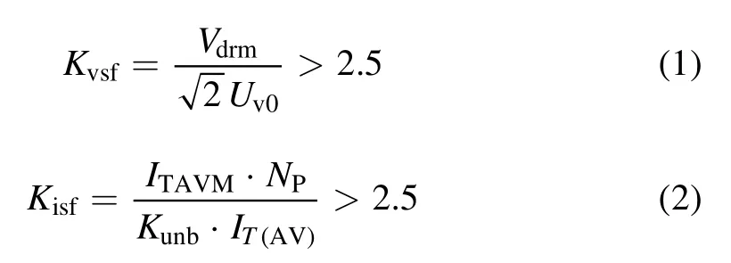
where the Vdrmrepresents the thyristor rated voltage,the Uv0represents the thyristor working voltage.The ITAVMrepresents the thyristor average on-state current,the Nprepresents the parallel number.The Kunbis the current unbalance coefficient of the paralleled thyristor caused by device and current path distance in the converter bridge.The IT(AV)represents the actual current in thyristor at rated state.Based on the above equations with considering the symmetry of the structure,six or more thyristors are selected for parallel analysis of each bridge arm.
3.2.Steady junction temperature analysis
It is necessary to calculate whether the junction temperature exceeds 125°C in steady state operation,so the parallel number can be determined preliminarily.If a thyristor is in a steady state operation,the average current ITAVcan be expressed as equation(3),the power loss PTcan be expressed as equation (4),and the junction temperature Tvjcan beexpressed as equation (5),
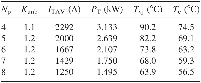
Table 1.Calculated steady parameters of 5STP 50Q1800.
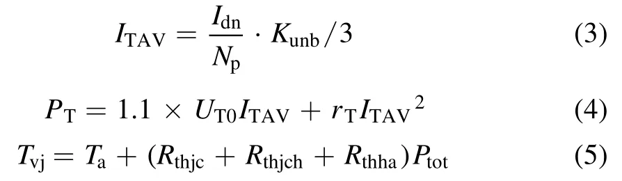
where the Idnis the output current of converter,Npis the parallel number of thyristor,UT0and rtare the steady voltage and resistance of the thyristor.Tais the environmental temperature.Rthjcis the thermal resistance between thyristor junction and thyristor case,Rthchis the thermal resistance between thyristor case and heat sink,Rthhais the thermal resistance between heat sink and air.The steady junction temperature parameters are calculated as given in the table 1.
3.3.Transient junction temperature analysis under short circuit
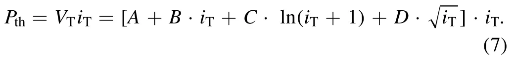
The steady junction temperature is used as the initial temperature during the fault.Thyristor can be equivalent to thermal resistance and heat capacity modules,as shown in figure 2,which are utilized to calculate the transient-state junction temperature.Rthis the thermal resistance of the thyristor,Tvj0is the steady state junction temperature.Pthis the transient power of thyristor.
The fourth-order model in figure 2 can be expressed as equation (6):
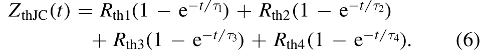
If a thyristor conducts substantial over-current iTin a short time,transient power loss Pthcan be expressed as equation (7):
The fault current waveform is obtained by PSCAD to calculate the thyristor junction temperature curve.The number of parallel connections is determined according to the principle that the thyristor junction temperature is lower than 125°C.Short circuits at the upstream and downstream of the DC reactor are analyzed when the trigger angle of the thyristor is set as 20°.The short circuit time is set at 1.15 s for 100 ms and short circuit waveforms are shown in figure 3.
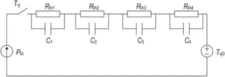
Figure 2.Thyristor thermal resistance and heat capacity model.
It can be seen from figure 3 that the maximum current of upstream short circuit is 366.3 kA at 1.16 s and the upstream short circuit is 150 kA at 1.25 s.The fault junction and thermal effect of the upstream and downstream short circuit of DC reactor are shown in figures 4 and 5.When the upstream of DC reactor is short-circuited with 12 paralleled thyristor in a bridge,the steady case temperature Tvjis 60°C,and the maximum transient junction temperature is 120.2°C.When the downstream of DC reactor is short-circuited with six paralleled thyristor in a bridge,the steady case temperature Tvjis 73.8°C,and the maximum transient junction temperature is 118.0°C.
Six 5STP 50Q1800 thyristors are needed in parallel that meets the requirements of both the voltage and current safety margins which are greater than 2.5.If the transient junction temperature is less than 125°C when the reactor front end is short-circuited,12 thyristors need to be connected in parallel,while only six thyristors need to be connected when the reactor back end is short-circuited.Considering the design cost and space footprint,six thyristors are required for the parallel operation.
4.Fuse parameter determination and overload verification
4.1.Determination of rated parameters
The converter rated voltage on the AC side (200 V) is the rated voltage of fast fuse.The rated current of the fuse can be calculated by equation (8):
where,IDCis the rated output current of converter(30 kA),Keis the cooling coefficient (0.95),Ktis the temperature coefficient (0.9),Kbis the safety margin factor (0.9).When Npis 6,the rated current of the fuse is no less than 4950 A.The fuse 4 URD 233 PLAF 5000 (400 V/5000 A) is selected based on the determination of rated parameters.
4.2.Overvoltage verification
When the fuse arc burns,it will produce an overvoltage that must be lower than the breakdown voltage of the thyristor to prevent the thyristor from being damaged.The relationship between arc voltage and the working voltage of the fuse is illustrated in figure 6.
When the working voltage is 200 V,the arc voltage(925 V) is less than 1800 V,so the thyristor can fully withstand the arc overvoltage of the fuse.
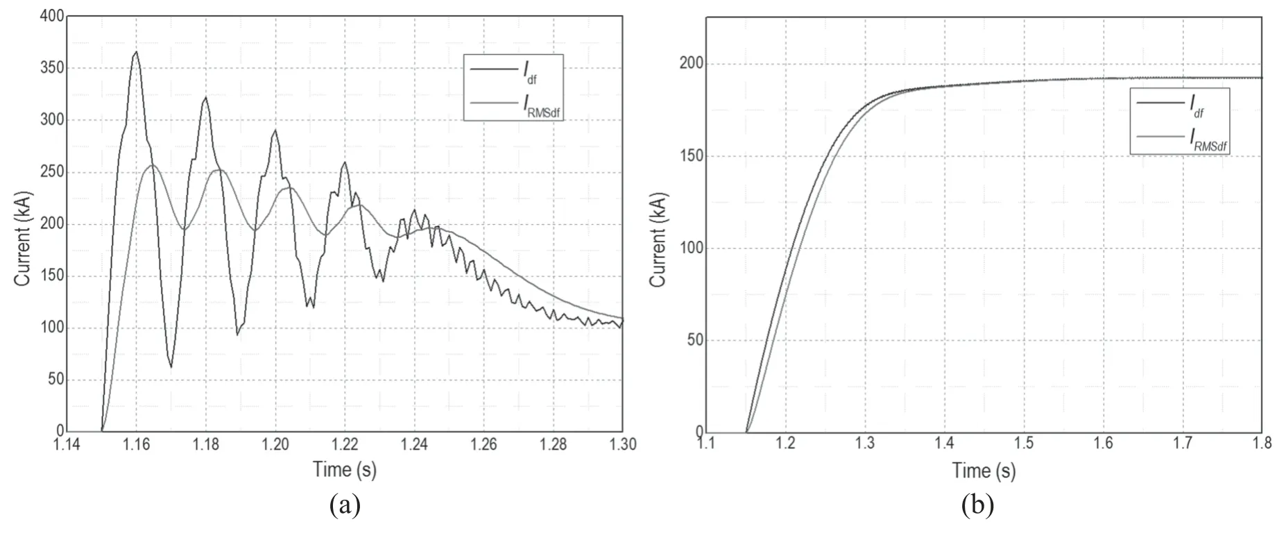
Figure 3.Fault current and effective value of (a) upstream short circuit and (b) downstream short circuit.
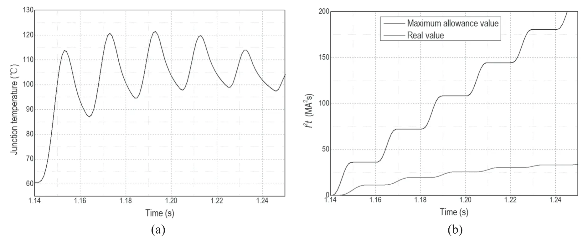
Figure 4.(a) Thyristor junction temperature and (b) I2t of upstream short circuit at DC reactor 2 when Np = 12.
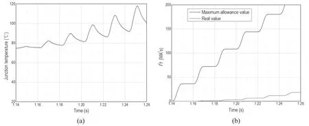
Figure 5.(a) Thyristor junction temperature and (b) I2t of downstream short circuit at DC reactor when Np = 6.
4.3.Overcurrent verification with I2t
When the bridge arm is short-circuited,the fast fuse must be melted to remove the faulty branch.When the bridge arm is short-circuited,if one thyristor is short-circuited,other thyristors will not be switched on by default.At this time,the fault current will flow through the fault branch that is an important criteria for fast fuse analysis.Moreover,the front end of the DC reactor is directly connected with one phase of rectifying transformer,so a short circuit fault is used to simulate the short circuit in the simulation model.The starting time of failure is set at 1.15 s and lasted for 100 ms with a simulation wave shown in figure 7.
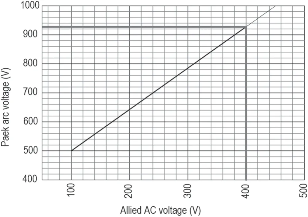
Figure 6.Relationship between applied AC voltage and peak arc voltage of 4 URD 233 PLAF 5000.
The first wave current peak value is 273.7 kA (10 ms),and the effective value is 234.9 kA (30 ms).The current effective value of the bridge fault simulation result and the time current curve of the fuse are compared in the same coordinate system,and the intersection point is the time prearc of the fast fuse,as shown in figure 8.It can be seen from figure 8 that the pre-arc time is 5.015 ms,the effective value of the pre-arc current is 55 390 A,and the pre-arc I2t is 15.38 MA2s.
Figure 9 shows the relationship between the total I2t of the fuse action and the working voltage.Total fuse I2t is the energy used to measure the fuse melting process,which is positively correlated with the actual working voltage.It can be seen from figure 9(a) that when the working voltage is 200 V,the correction factor (K)is 0.58.At the rated voltage,the fuse I2t = 23.1 MA2s.Therefore,when U is 200 V,the total I2tfuse= 0.58 × 23.1 = 13.4 MA2s.Figure 9(b) indicates the relationship between the total operation I2t and the total operation time of the fast fuse,and the parenthesis is the pre-arc time.When the pre-arc time is 5.01 ms,the total action time is about 10 ms.The I2t of thyristor is 20.4 MA2s when t is 10 ms that is larger than the total action time of the fast fuse I2t (13.4 MA2s),and the thyristor can be effectively protected.Thyristor explosion I2t of thyristor is generally two to three times that of the permissible I2t,far more than the total I2t of fuse in the fast melting operation,so it can be ensured that the thyristor will not explode during the operation time.
It can be seen that the calculated results satisfy the verification criterion with a certain margin.At this time,thyristor and fast fuse will not be damaged.Therefore,the fast fuse 4 URD 233 PLAF 5000 is finally selected for the CRAFT converter.
5.Over voltage snubber analysis and design
When the thyristor is turned off,the reverse recovery current between the anode and cathode with the inductive load will cause an overvoltage that may damage the thyristor.Although there is junction capacitance inside the thyristor,an external snubber consisting of resistor and capacitor is needed to reduce the overvoltage to a reasonable level.Both exponential and hyperbolic models can be used to analyze the recovery current,as shown in figure 10.Compared with the exponential model,the hyperbolic model is very complex and the parameters are difficult to determine.Therefore,the exponential model is more applicable to engineering practice.
When t > t1,the reverse recovery current and peak value of rated voltage can be expressed by
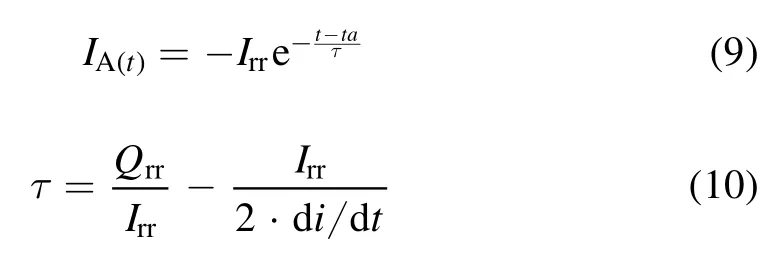
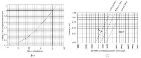
Figure 9.(a)Relationship between total operation I2t and the working voltage.(b)Relationship between the total operation I2t and the total operation time.
Figure 10.Exponential model and hyperbolic model of reverse recovery current.
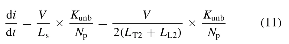
where,V is the peak value of the thyristor rated voltage(278.5 V).Lsis the sum of transformer leakage inductance and AC busbar inductance; LT2is leakage inductance of rectifier transformer (1.55 μH); LL2is AC busbar inductance(2 μH).
The curves of reverse recovery charge (Qrr) and peak value of reverse recovery current (Irr) are obtained from the data sheet shown in figure 11,which is obtained form ABB company online [15].The di/dt is 7.84 A μs-1calculated by equations (9)–(11),the Qrris nearly 7500 μAs and the Irris nearly 220 A obtained from figure 11.When six thyristors are connected in parallel,the total Irris 1320 A,the total Qrris 45 000 μAs.So the reverse recovery current of thyristor can be calculated.
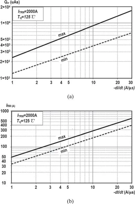
Figure 11.(a) Relationship between the Qrr and di/dt.(b)Relationship between the Irr and di/dt.
We assume that the thyristor in bridge 1 is turned off when bridges 2 and 3 are turned on.In the case of commutation overvoltage,the thyristor reverse recovery current is considered as a controlled current source.The converter with snubber can be equivalent to a simple circuit as shown in figure 12

Figure 12.Equivalent circuit of the converter with snubber during the bridge 1 turning off.
where α is the control angle,μ is the commutation overlap angle.When α + μ = 90°,the commutation overvoltage is the most serious,and this value is adopted for calculation.Rsand Csare the resistor and capacitor of a single thyristor snubber.Reqand Ceqare the equivalent resistor and capacitor of the converter during the phase conversion process.
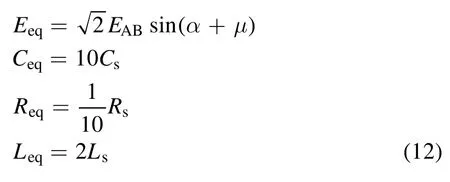
The Ceqis set to10 μF,Reqis set to 2 Ω,the thyristor reverse overvoltage curve is shown in figure 13.At 9.6 μs,the maximum overvoltage is 687.5 V that fully meets the thyristor voltage range (1800 V).Therefore,snubber parameters can comply with the requirements.According to equation (12),the single thyristor snubber resistor R and capacitor C are 20 Ω and 1 μF,respectively.
6.Conclusion
Based on the fault analysis of the upstream and downstream short circuit of the DC reactor,5STP 50Q1800 thyristors are selected for the converter when the parallel number Npis six under the restriction of junction temperature and I2t.The fast fuse 4 URD 233 PLAF 5000 is selected to protect the thyristor and the pre-arc time of the fast fuse is determined,the voltage and current safety margins are verified by analyzing the short circuit of the bridge arm.In order to satisfy the thyristor commutation protection,thyristor reverse recovery current is deduced based on the analysis of multiple parallel snubber equivalent circuit.Each snubber resistor and capacitor are 20 Ω and 1 μF,respectively.This work finished the parameter analysis and type determination of main devices of CRAFT converter,which will be used for the subsequent structure and electromagnetic design.
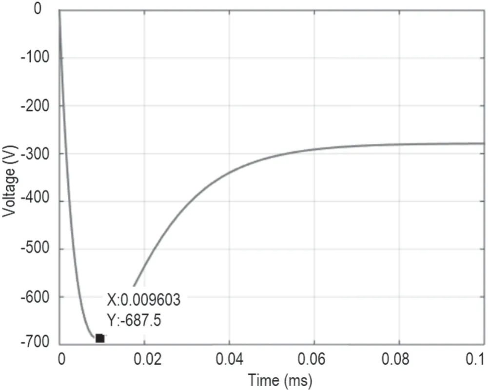
Figure 13.Reverse overvoltage curve of thyristor when Ceq is 10 μF and Req is 2 Ω.
Acknowledgments
This work was supported by the National Key R&D Program of China (No.2017YFE0300504) and Comprehensive Research Facility for Fusion Technology (No.2018-000052-73-01-001228).
ORCID iDs
 Plasma Science and Technology2020年4期
- Plasma Science and Technology的其它文章
- Study on influencing factors of ion current density measurement in corona discharge of HVDC transmission lines
- Trap distribution of polymeric materials and its effect on surface flashover in vacuum
- Improvement of the electrical resistivity of epoxy resin at elevated temperature by adding a positive temperature coefficient BaTiO3-based compound
- Controlling fine particles in flue gas from lead-zinc smelting by plasma technology
- Kinetic simulation of an electronegative plasma with a cut-off distribution and modified Bohm criterion
- Suppression of a spontaneous dust density wave by modulation of ion streaming