
Progressive damage simulation and tensile strength prediction of three-dimensional braided C/C composites considering void defects①
2020-09-05 01:28WEIKunlongSHIHongbinLIJiangTANGMin
固体火箭技术 2020年4期
WEI Kunlong,SHI Hongbin,LI Jiang,TANG Min
(1.College of Astronautics,Northwestern Polytechnical University,Xi'an 710072,China;2.Key Laboratory of Combustion,Thermo-Structure and Internal Flow of SRM,Xi'an Aerospace Solid Propulsion Technology Institute,Xi'an 710025,China)
Abstract:In order to investigate the progressive damage and failure behavior of three-dimensional (3D) braided carbon/carbon (C/C) composites under uniaxial tension,a unit cell model for the 3D braided C/C composite was constructed considering the random void defects in matrix pocket,fiber reinforcement and interface. The failure criterion proposed by Linde was adopted to describe the longitudinal tensile shear failure and transverse tensile failure of fiber bundles. The maximum principal strain criterion was used for the matrix pocket; the cohesive zone model were utilized for modeling interfacial debonding. An exponential damage evolution model related to the element characteristic length,local strain and materials fracture energy was applied. The progressive damage initiation and propagation and failure of the material subjected to uniaxial tension was numerically simulated through ABAQUS UMAT subroutine and periodic boundary conditions,and the axial tensile strength was predicted by the developed model. The results indicate that the axial tensile strength of the 3D braided C/C composite is mainly controlled by the longitudinal tensile strength of axial fiber rods,the strength prediction of numerical model with void defects is much closer to experiment results compared with the prediction of model without void defects,and the influence of void defects on the tensile strength is much greater than that on the tensile modulus.
Key words:3D braided C/C composites;progressive damage model;strength prediction;void defects;finite element method
0 Introduction
The 3D braided C/C composites possess a great advantage of lightweight,high specific strength and stiffness,excellent mechanical performance at high temperature,along with high resistance to delamination and mechanical tailoring capability,therefore,has been recognized as a favorite material for thermo mechanical structure in the fields of aerospace and advanced industry[1-2]. The failure strength is among the mostly concerned performance for material design and engineering application,unlike traditional homogeneous materials,the 3D woven C/C composites inherently has hierarchical level and heterogeneous characteristic,exhibit progressive damage and failure behavior,accompanied by various failure modes[3]. The failure modes of 3D woven composites are special complicated owing to the woven architecture,apart from fiber breakage,matrix cracking and interface debonding,the large amount of manufacturing induced void defects also has a significant effect on the mechanical behavior[4]. It is time consuming and costly high for experimental tests to examine the failure behavior and mechanism of the 3D woven C/C composites,while computational models are flexible and economic,therefore,developing computational models that can predict the damage and failure behavior of the 3D braided C/C composites is very necessary for structure design and material development.
At present,investigation on the failure strength of the 3D braided C/C composites is mainly focused on experimental aspects[5-8],in terms of numerical model,the unit cell model combined with finite element method is commonly employed to carry out the damage and failure analysis of 3D braided composites. Miravete et al[9]investigated the progressive damage of 3D braided composites by using unit cell model and finite element method. Rao M V et al[10]examined the influence of various preform structure on the mechanical properties of 3D braided C/C composites through meso-scale unit cell. Pang B J et al[11]utilized the Murakami damage theory to predict the nonlinear constitutive behavior of 3D four directional braided composites,and simplified meshing process using hybrid elements containing both fiber yarn and matrix. Zako et al[12]established an anisotropic progressive damage model based on Murakami-Ohno damage theory,and two damage factors were utilized to reduce the stiffness of fiber tows,0 for initial undamaged state or 1 for full damaged state. Chang et al[13]performed compressive damage simulation by introducing three factors to degrade the elastic modulus,passion's ratio and shear modulus,three failure modes were taken into account: matrix failure,fiber/matrix shear failure and shear failure of fiber. Xu K et al[14],Zhang F et al[15]used Blackketter stiffness reduction method[16]to simulate the damage of 3D braided composites and 3D Hashin failure criterion was adopted to characterize the different failure modes of fiber yarns. The stiffness reduction scheme is simple for numerical implementation,but the simulation results depend on the choice of the stiffness reduction factors. However,the magnitude of stiffness reduction factors influence the damage process,and numerical results tend to exhibit mesh size dependency since no characteristic length is associated with failure evolution. To alleviate mesh dependency of stiffness reduction method,Bazant and Oh[17]proposed a crack band theory to deal with two dimensional fracture of concrete. Fang G D et al[18]presented a bilinear damage evolution laws based on equivalent displacements to simulate the progressive damage and failure of 3D four directional braided composite. Lu Z X et al[19]and Tan Y Y et al[20]adopted an exponential damage evolution law controlled by the characteristic element length and material fracture toughness to simulate the tensile damage of 3D six-direction composites and 3D needle C/C composites,the numerical results were consistent with experimental results. In order to further take the manufacturing void defects into consideration,Lu Z X et al[21]and Shigang A et al[22]employed zero stiffness element to characterize the void defects,and investigated the effect of void defects on mechanical properties and failure features of plain weave composites and 3D orthogonal woven C/C composites. At present,there are still few literatures on the progressive damage and failure analysis of 3D braided C/C composites,in the manufacturing process,a large amount of randomly distributed void defects are inevitably generated,therefore,the influence of these void defects need to be accounted for in the numerical model.
In present paper,the smallest repeating unit cell for the 3D braided C/C composites was constructed,in which the random void defects in matrix pocket,fiber reinforcement and interface were accounted for. The failure criterion proposed by Linde et al[23]was adopted to characterize the longitudinal and transverse failure of fiber yarns,the maximum strain criterion was utilized for matrix tensile and compressive failure,and an exponential damage evolution model associated with element characteristic length,local strain and materials fracture toughness was presented. The progressive damage and failure of the 3D braided C/C composites subjected to tension was numerically implemented by a developed user-defined material subroutine in Abaqus and the predictive capability of the model is validated by quasi-static tension experiment.
1 Unit cell model considering void defects
1.1 Material
The 3D braided C/C composite examined in this work is presented in Fig.1. The perform is prepared by T300 soft carbon fiber bundles and rigid carbon fiber rods,in which fiber rods are distributed regularly in the axial direction (zdirection),and soft carbon fiber bundles are laid along the fiber rod passages on the plane (x-yplane) vertical to the axial carbon rods. The fiber bundles are arranged periodically around the rigid fiber rods in 0°,60° and -60°angles on thex-yplane. The preform is then densified with a pitch matrix followed by various
cycles of high temperature heat treatment and graphitization to achieve a high density.

(a) Braided style (b) 3D braided C/C compositesFig.1 Braided structure and material sample
The microstructure of the 3D braided C/C composite is observed by scanning electron microscopic photograph (SEM). SEM photographs of the 3D braided C/C composite is shown in Fig.2,it is found that there is a large amount of random void defects inside the matrix pocket,and the shape of voids is approximately ellipsoidal. There are also many micro voids and cracks in the fiber bundles and fiber bundle/matrix interface,which indicates that the fiber bundle and matrix pocket is weakly bonded.

(a) Voids in matrix (b) Voids in fiber bundle (c) InterfaceFig.2 SEM photographs of 3D braided C/C composite
1.2 Unit cell model
The unit cell model for the 3D braided C/C composite is identified according to the periodic woven structure and SEM observations of the material. It is assumed that the cross section of the fiber rod is circular,the cross-section of the radical fiber bundle is rectangular,and the fiber bundles are oriented in a straight line. As displayed in Fig.3,the unit cell is composed of fiber reinforcement,matrix pocket and interface,and the fiber reinforcement includes four fiber rods in the axial and three fiber bundle layers in the radical. The geometric size of the unit cell is 5.54 mm(L)×3.2 mm(W)×3.3 mm(H). The hexagonal and a small number of tetrahedral elements are applied for finite element discretization due to the complex structure,and a total number of 80,900 elements are created. In order to consider fiber bundle/matrix interfacial mechanical behavior,zero thickness cohesive elements are inserted between fiber reinforcement elements and matrix elements by a computer program,and the fiber reinforcement elements and interface elements,the interface elements and matrix elements are connected by same node. It should be noted that the nodes on the opposite faces of the unit cell should be identical in order to impose periodical boundary conditions conveniently.
1.3 Random void defects modeling
The manufacturing defects of C/C composites usually generated during the matrix infiltration and carbonization process,and void defects are the most common type of defects existing in the C/C composites. Considering that the void defects are affected by many mechanism and distributed randomly,therefore,A random function is employed to select some elements as the void elements from the unit cell finite element model. The properties of these void elements are regarded the same as air. DefiningPfvis the void volume fraction of fiber reinforcement,and the method of modeling random void defects is as follows: Firstly,an element is selected from fiber bundles by using the random function. Secondly,the element volume is calculated and put the element into the void elements group. Finally,the elastic properties of the void elements group is set to be zero (1 Pa in the paper). In this way,continue to select other elements randomly until the volume fraction of all selected elements is equal toPfv. Similarly,definingPmvandPivas the void fractions of matrix pocket and interface in the unit cell,respectively. Fig.3 exhibit the construction of unit cell of the 3D braided C/C composites with these three kinds of void defects marked with white color. The averaged volume fraction of void defects in the 3D braided C/C composites is about 5.42%,and the void fractions in matrix pocket,interface and fiber reinforcement are roughly 75%,20% and 5% according to literature[24]. Since the void defects are distributed randomly in the material,the distribution of void may have an effect on the mechanical behavior. In order to consider the effect of voids distribution,three random numerical models with same void volume fraction but different voids distributions are constructed.

(a) Material architecture (b) Unit cell (c) Unit cell finite element model (d) Fiber reinforcement (e) Matrix pocket (f) InterfaceFig.3 Construction of unit cell with void defects
2 Progressive damage model
2.1 Damage initiation criteria for fiber bundle
A fiber bundle is usually composed of thousands of fibers and bonded matrix,and can be regarded as transversely isotropic unidirectional composites. A unidirectional fiber bundle is shown schematically in Fig.4,where fibers are aligned inL-direction and theT-Zplane is assumed to be transversely isotropic. Generally,the failure modes for fiber bundles can be divided into two categories,fiber longitudinal (L-direction) breakage in which failure plane is perpendicular to the fiber direction,inter-tow matrix transverse (TorZdirection) splitting in which failure plane is parallel to fiber direction. In order to indentify the various failure modes occurred in the fiber bundle,failure initiation criteria should be applied. In this paper,the strain-based failure criterion proposed by Linde et al[23]is adopted to describe the quasi-brittle mechanical behavior of fiber bundles in the 3D braided C/C composites.
Fiber longitudinal (L) tensile failure criterion:
(1)
where,ε11f,tis tensile failure strain in the longitudinal (L) direction,ε11f,t=σ11f,t/C11;ε11f,cis compressive failure strain in the longitudinal,ε11f,c=σ11f,c/C11;ε12f,sis longitudinal shear failure strain,ε12f,s=σ12f,s/C44;σ11f,tandσ11f,care tensile and compressive failure strength in the longitudinal (L),respectively;σ12f,sis the shear failure strength in the longitudinal,C11andC44are tensile and shear stiffness in the longitudinal.
Fiber transverse (T,Z) tensile failure criterion:
(2)
(3)
where,ε22f,tandε33f,tare tensile failure strain in the transverse(T,Z) direction,ε22f,s=σ22f,t/C22,ε33f,t=σ33f,t/C33;ε22f,candε33fare compressive failure strain in the transverse,ε22f,c=σ22f,c/C22,ε33f,c=σ33f,c/C33;ε12f,sis longitudinal shear failure strain,ε12f,s=σ12f,s/C44;σ22f,tandσ22f,care tensile and compressive failure strength in the transverse,respectively;σ12f,sis the shear failure strength in the longitudinal,C11andC44were tensile and shear stiffness in the longitudinal.

Fig.4 Local coordinates of a fiber bundle
2.2 Damage initiation criteria for matrix
The tensile and compressive failure are considered for the matrix pocket in the paper,and the maximum principal strain failure criterion is utilized for simplicity. The matrix damage initiates when the matrix maximum principal strain satisfies the following formulas.
fmt=|ε1|≥εmt
(4)
fmc=|ε3|≥εmc
(5)
where,εmtandεmcare tensile and compressive failure strain of matrix,εmt=σmt/C11,ε33f,t=σmc/C11,C11is the tensile stiffness.
2.3 Damage evolution model
The numerical solution exhibits mesh dependency when the damage initiates and material becomes soften,in order to alleviate mesh dependency,the Crack Band Model proposed by Bazant[17]is utilized to relate the finite element size and material fracture toughness. It is assumed in the Bazant’s model that the fracture energy density of one certain fracture mode for material is a constant,then the fracture failure strain will change with finite element size. In present paper,an exponential damage evolution law is adopted to govern the damage propagation.
For the fiber bundles,the damage variables are computed according to the following equations:
(6)
(7)
(8)
where,dL,dTanddZare damage variables in the longitudinal(L),transverse directions(T,Z) for fiber bundle,Lcis the finite element characteristic length,GfandGmare the fracture toughness of fiber and matrix,respectively.
For the matrix pocket,the damage variable are defined and evolved according to the following equation:
(9)
(10)
where,dmtanddmcare damage variables for matrix tensile and compressive failure,εm,tandεm,care tensile and compressive failure strain of matrix,εm,t=σmt/C11,εm,c=σmc/C11,C11is tensile stiffness.
The Murakami-Ohno damage theory is adopted to characterize the damage state and the damage principal directions are assumed to be coincident with the material principal axis. The damage variable is then introduced into the material stiffness matrix to gradually degrade the material stiffness as the damage develops. This damaged matrixCdcan be represented by a stiffness matrix without damageCand a damage variabledi.
(11)
where,bL=1-dL,bT=1-dT,bZ=1-dZ.
Assuming that the damaged elastic matrix isCd,then the stress is updated according to the following equation:
σ=Cd∶ε
(12)
Numerical simulations based on the implicit procedure and the use of material constitutive model considering material stiffness degradation often cause convergence problems. In order to improve the numerical convergence,a viscous regularization scheme is implemented based on the Duvaut-Lions model[25],the damage variables are extracted from below differential equation:
(13)
wheredIis damage variable,dIVis regularized damage variable,ηis viscous parameter (0.001 s in the paper),the above formula can be solved by the differential method in the numerical simulation. If the damage value of the current incremental step isdIt+Δt,the value of the previous incremental step isdIt,the above formula can be expressed as:
(14)
In order to achieve a fast convergence rate for the nonlinear problem associated with damage,the tangent constitutive tensor for fiber yarn and matrix is derived as following formulas:
(15)
(16)
2.4 Damage model for interface
The cohesive zone model (CZM) and traction-separation law are employed to describe the mechanical behavior of interface between fiber bundle and matrix:
tn=Kδn,ts=Kδs,tt=Kδt
(17)
wheretnis the normal traction,tsandttare the shear tractions.δnis the normal separation,δsandδtare the shear separations.Kis the interfacial stiffness,and a quadratic stress criterion is applied for interfacial damage initiation:
(18)
wheretn0andts0are the normal tensile strength and shear strength of interface.
After interfacial damage occurs,a second-order power-law criterion is adopted to govern damage propagation
(19)
Detailed descriptions of the cohesive zone model can be found in the ABAQUS user's manual[26].
3 Constituent material parameters
The 3D braided C/C composites are manufactured by T300 carbon fiber bundles and carbon matrix. The fiber bundles can be regarded as unidirectional fiber-reinforced composites. The mechanical properties of fiber bundles can be calculated using the properties of component materials (fibers and matrix) according to Chamis’ formulas[27]:
E1=VfEf1+(1-Vf)Em
ν12=ν13=Vfνf12+(1-Vf)νm
(20)
whereEf1,Ef2,Gf23andνf12are the longitudinal Young’s modulus,transverse modulus,shear modulus and Poisson’s ratio of fiber,respectively.Em,Gmandνmis the Young’s modulus,shear modulus and Poisson’s ratio of matrix,respectively.Vf,Vmis the volume fraction of fiber and matrix,respectively.
The mechanical properties of T300 carbon fiber and carbon matrix used in present study are summarized in Table 1,it should be noted that the mechanical properties of the carbon matrix and the carbon fibers change after high temperature heat treatments,in particular,strength of the carbon fiber will have a great decline. As it is critical difficult to extract the in-situ mechanical properties of carbon fiber and matrix in the material,therefore,the material properties are determined according to literatures[22,28]and simulation results.

Table 1 Constituent material parameters
4 Periodic boundary conditions
An important aspect of establishing unit cell model for mechanical analysis is the application of the appropriate boundary conditions. In order to keep forces continuity and displacement compatibility of the opposite faces of the unit cell,periodic boundary conditions should be imposed on in the simulation. Xia et al[29]summarized the detailed reality for this particular form of boundary conditions. In present work,the periodic boundary conditions is realized based on multi-point constraint (MPC) equations in Abaqus software.
5 Results and discussions
5.1 Experimental and simulated stress-strain curves
The quasi-static tensile experiments are performed on MTS 858 testing machine at room temperature shown in Fig.5(a). The tensile specimen is designed based on the standards for fiber-reinforced ceramic matrix composite. The geometric diagram of the tensile specimen is depicted in Fig.5(b),and the nominal dimension is 30 mm(length)×11 mm(width)×6.3 mm(thickness). The specimens are griped by aluminum tabs glued on the specimen ends to avoid failure in undesirable locations,and the specimen surface is painted white in order to accurately measure the strain. The experiment is controlled by a loading speed of 0.5 mm/min displacement,and the history of strain is measured by ARAMIS non-contact optical strain measurement system simultaneously.
The experimental and numerical stress-strain curves of the 3D braded C/C composite subjected axial tension are displayed in Fig.6,three defected numerical modes with same void fraction but various distributions are constructed in order to consider the randomness of void defects,and the perfect numerical model is taken for comparison.It is found that all the simulated stress-strain response agrees well with the experimental result in the early stage,and the stress-strain curves tend to be nonlinear as the increase of external strain. Meanwhile,it is clear that the stress-strain curves of the defected numerical model agree much better with experimental curve than that of the perfect numerical model without void defects. The predicted tensile elastic modulus for the three defected numerical models are almost the same according to the initial linear portion of stress-strain curves,and the average tensile modulus for the defected model and intact model is 54.3 GPa and 54.9 GPa,respectively,while the experimental tensile modulus of the 3D braided C/C composites is 52.3 GPa. In the viewpoint of modulus,the deviations between numerical and experimental elastic modulus are 3.8% for defected model and 4.9% for intact model,the difference between two numerical models is only 1.1%,therefore,void defects have relatively limited impact on the tensile elastic modulus of the 3D braided C/C composite.

(a) Test machine (b) Geometric dimensions of tensile specimenFig.5 Experiment and specimen
In the view of strength,the predicted tensile strengths for three defected numerical models with same void fraction but various distributions are 102.73 MPa,101.29 MPa and 99.3 MPa,respectively,which indicate that the random distribution has an effect on the simulated tensile strength. The averaged value of the three defected models is 101.11 MPa,which is then taken as the predicted tensile strength of the 3D braided C/C composites. Meanwhile,the predicted tensile strength for the perfect numerical model is 132.15 MPa,and the experimental tensile strength is 109.22 MPa. The deviations between the predicted and experimental tensile strength are 7.42% for the defected numerical model and 20.99% for the intact numerical model. Compared with numerical model without considering void defects,the predicted tensile strength of numerical model considering void defects decline 23.49%,which indicates that manufacturing void defects have a great influence on the tensile strength of the 3D braided C/C composite.

Fig.6 Tensile stress-strain curves of the 3D braided C/C composite
5.2 Failure mechanism and damage evolution
The damage evolution of matrix pocket,interface and fiber reinforcement in the perfect and defected numerical models are given in Fig.7~Fig.9,respectively,in which SDV1 denotes damage variable for matrix pocket and fiber,and SDEG denotes damage variable for interface. For the numerical model with void defects,damage states at three different points ‘i’,‘j’ and ‘k’ on the stress-strain curves in Fig.6 are examined. For the numerical model without void defects,damage states at three different points ‘o’,‘p’ and ‘q’ in Fig.6 are extracted. It is found that the matrix pocket and interfaces between radial fiber rods and matrix pocket are firstly damaged under axial tension,the stress-strain curves exhibited nonlinear behavior as the damaged region expanded,which indicate that the nonlinearity of stress-strain curve under axial tension is mainly caused by matrix and interface damage. When the stress-strain curves reach the peak point,fiber longitudinal damage occur in the axial fiber rods,which implies that the axial tensile strength of the 3D braided C/C composite is mainly controlled by axial fiber rods. Meanwhile,it is found that damaged regions in the numerical model containing void defects is more decentralized than the numerical model without void defects.

(a) Model with voids (b) Model without voidsFig.7 Damage evolution in matrix pocket

(a) Model with voids (b) Model without voidsFig.8 Damage evolution in interface
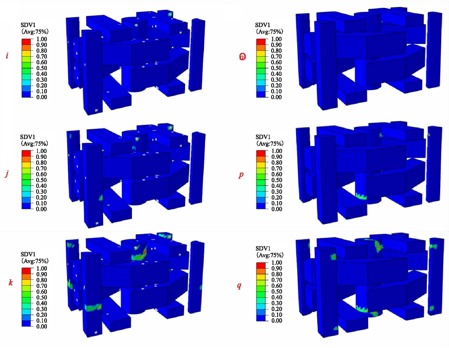
(a) Model with voids (b) Model without voidsFig.9 Damage evolution in fiber reinforcement
The failure mode and fracture morphology of the 3D braided C/C composite specimen under axial tension are presented in Fig.10 and Fig.11,respectively. It can be seen that axial fiber rods are pulled out from the matrix pocket,which indicate that the interfacial debonding between axial fiber rod and matrix pocket happened under axial tensile loading. All the axial fiber rods are broken in the longitudinal direction,which is similar to the failure patterns obtained from numerical simulation. Therefore,it can be concluded that the axial tensile strength of the 3D braided C/C composites is mainly controlled by the longitudinal tensile strength of axial fiber rods.

Fig.10 Failure mode of 3D braided C/C composites under axial tension

Fig.11 The fracture morphology of the 3D braided C/C composites under axial tension
6 Conclusions
(1) A progressive damage model is developed for the 3D braided C/C composites considering randomly distributed void defects in matrix,fiber reinforcement and interface. The progressive damage and failure behavior of the material subjected to tension is predicted through user-defined material subroutine in ABAQUS. The predictions basically agree with experimental results,including the initial elastic modulus,nonlinear stress strain response,and tensile strength,demonstrating the validity of the developed numerical model.
(2) The main failure mode of the 3D braided C/C composites subjected to tension in axial direction is the longitudinal tensile breakage of fiber rods. The void defects have a decreasing effect on the predicted tensile strength,prediction of numerical model considering void defects is much closer to experimental result compared with model without void defects,and the influence of void defects on the tensile strength is much greater than on the tensile modulus.
