
On the heating mechanism of electron cyclotron resonance thruster immerged in a non-uniform magnetic field
2020-09-14 01:13XiaogangYUAN袁小刚LeiCHANG苌磊XinYANG杨鑫HaishanZHOU周海山andGuangnanLUO罗广南
Plasma Science and Technology 2020年9期
关键词:海山
Xiaogang YUAN (袁小刚),Lei CHANG (苌磊),Xin YANG (杨鑫),Haishan ZHOU (周海山) and Guangnan LUO (罗广南)
1 Institute of Plasma Physics,Chinese Academy of Sciences,Hefei 230031,People’s Republic of China
2 Science Island Brand of Graduate,University of Science and Technology of China,Hefei 230031,People’s Republic of China
Abstract
Keywords:electron cyclotron resonance,upper hybrid resonance,non-uniform magnetic field,electric thruster
1.Introduction
There is a rapidly growing number of studies on electrodeless plama source for electric thruster[1-4]which have a long life span due to the absence of electrode erosion problem.Plasma production and heating in these thrusters are achieved by alternate current antennas,radiating mainly in the microwave or radio frequency ranges.Electron cyclotron resonance thruster (ECRT) is one of them.Due to the high specific impulse and durability,it becomes a promising thruster for space applications including orbital transfer,attitude control and deep space travel,etc [5].A typical ECRT consists of four parts:microwave source,magnet,resonance cavity and acceleration grid[6,7],as depicted in figure 1.The magnet is critical to generate plasma and confine the formed plasma thereafter.Particularly,the plasma can be ignited by microwave at the frequency of 2.45 GHz (or 4.2 GHz) with a magnetic field strength of 0.0875 T (or 0.15 T) [8,9],according to the electron cyclotron resonance.Permanent magnet and solenoid coil are commonly applied for generating a magnetic field.However,the former one suffers from demagnetization during long-time operation,especially when the temperature is high.As a result,the usage of solenoid coil becomes a tendency,especially when steady state operation is highly required for certain space missions.However,the requirement of electric power to run the solenoid coil increases the total power consumption of the thruster system.Since the coil current is proportional to magnetic field strength,it is thereby highly desirable to run ECRT at low field to save power.Theoretical analysis suggests that ECRT can run at low magnetic field by using upper hybrid resonance[10].But to the author’s knowledge,there is few experimental verification of it.Meanwhile,the study of coupling and transition between electron cyclotron resonance and upper hybrid resonance is also missing.Moreover,the non-uniformity of confining magnetic field was rarely explored which is critical for optimizing the ECRT performance.

Figure 1.Schematic of typical ECRT.
The aim of the present work is to investigate the heating mechanism of ECRT in a non-uniform field and explore the minimum field strength for efficient operation.It will be shown that high field (0.0875 T) is only required for the ignition of the plasma and the formed plasma can indeed sustain for magnetic field decreased till 0.0170 T.Moreover,the ignition of the plasma and sustained plasma at low-field are driven by electron cyclotron resonance and upper hybrid resonance,respectively.The transition between two modes is also revealed experimentally.The paper is organized as follows:section 2 describes the experimental setup and parameters,and section 3 shows the results and discussions,followed by conclusions in section 4.
2.Experimental setup and parameters
Experiments were carried out on an electron cyclotron resonance plasma source at the Institute of Plasma Physics,Chinese Academy of Sciences (ASIPP).It is a component of the linear plasma device named PREFACE (Permeation and Retention Evaluation FACility for fusion Experiments),which was built to evaluate the permeation and retention behavior of fusion material under plasma exposure [11-13].Figure 2 shows a schematic of the PREFACE,together with typical photos of plasma discharge.It has three cylindrical coaxial vacuum chambers,that is,the plasma discharge chamber,diffusion chamber and sample processing chamber.The total axial height is 0.847 m.The magnetic field of strength 0-0.2 T is provided by four solenoid coils with independent control.The resonance cavity and solenoid coils are water cooled by a system of copper pipes.Tantalum limiter with a diameter of 0.04 m is used to confine the plasma column.The vacuum is maintained jointly by a turbo-molecular pump and mechanical pump,giving base pressure of 10−6Pa.The working gas is deuterium,which is injected into the vacuum chamber from the top side and the gas flow is controlled by a pin valve.In this study,the operating pressure was set to 0.6 Pa.A solid-state microwave source with 2.45 GHz frequency and a power range of 0-2 kW was applied to generate plasma.The plasma jet injected into the diffusion chamber due to diffusion.It has a similar structure as a traditional ECRT expected for that the acceleration grid is not present.Therefore,the electron cyclotron resonance plasma source of PREFACE can be used to study the basic heating physics of ECRT.Since there are four independently controlled solenoid coils,the spatial configuration of the external magnetic field is highly flexible,which also denotes the specialty of present work.In order to measure the radial profiles of electron density and temperature,a Langmuir probe (Hiden ESPION) with a tip in diameter of 0.000 15 m and 0.01 m length is inserted radially into the chamber.The radial resolution is up to 0.0025 m.The axial location of the probe is 0.3 m from the top window,as shown in figure 2,and z=0.547 m referring to figures 3 and 7,8 in the next sections.The error bar of each data was from averaging 5 cycles of measurements.
To study the heating mechanism of ECRT,especially the effect of magnetic field strength on plasma generation,six scenarios of coil current are considered (table 1).The typical axial profiles of the magnetic field,calculated from the coil current of Scenarios #1,#2,#3 and #6 by COMSOL Multiphysics are shown in figure 3.These scenarios share the same non-uniformity expect that the magnitudes are different.It is worth noting that the non-uniformity is both radial and axial.The framed ‘Resonance cavity’ corresponds to the discharge chamber of PREFACE shown in figure 2.The nonuniform field profiles are constructed to form a magnetic mirror in the resonance cavity region for particle confinement.Meanwhile,the magnetic field formed a shape of magnetic‘Laval nozzle’ near the interface of discharge and diffusion chambers for acceleration purpose.Recalling our motivation to explore the minimum field for efficient ECRT operation,we start from high field (Scenario #6) condition that the plasma ignition just occurs,and then gradually reduce the field till the minimum field (Scenario #1) that can be produced by the solenoid coils.In our experiments,the plasma can sustain with field strength decreased to the case of Scenario#1.However,in the opposite direction(from Scenarios#1 to Scenarios #5),we could not ignite the plasma with input power in the range of 0-600 W until the field strength increased to Scenario #6.It will be shown later that the first harmonic of electron cyclotron resonance surface,which is associated with a high magnetic field,is essential for ignition,and upper hybrid resonance could sustain the plasma after ignition at a low magnetic field.
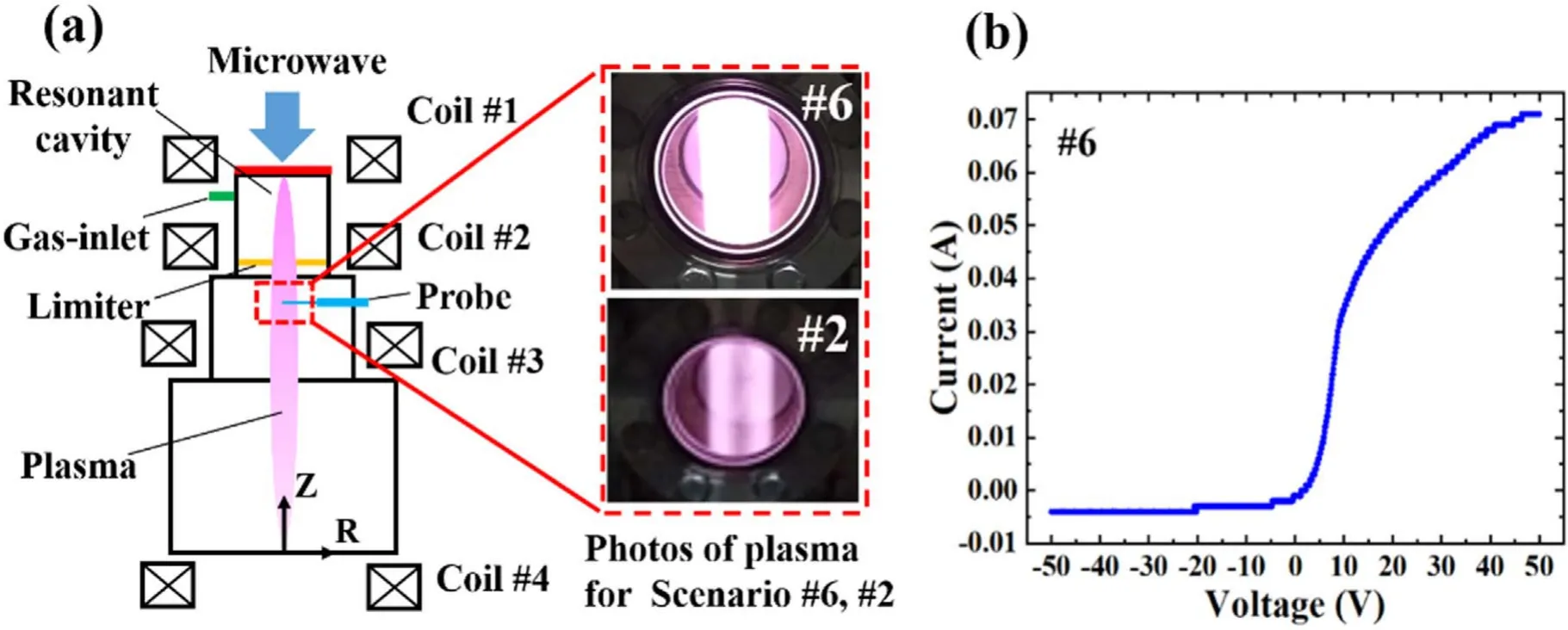
Figure 2.Schematic of PREFACE(Permeation and Retention Evaluation FACility for fusion Experiments)in ASIPP(a).From top to bottom are the plasma chamber,diffusion chamber,and sample processing chamber in sequence.A typical V-I curve from Langmuir probe measurement for Scenario #6 (b).
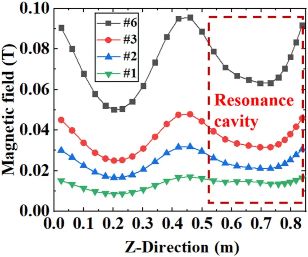
Figure 3.Axial profiles of magnetic field calculated by COMSOL Multiphysics for Scenarios #1,#2,#3 and #6.The dashed frame labels the resonance cavity in figure 2.
3.Results and discussions
3.1.Electron density and temperature
The electron density and temperature for the six scenarios are given in figure 4.They are measured by Langmuir probe at r=0 m and z=0.547 m for the microwave of power 600 W(r,z start position is shown in figure 2).We can see that,when the magnetic field strength decreased,the electron density increases first and then decreases sharply,maximizing at 3.21×10¹⁷m−3for Scenario #3,while the electron temperature decreases first and then increases significantly,minimizing at 1.58 eV for Scenario#3.These two opposite trends imply that there may be a competition of power deposition for electron density and temperature.Moreover,the special point of Scenario #3 perhaps labels the transition and coupling between electron cyclotron resonance mode at high field and upper hybrid resonance mode at low field.These two modes can be confirmed and differed in the experiment through the radial profile of plasma density and the magnetic field strength.That is because electron cyclotron resonance is dominant under high field strength,whereas upper hybrid resonance is dominant under low field strength.Moreover,due to the strong edge heating effect of upper hybrid resonance,it has a ‘hollow’ density profile in radius and the plasma is brighter in the edge (inserted photo of figure 2(a)).While the ECR mode has a ‘peak’ density profile and the plasma has a bright core.This phenomenon will be discussed in the following part.
Figure 5 shows the dependences of electron density and temperature on input power for Scenarios #6,measured at r=0 m and z=0.547 m.It can be seen that the electron density increases gradually before a sharp jump at 550 W,while the electron temperature jumps at 150 W before saturating around 2.75 eV.This difference in power response may be attributed to the different thresholds of power deposition required for cyclotron and ionization.Namely,the electron cyclotron motion is more sensitive to microwave and thus can respond quickly to the increased power.Whereas the ionization procedure depends on power deposition which needs a certain level to happen,leading to the ‘delayed’ response to increased power.
We think that the ‘delayed’ response is mainly due to a power-threshold problem.Although this preliminary explanation may be reasonable,detailed exploration is definitely required for further research.
The radial profiles of electron density and temperature for Scenarios #6,#2 and #1 are given in figure 6.We can see that:(1) for Scenario #6 the electron density has a peak on axis and decreases towards the radial edge,while the electron temperature profile is uniform inside most of column regions,(2)for Scenario#2 the radial density profile becomes hollow.It is consistent with the photo shown in figure 2.The plasma is brighter near edge than that on axis,and the temperature gradient becomes more linear in radius,(3) for Scenario #1the electron density becomes roughly uniform across the column except for a significant drop near the edge,while the electron temperature has a radial gradient especially in the core and near edge.Recalling the axial profiles of the magnetic field shown in figure 3,we suppose the underlying physics is mainly correlated with the strength of the confining magnetic field.The electron cyclotron resonance mode depends sensitively on field strength and dominates the heating procedure at high field.The upper hybrid resonance mode generates plasma on the edge.The transition from electron cyclotron resonance mode to the upper hybrid resonance mode leads to a hollow (at least uniform) density profile at low field.Looking backward in figure 4,this
transition or coupling is strongest at Scenario #3 so that the highest electron density is obtained.Please note that this evolution of electron density and temperature with decreased field strength,which shows the transition and coupling from electron cyclotron resonance mode to upper hybrid resonance mode,was not revealed before.The hollow density profile in radius has been also observed in previous studies [14,15],which proves the credibility of present work,and the direct loss of trapped electrons was suggested to be the reason.
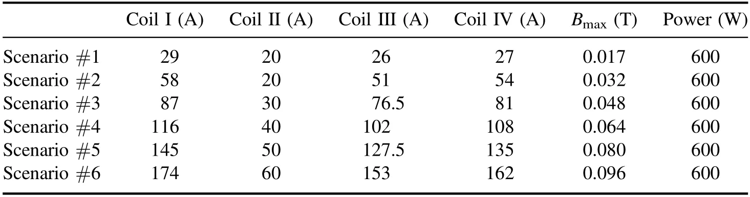
Table 1.Scenarios of coil current and peak magnetic field strength.
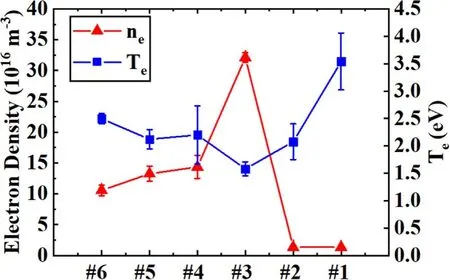
Figure 4.Electron density and temperature for different scenarios,measured at r=0 m and z=0.547 m,for microwave of power 600 W.
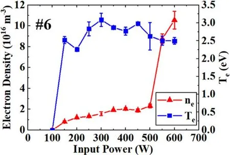
Figure 5.Electron density and temperature for Scenarios #6 as a function of the microwave input power.

Figure 6.Radial profiles of electron density and temperature for Scenario #6 (a),#2 (b) and #1 (c),measured at z=0.547 m.
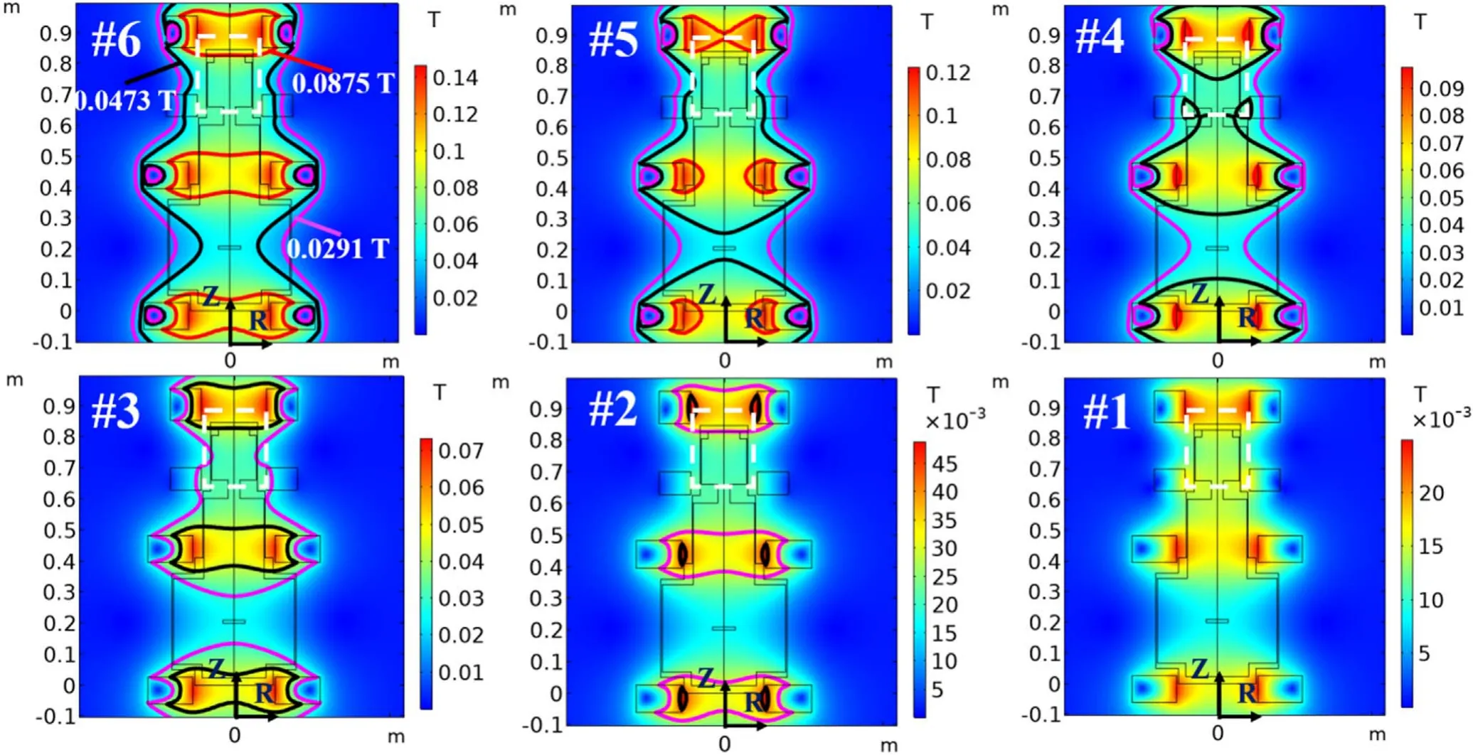
Figure 7.Contour plots of magnetic field in PREFACE for the six scenarios in table 1,showing the surfaces of electron cyclotron resonance(red:first harmonic for 0.0875 T,black:second harmonic for 0.0473 T,pink:third harmonic for 0.0291 T).The dashed white frame labels the edges of the resonant cavity.
3.2.Electron cyclotron resonance surface
In order to explain the phenomena observed above,we studied the electron-microwave interaction,especially the electron cyclotron resonance surface which was believed to be the strongest interaction.Once electrons gain enough energy from microwave resonance,they can ionize neutral gas through collisions to produce plasma.The regulatory choice of 2.45 GHz for microwave results in magnetic field strength of 0.0875 T,according to the electron cyclotron frequency [16]
here,B is the applied magnetic field,meis the electron mass andωceis the cyclotron frequency of electron.In experiments,the magnetic field with a strength higher than 0.0875 T is generally employed to account for the field non-uniformity in space.Figure 7 shows the contour plots of the magnetic field for the six scenarios listed in table 1,from which we can see the location of the electron cyclotron resonance surface relative to the source chamber.Scenario#6 has three electron cyclotron resonance surfaces:first harmonic (red),second harmonic(black)and third harmonic(pink).But only the first harmonic resonance surface(the red part shown in figure 7 for Scenario #6) resides in the resonant cavity region.As the field strength decreased,i.e.from Scenario #6 to Scenario#1,the first harmonic surface moves outside of the resonant cavity,while the second and third harmonic surfaces move across it.Given that only Scenario#6 yields plasma ignition,it is reasonable to make the conclusion that the existence of the first harmonic surface in the resonant cavity is essential for plasma ignition.For Scenario #4,the second harmonic surface exists in the cavity but could not ignite the plasma in our experiments.Therefore,the result negates a previous statement which was claiming that plasma could be ignited without the first harmonic surface as long as the second harmonic surface exists [17].However,once the plasma has been ignited for Scenario#6,it can continuously run with the field strength decreased from Scenario #5 to Scenario #1.This mystery will be further investigated in the next section.
3.3.Upper hybrid resonance
Since at low magnetic field the continuous plasma after ignition cannot be supported by electron cyclotron resonance which does not exist inside the resonant cavity,we have to consider other possible candidates.Referring to the previous study [10],we consider the upper hybrid resonance.It is a normal mode of plasma heating [18-21],and the resonance frequency is given by
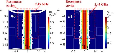
Figure 8.Contour plots of frequency for Scenario#6 and Scenario#1 with plasma sustained in the source chamber of PREFACE.The solid white line labels resonance frequency of 2.45 GHz and a dashed red frame encloses the resonant cavity.
here,ωuhis the angular frequency of upper hybrid resonance,ωpeis the angular frequency of plasma,andωceis the angular frequency of electron cyclotron motion.Please note that the frequency given by equation(2)is a local value.To calculate the two-dimensional distribution of upper hybrid resonance in the plasma discharge chamber,we make use of the radial profiles of electron density and temperature shown in figure 6 and assume that they are roughly uniform along the axial direction.Figure 8 shows the contour plots of frequency inside the resonant cavity for Scenario #6 and Scenario #1.Both of electron cyclotron resonance and upper hybrid resonance are contributed to the plasma heating in Scenario #6.However,there is no electron cyclotron resonance but only upper hybrid resonance exists in Scenario#1,referring to the last plot of figure 7.Recalling figure 5,we can conclude that the plasma is ignited by the first harmonic surface of electron cyclotron resonance,and then sustained mainly by the upper hybrid resonance which generates plasma near column edge(see the hollow plasma photo in figure 2).This is consistent with a previous study which claimed that with a decreasing magnetic field the upper hybrid resonance gradually dominates the plasma heating of ECRT[22].Hence,there are two different channels of plasma heating:electron cyclotron resonance at high field and upper hybrid resonance mainly at low field.Detailed evolution of frequency contour from Scenario #6 to Scenario #1 also shows a transition from electron cyclotron resonance to upper hybrid resonance.
4.Conclusion
The present work is devoted to studying the mechanism of plasma ignition and continuous running for ECRT,and exploring the effects of a non-uniformity and field strength of confining magnetic field for economic operation.Six scenarios of the magnetic field are considered.It is found that the first harmonic surface of electron cyclotron resonance is essential for plasma ignition at high field,and the upper hybrid resonance is responsible for plasma sustaining after ignition at low field.With the field strength decreased,the variation of electron density behaves oppositely with that of electron temperature,implying a possible competition of power deposition between them.Moreover,their dependences on the input power of microwave also show a ‘delayed’phase,possibly due to the different thresholds of power requirement.The radial profiles of electron density and temperature for different scenarios are also presented.For decreased field strength,the density profile changes from linear to hollow and flat,possibly due to weakened magnetic constraint,while the temperature profile turns from flat to linear.Again,the dependences of density and temperature on field strength are opposite,even in terms of their radial profiles.These findings could improve our understanding of the plasma discharge using electron cyclotron resonance,and help the design of efficient ECRT by applying a non-uniform and low magnetic field.
Acknowledgments
The authors would like to thank Professor Yemin Hu for fruitful discussions on the mechanism of electron cyclotron resonance and upper hybrid resonance,and Professor Bo Li for engineering assistance.This work is supported by various funding sources:Chinese Academy of Sciences ‘100 Talent’Program (B),Pre-research of Key Laboratory Fund for Equipment (No.61422070306),Shanghai Engineering Research Center of Space Engine (No.17DZ2280800),National Postdoctoral Program for Innovative Talents (No.BX201700248),and China Postdoctoral Science Foundation(No.2017M622035).
猜你喜欢
风流一代·经典文摘(2019年7期)2019-07-18
37°女人(2019年4期)2019-04-20
地理教育(2018年10期)2018-12-08
百科探秘·海底世界(2018年1期)2018-08-04
百科探秘·海底世界(2018年3期)2018-08-03
故事会(2018年12期)2018-06-23
科学导报(2018年18期)2018-05-14
作品(2016年10期)2016-12-06
大江南北(2016年3期)2016-11-22
微型小说选刊(2014年10期)2014-11-14
 Plasma Science and Technology2020年9期
- Plasma Science and Technology的其它文章
- Impact of exterior electron emission on the self-sustaining margin of hollow cathode discharge
- Research on the neutralization control of the RF ion micropropulsion system for the‘Taiji-1’ satellite mission
- Study on the influence of the discharge voltage on the ignition process of Hall thrusters
- The plume diagnostics of 30 cm ion thruster with an advanced plasma diagnostics system
- Performance of a 4 cm iodine-fueled radio frequency ion thruster
- Experimental investigation on the plasma morphology of ablative pulsed plasma thruster with tongue-shaped and flared electrodes